2007 ISUZU KB P190 EGR
[x] Cancel search: EGRPage 1468 of 6020
6A-108 ENGINE MECHANICAL (4JK1/4JJ1)
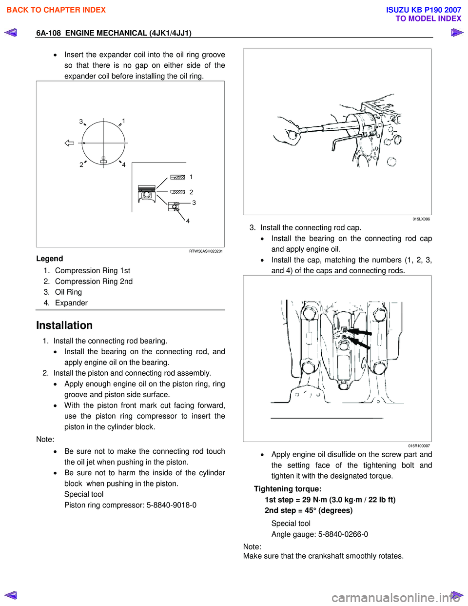
• Insert the expander coil into the oil ring groove
so that there is no gap on either side of the
expander coil before installing the oil ring.
RTW 56ASH023201
Legend
1. Compression Ring 1st
2. Compression Ring 2nd
3. Oil Ring
4. Expander
Installation
1. Install the connecting rod bearing.
• Install the bearing on the connecting rod, and
apply engine oil on the bearing.
2. Install the piston and connecting rod assembly. • Apply enough engine oil on the piston ring, ring
groove and piston side surface.
• W ith the piston front mark cut facing forward,
use the piston ring compressor to insert the
piston in the cylinder block.
Note: • Be sure not to make the connecting rod touch
the oil jet when pushing in the piston.
• Be sure not to harm the inside of the cylinde
r
block when pushing in the piston.
Special tool
Piston ring compressor: 5-8840-9018-0
015LX096
3. Install the connecting rod cap.
• Install the bearing on the connecting rod cap
and apply engine oil.
• Install the cap, matching the numbers (1, 2, 3,
and 4) of the caps and connecting rods.
015R100007
• Apply engine oil disulfide on the screw part and
the setting face of the tightening bolt and
tighten it with the designated torque.
Tightening torque: 1st step = 29 N ⋅
⋅⋅
⋅
m (3.0 kg ⋅
⋅⋅
⋅
m / 22 lb ft)
2nd step = 45° (degrees)
Special tool
Angle gauge: 5-8840-0266-0
Note:
Make sure that the crankshaft smoothly rotates.
BACK TO CHAPTER INDEX
TO MODEL INDEX
ISUZU KB P190 2007
Page 1474 of 6020
6A-114 ENGINE MECHANICAL (4JK1/4JJ1)
015RY00010
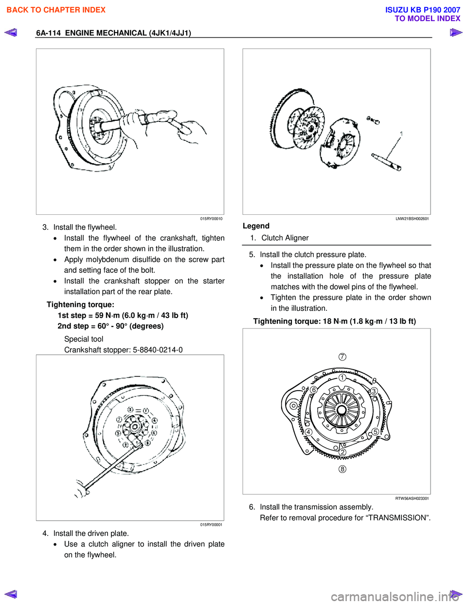
3. Install the flywheel.
• Install the flywheel of the crankshaft, tighten
them in the order shown in the illustration.
•
Apply molybdenum disulfide on the screw part
and setting face of the bolt.
• Install the crankshaft stopper on the starte
r
installation part of the rear plate.
Tightening torque: 1st step = 59 N ⋅
⋅⋅
⋅
m (6.0 kg ⋅
⋅⋅
⋅
m / 43 lb ft)
2nd step = 60° - 90° (degrees)
Special tool
Crankshaft stopper: 5-8840-0214-0
015RY00001
4. Install the driven plate.
• Use a clutch aligner to install the driven plate
on the flywheel.
LNW 21BSH002601
Legend
1. Clutch Aligner
5. Install the clutch pressure plate.
• Install the pressure plate on the flywheel so that
the installation hole of the pressure plate
matches with the dowel pins of the flywheel.
• Tighten the pressure plate in the order shown
in the illustration.
Tightening torque: 18 N ⋅
⋅⋅
⋅
m (1.8 kg ⋅
⋅⋅
⋅
m / 13 lb ft)
RTW 56ASH023301
6. Install the transmission assembly.
Refer to removal procedure for “TRANSMISSION”.
BACK TO CHAPTER INDEX
TO MODEL INDEX
ISUZU KB P190 2007
Page 1488 of 6020
6A-128 ENGINE MECHANICAL (4JK1/4JJ1)
Reassembly
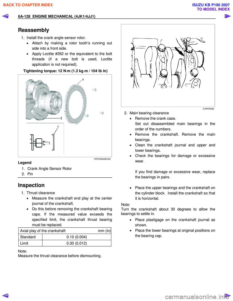
1. Install the crank angle sensor rotor.
• Attach by making a rotor tooth’s running out
side into a front side.
•
Apply Loctite #262 or the equivalent to the bolt
threads (if a new bolt is used, Loctite
application is not required).
Tightening torque: 12 N ⋅
⋅⋅
⋅
m (1.2 kg ⋅
⋅⋅
⋅
m / 104 lb in)
RTW 76ASH001601
Legend
1. Crank Angle Sensor Rotor
2. Pin
Inspection
1. Thrust clearance
• Measure the crankshaft end play at the cente
r
journal of the crankshaft.
• Do this before removing the crankshaft bearing
caps. If the measured value exceeds the
specified limit, the crankshaft thrust bearing
must be replaced.
Axial play of the crankshaft mm (in)
Standard 0.10 (0.004)
Limit 0.30 (0.012)
Note:
Measure the thrust clearance before dismounting.
015RY00002
2. Main bearing clearance
• Remove the crank case.
Set out disassembled main bearings in the order of the numbers.
• Remove the crankshaft. Remove the main
bearings.
• Clean the crankshaft journal and upper and
lower bearings.
• Check the bearings for damage or excessive
wear.
If you find damage or excessive wear, replace the bearings in pairs.
• Place the upper bearings and the crankshaft on
the cylinder block. Install the crankshaft so that
it is horizontal.
Note:
Turn the crankshaft about 30 degrees to allow the
bearings to settle in.
• Place plastigage on the crankshaft journal as
shown.
• Place the lower bearings at original positions on
the bearing cap.
BACK TO CHAPTER INDEX
TO MODEL INDEX
ISUZU KB P190 2007
Page 1543 of 6020
6C-2 FUEL SYSTEM (4JK1/4JJ1)
Fuel System
Service Precautions
Parts of the fuel system such as the internal part of the
fuel injector, and holes and clearances that form
passages for fuel are finished to a very high degree o
f
accuracy. They are therefore highly sensitive to foreign
matter and the entry of foreign matter could cause
damage to the fuel passage. Therefore, effective
measures should be taken to prevent the entry o
f
foreign matter.
If a water removal agent is used in the fuel then it will
absorb moisture in the light oil and may cause rust.
Therefore, do not use a water removal agent in the fuel
tank.
W hen servicing the fuel system, every precaution must
be taken to prevent the entry of foreign material into the
system.
• Before beginning the service procedure, wash the
fuel line and the surrounding area.
• Perform the service procedures with clean hands.
Do not wear work gloves.
• Immediately after removing the fuel hose and/o
r
fuel pipe, carefully tape vinyl bags over the
exposed ends of the hose or pipe.
• If parts are to be replaced (fuel hose, fuel pipe,
etc.) do not open the new part packaging until
installation.
Discard gaskets and O-rings and replace them with ne
w
ones.
Work procedure
•
The fuel opening must be quickly sealed when
removing the fuel pipe, injection pipe, fuel injector,
fuel supply pump, and fuel rail.
• The eyebolts and gasket must be stored in a clean
parts box with a lid to prevent adhesion of foreign
matter.
• Fuel leakage could cause fires. Therefore, afte
r
finishing the work, wipe off the fuel that has leaked
out and make sure there is no fuel leakage afte
r
starting the engine.
BACK TO CHAPTER INDEX
TO MODEL INDEX
ISUZU KB P190 2007
Page 1562 of 6020
FUEL SYSTEM (4JK1/4JJ1) 6C-21
Fuel Rail Assembly
Components
RTW 76CLF000301
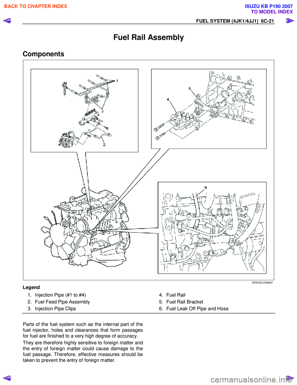
Legend
1. Injection Pipe (#1 to #4)
2. Fuel Feed Pipe Assembly
3. Injection Pipe Clips
4. Fuel Rail
5. Fuel Rail Bracket
6. Fuel Leak Off Pipe and Hose
Parts of the fuel system such as the internal part of the
fuel injector, holes and clearances that form passages
for fuel are finished to a very high degree of accuracy.
They are therefore highly sensitive to foreign matter and
the entry of foreign matter could cause damage to the
fuel passage. Therefore, effective measures should be
taken to prevent the entry of foreign matter.
BACK TO CHAPTER INDEX
TO MODEL INDEX
ISUZU KB P190 2007
Page 1608 of 6020
6D-20 ENGINE ELECTRICAL (4JK1/4JJ1)
Inspection and Repair
Make the necessary adjustments, repairs, and part
replacement if excessive wear or damage is discovered
during inspection.
Armature
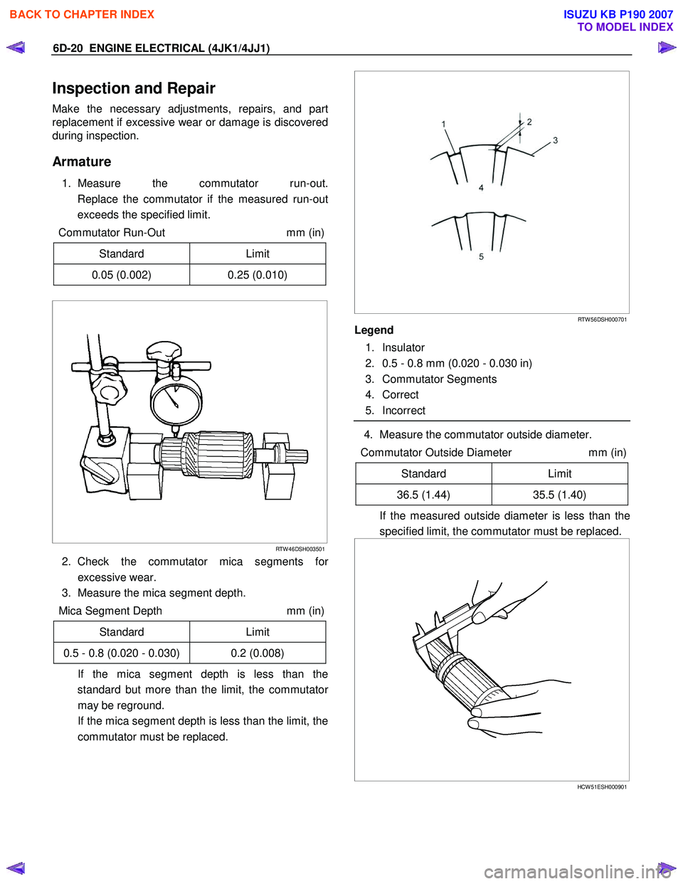
1. Measure the commutator run-out.
Replace the commutator if the measured run-out
exceeds the specified limit.
Commutator Run-Out mm (in)
Standard Limit
0.05 (0.002) 0.25 (0.010)
RTW 46DSH003501
2. Check the commutator mica segments for
excessive wear.
3. Measure the mica segment depth.
Mica Segment Depth mm (in)
Standard Limit
0.5 - 0.8 (0.020 - 0.030) 0.2 (0.008)
If the mica segment depth is less than the standard but more than the limit, the commutato
r
may be reground.
If the mica segment depth is less than the limit, the commutator must be replaced.
RTW 56DSH000701
Legend
1. Insulator
2. 0.5 - 0.8 mm (0.020 - 0.030 in)
3. Commutator Segments
4. Correct
5. Incorrect
4. Measure the commutator outside diameter.
Commutator Outside Diameter mm (in)
Standard Limit
36.5 (1.44) 35.5 (1.40)
If the measured outside diameter is less than the
specified limit, the commutator must be replaced.
HCW 51ESH000901
BACK TO CHAPTER INDEX
TO MODEL INDEX
ISUZU KB P190 2007
Page 1619 of 6020
6E-2 ENGINE CONTROL SYSTEM (4JK1/4JJ1)
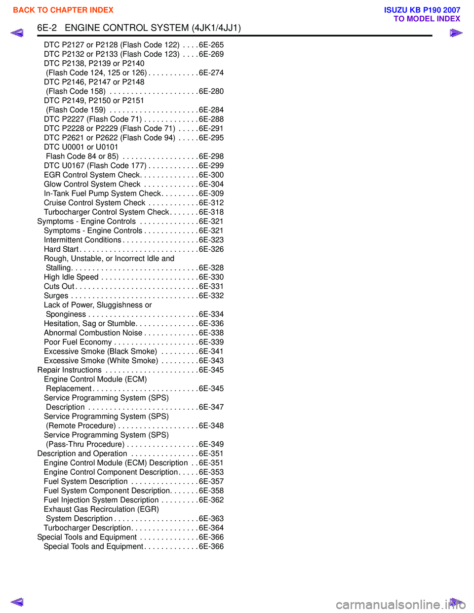
DTC P2127 or P2128 (Flash Code 122) . . . . 6E-265
DTC P2132 or P2133 (Flash Code 123) . . . . 6E-269
DTC P2138, P2139 or P2140 (Flash Code 124, 125 or 126) . . . . . . . . . . . . 6E-274
DTC P2146, P2147 or P2148 (Flash Code 158) . . . . . . . . . . . . . . . . . . . . . 6E-280
DTC P2149, P2150 or P2151 (Flash Code 159) . . . . . . . . . . . . . . . . . . . . . 6E-284
DTC P2227 (Flash Code 71) . . . . . . . . . . . . . 6E-288
DTC P2228 or P2229 (Flash Code 71) . . . . . 6E-291
DTC P2621 or P2622 (Flash Code 94) . . . . . 6E-295
DTC U0001 or U0101 Flash Code 84 or 85) . . . . . . . . . . . . . . . . . . 6E-298
DTC U0167 (Flash Code 177) . . . . . . . . . . . . 6E-299
EGR Control System Check. . . . . . . . . . . . . . 6E-300
Glow Control System Check . . . . . . . . . . . . . 6E-304
In-Tank Fuel Pump System Check . . . . . . . . . 6E-309
Cruise Control System Check . . . . . . . . . . . . 6E-312
Turbocharger Control System Check . . . . . . . 6E-318
Symptoms - Engine Controls . . . . . . . . . . . . . . 6E-321 Symptoms - Engine Controls . . . . . . . . . . . . . 6E-321
Intermittent Conditions . . . . . . . . . . . . . . . . . . 6E-323
Hard Start . . . . . . . . . . . . . . . . . . . . . . . . . . . . 6E-326
Rough, Unstable, or Incorrect Idle and Stalling. . . . . . . . . . . . . . . . . . . . . . . . . . . . . . 6E-328
High Idle Speed . . . . . . . . . . . . . . . . . . . . . . . 6E-330
Cuts Out . . . . . . . . . . . . . . . . . . . . . . . . . . . . . 6E-331
Surges . . . . . . . . . . . . . . . . . . . . . . . . . . . . . . 6E-332
Lack of Power, Sluggishness or Sponginess . . . . . . . . . . . . . . . . . . . . . . . . . . 6E-334
Hesitation, Sag or Stumble. . . . . . . . . . . . . . . 6E-336
Abnormal Combustion Noise . . . . . . . . . . . . . 6E-338
Poor Fuel Economy . . . . . . . . . . . . . . . . . . . . 6E-339
Excessive Smoke (Black Smoke) . . . . . . . . . 6E-341
Excessive Smoke (White Smoke) . . . . . . . . . 6E-343
Repair Instructions . . . . . . . . . . . . . . . . . . . . . . 6E-345 Engine Control Module (ECM) Replacement . . . . . . . . . . . . . . . . . . . . . . . . . 6E-345
Service Programming System (SPS) Description . . . . . . . . . . . . . . . . . . . . . . . . . . 6E-347
Service Programming System (SPS) (Remote Procedure) . . . . . . . . . . . . . . . . . . . 6E-348
Service Programming System (SPS) (Pass-Thru Procedure) . . . . . . . . . . . . . . . . . 6E-349
Description and Operation . . . . . . . . . . . . . . . . 6E-351 Engine Control Module (ECM) Description . . 6E-351
Engine Control Component Description . . . . . 6E-353
Fuel System Description . . . . . . . . . . . . . . . . 6E-357
Fuel System Component Description. . . . . . . 6E-358
Fuel Injection System Description . . . . . . . . . 6E-362
Exhaust Gas Recirculation (EGR) System Description . . . . . . . . . . . . . . . . . . . . 6E-363
Turbocharger Description . . . . . . . . . . . . . . . . 6E-364
Special Tools and Equipment . . . . . . . . . . . . . . 6E-366 Special Tools and Equipment . . . . . . . . . . . . . 6E-366
BACK TO CHAPTER INDEX
TO MODEL INDEX
ISUZU KB P190 2007
Page 1622 of 6020
ENGINE CONTROL SYSTEM (4JK1/4JJ1) 6E-5
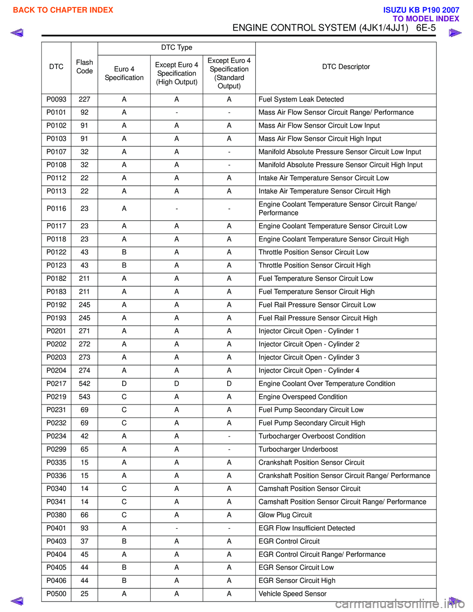
P0093 227 AAA Fuel System Leak Detected
P0101 92 A -- Mass Air Flow Sensor Circuit Range/ Performance
P0102 91 A AA Mass Air Flow Sensor Circuit Low Input
P0103 91 A AA Mass Air Flow Sensor Circuit High Input
P0107 32 A A- Manifold Absolute Pressure Sensor Circuit Low Input
P0108 32 A A- Manifold Absolute Pressure Sensor Circuit High Input
P0112 22 A AA Intake Air Temperature Sensor Circuit Low
P0113 22 A AA Intake Air Temperature Sensor Circuit High
P0116 23 A --Engine Coolant Temperature Sensor Circuit Range/
Performance
P0117 23 A AA Engine Coolant Temperature Sensor Circuit Low
P0118 23 A AA Engine Coolant Temperature Sensor Circuit High
P0122 43 B AA Throttle Position Sensor Circuit Low
P0123 43 B AA Throttle Position Sensor Circuit High
P0182 211 A AA Fuel Temperature Sensor Circuit Low
P0183 211 A AA Fuel Temperature Sensor Circuit High
P0192 245 A AA Fuel Rail Pressure Sensor Circuit Low
P0193 245 A AA Fuel Rail Pressure Sensor Circuit High
P0201 271 A AA Injector Circuit Open - Cylinder 1
P0202 272 A AA Injector Circuit Open - Cylinder 2
P0203 273 A AA Injector Circuit Open - Cylinder 3
P0204 274 A AA Injector Circuit Open - Cylinder 4
P0217 542 D DD Engine Coolant Over Temperature Condition
P0219 543 C AA Engine Overspeed Condition
P0231 69 C AA Fuel Pump Secondary Circuit Low
P0232 69 C AA Fuel Pump Secondary Circuit High
P0234 42 A A- Turbocharger Overboost Condition
P0299 65 A A- Turbocharger Underboost
P0335 15 A AA Crankshaft Position Sensor Circuit
P0336 15 A AA Crankshaft Position Sensor Circuit Range/ Performance
P0340 14 C AA Camshaft Position Sensor Circuit
P0341 14 C AA Camshaft Position Sensor Circuit Range/ Performance
P0380 66 C AA Glow Plug Circuit
P0401 93 A -- EGR Flow Insufficient Detected
P0403 37 B AA EGR Control Circuit
P0404 45 A AA EGR Control Circuit Range/ Performance
P0405 44 B AA EGR Sensor Circuit Low
P0406 44 B AA EGR Sensor Circuit High
P0500 25 A AA Vehicle Speed Sensor
DTC
Flash
Code DTC Type
DTC Descriptor
Euro 4
Specification Except Euro 4
Specification
(High Output) Except Euro 4
Specification (Standard Output)
BACK TO CHAPTER INDEX
TO MODEL INDEX
ISUZU KB P190 2007