2007 ISUZU KB P190 EGR
[x] Cancel search: EGRPage 1729 of 6020
6E-112 ENGINE CONTROL SYSTEM (4JK1/4JJ1)
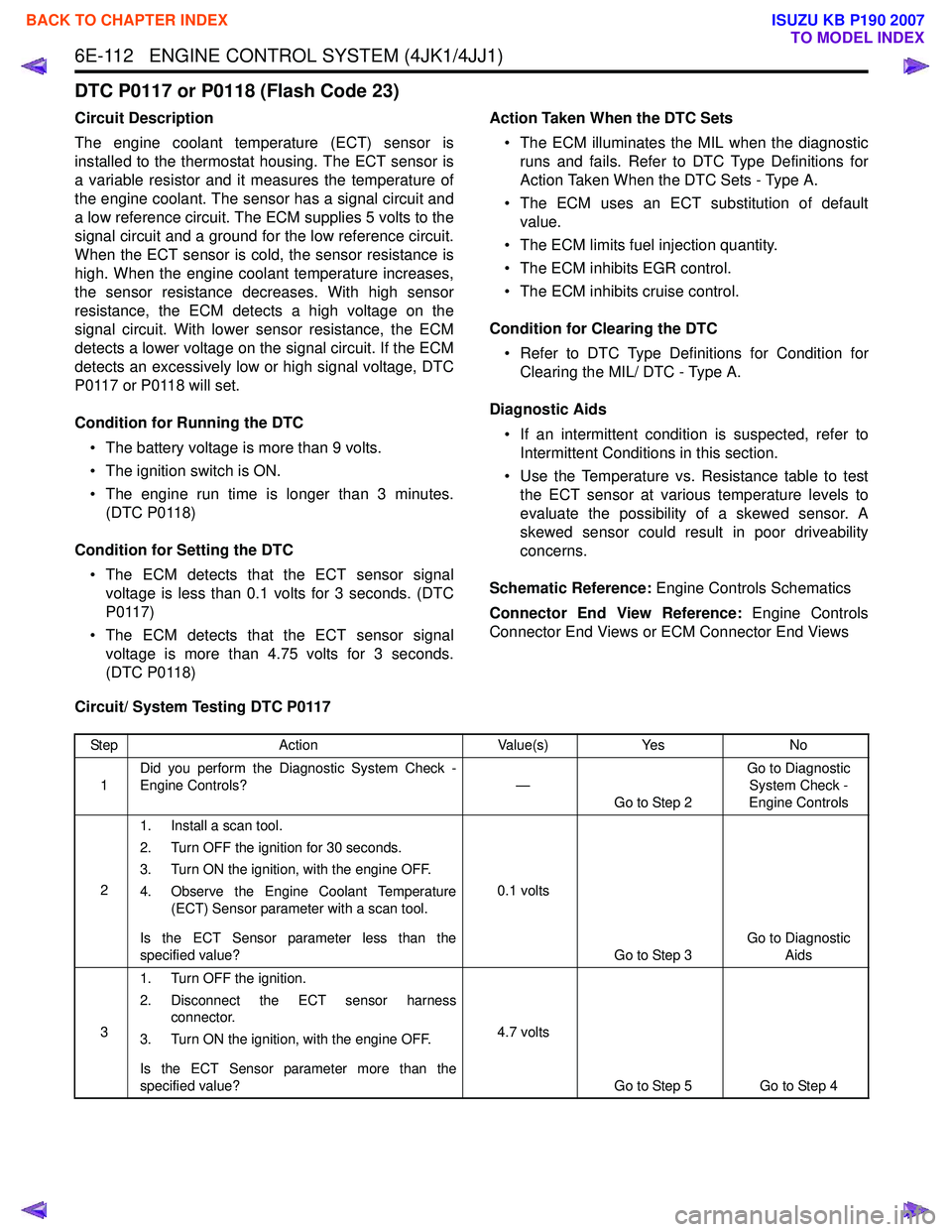
DTC P0117 or P0118 (Flash Code 23)
Circuit Description
The engine coolant temperature (ECT) sensor is
installed to the thermostat housing. The ECT sensor is
a variable resistor and it measures the temperature of
the engine coolant. The sensor has a signal circuit and
a low reference circuit. The ECM supplies 5 volts to the
signal circuit and a ground for the low reference circuit.
When the ECT sensor is cold, the sensor resistance is
high. When the engine coolant temperature increases,
the sensor resistance decreases. With high sensor
resistance, the ECM detects a high voltage on the
signal circuit. With lower sensor resistance, the ECM
detects a lower voltage on the signal circuit. If the ECM
detects an excessively low or high signal voltage, DTC
P0117 or P0118 will set.
Condition for Running the DTC • The battery voltage is more than 9 volts.
• The ignition switch is ON.
• The engine run time is longer than 3 minutes. (DTC P0118)
Condition for Setting the DTC • The ECM detects that the ECT sensor signal voltage is less than 0.1 volts for 3 seconds. (DTC
P0117)
• The ECM detects that the ECT sensor signal voltage is more than 4.75 volts for 3 seconds.
(DTC P0118) Action Taken When the DTC Sets
• The ECM illuminates the MIL when the diagnostic runs and fails. Refer to DTC Type Definitions for
Action Taken When the DTC Sets - Type A.
• The ECM uses an ECT substitution of default value.
• The ECM limits fuel injection quantity.
• The ECM inhibits EGR control.
• The ECM inhibits cruise control.
Condition for Clearing the DTC • Refer to DTC Type Definitions for Condition for Clearing the MIL/ DTC - Type A.
Diagnostic Aids • If an intermittent condition is suspected, refer to Intermittent Conditions in this section.
• Use the Temperature vs. Resistance table to test the ECT sensor at various temperature levels to
evaluate the possibility of a skewed sensor. A
skewed sensor could result in poor driveability
concerns.
Schematic Reference: Engine Controls Schematics
Connector End View Reference: Engine Controls
Connector End Views or ECM Connector End Views
Circuit/ System Testing DTC P0117
Step Action Value(s)Yes No
1 Did you perform the Diagnostic System Check -
Engine Controls? —
Go to Step 2 Go to Diagnostic
System Check -
Engine Controls
2 1. Install a scan tool.
2. Turn OFF the ignition for 30 seconds.
3. Turn ON the ignition, with the engine OFF.
4. Observe the Engine Coolant Temperature (ECT) Sensor parameter with a scan tool.
Is the ECT Sensor parameter less than the
specified value? 0.1 volts
Go to Step 3 Go to Diagnostic
Aids
3 1. Turn OFF the ignition.
2. Disconnect the ECT sensor harness connector.
3. Turn ON the ignition, with the engine OFF.
Is the ECT Sensor parameter more than the
specified value? 4.7 volts
Go to Step 5 Go to Step 4
BACK TO CHAPTER INDEX
TO MODEL INDEX
ISUZU KB P190 2007
Page 1733 of 6020
6E-116 ENGINE CONTROL SYSTEM (4JK1/4JJ1)
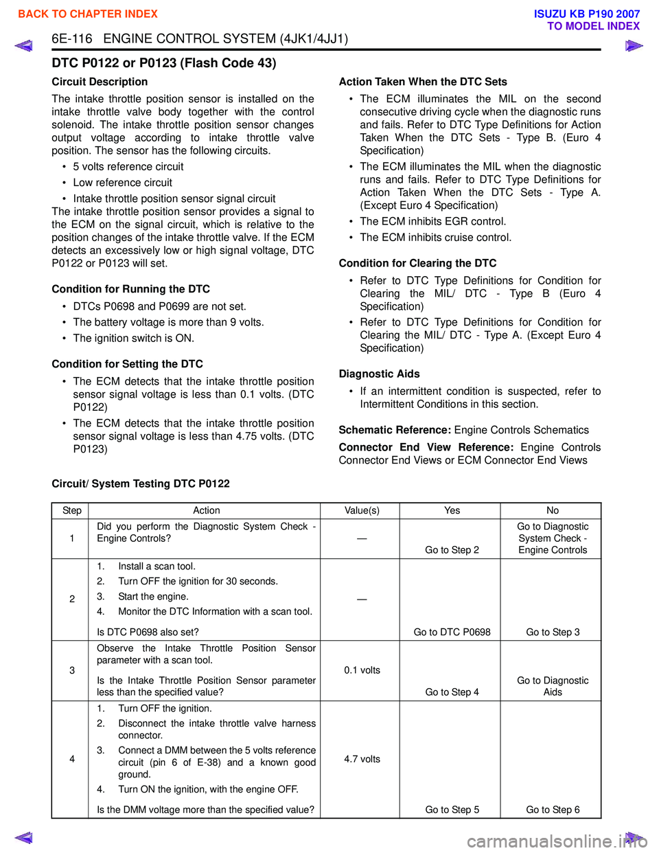
DTC P0122 or P0123 (Flash Code 43)
Circuit Description
The intake throttle position sensor is installed on the
intake throttle valve body together with the control
solenoid. The intake throttle position sensor changes
output voltage according to intake throttle valve
position. The sensor has the following circuits.
• 5 volts reference circuit
• Low reference circuit
• Intake throttle position sensor signal circuit
The intake throttle position sensor provides a signal to
the ECM on the signal circuit, which is relative to the
position changes of the intake throttle valve. If the ECM
detects an excessively low or high signal voltage, DTC
P0122 or P0123 will set.
Condition for Running the DTC • DTCs P0698 and P0699 are not set.
• The battery voltage is more than 9 volts.
• The ignition switch is ON.
Condition for Setting the DTC • The ECM detects that the intake throttle position sensor signal voltage is less than 0.1 volts. (DTC
P0122)
• The ECM detects that the intake throttle position sensor signal voltage is less than 4.75 volts. (DTC
P0123) Action Taken When the DTC Sets
• The ECM illuminates the MIL on the second consecutive driving cycle when the diagnostic runs
and fails. Refer to DTC Type Definitions for Action
Taken When the DTC Sets - Type B. (Euro 4
Specification)
• The ECM illuminates the MIL when the diagnostic runs and fails. Refer to DTC Type Definitions for
Action Taken When the DTC Sets - Type A.
(Except Euro 4 Specification)
• The ECM inhibits EGR control.
• The ECM inhibits cruise control.
Condition for Clearing the DTC • Refer to DTC Type Definitions for Condition for Clearing the MIL/ DTC - Type B (Euro 4
Specification)
• Refer to DTC Type Definitions for Condition for Clearing the MIL/ DTC - Type A. (Except Euro 4
Specification)
Diagnostic Aids • If an intermittent condition is suspected, refer to Intermittent Conditions in this section.
Schematic Reference: Engine Controls Schematics
Connector End View Reference: Engine Controls
Connector End Views or ECM Connector End Views
Circuit/ System Testing DTC P0122
Step Action Value(s)Yes No
1 Did you perform the Diagnostic System Check -
Engine Controls? —
Go to Step 2 Go to Diagnostic
System Check -
Engine Controls
2 1. Install a scan tool.
2. Turn OFF the ignition for 30 seconds.
3. Start the engine.
4. Monitor the DTC Information with a scan tool.
Is DTC P0698 also set? —
Go to DTC P0698 Go to Step 3
3 Observe the Intake Throttle Position Sensor
parameter with a scan tool.
Is the Intake Throttle Position Sensor parameter
less than the specified value? 0.1 volts
Go to Step 4 Go to Diagnostic
Aids
4 1. Turn OFF the ignition.
2. Disconnect the intake throttle valve harness connector.
3. Connect a DMM between the 5 volts reference circuit (pin 6 of E-38) and a known good
ground.
4. Turn ON the ignition, with the engine OFF.
Is the DMM voltage more than the specified value? 4.7 volts
Go to Step 5 Go to Step 6
BACK TO CHAPTER INDEX
TO MODEL INDEX
ISUZU KB P190 2007
Page 1759 of 6020
6E-142 ENGINE CONTROL SYSTEM (4JK1/4JJ1)
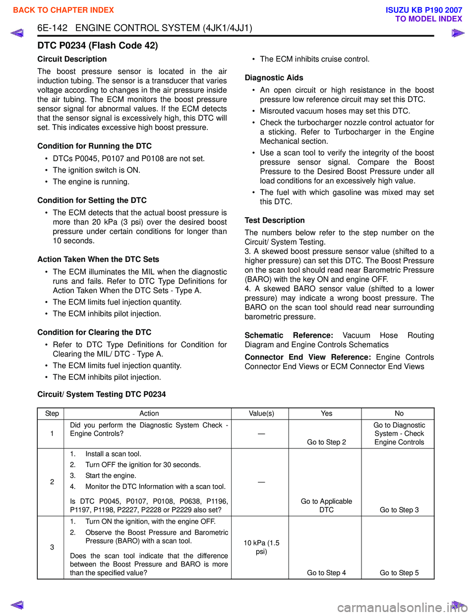
DTC P0234 (Flash Code 42)
Circuit Description
The boost pressure sensor is located in the air
induction tubing. The sensor is a transducer that varies
voltage according to changes in the air pressure inside
the air tubing. The ECM monitors the boost pressure
sensor signal for abnormal values. If the ECM detects
that the sensor signal is excessively high, this DTC will
set. This indicates excessive high boost pressure.
Condition for Running the DTC • DTCs P0045, P0107 and P0108 are not set.
• The ignition switch is ON.
• The engine is running.
Condition for Setting the DTC • The ECM detects that the actual boost pressure is more than 20 kPa (3 psi) over the desired boost
pressure under certain conditions for longer than
10 seconds.
Action Taken When the DTC Sets • The ECM illuminates the MIL when the diagnostic runs and fails. Refer to DTC Type Definitions for
Action Taken When the DTC Sets - Type A.
• The ECM limits fuel injection quantity.
• The ECM inhibits pilot injection.
Condition for Clearing the DTC • Refer to DTC Type Definitions for Condition for Clearing the MIL/ DTC - Type A.
• The ECM limits fuel injection quantity.
• The ECM inhibits pilot injection. • The ECM inhibits cruise control.
Diagnostic Aids • An open circuit or high resistance in the boost pressure low reference circuit may set this DTC.
• Misrouted vacuum hoses may set this DTC.
• Check the turbocharger nozzle control actuator for a sticking. Refer to Turbocharger in the Engine
Mechanical section.
• Use a scan tool to verify the integrity of the boost pressure sensor signal. Compare the Boost
Pressure to the Desired Boost Pressure under all
load conditions for an excessively high value.
• The fuel with which gasoline was mixed may set this DTC.
Test Description
The numbers below refer to the step number on the
Circuit/ System Testing.
3. A skewed boost pressure sensor value (shifted to a
higher pressure) can set this DTC. The Boost Pressure
on the scan tool should read near Barometric Pressure
(BARO) with the key ON and engine OFF.
4. A skewed BARO sensor value (shifted to a lower
pressure) may indicate a wrong boost pressure. The
BARO on the scan tool should read near surrounding
barometric pressure.
Schematic Reference: Vacuum Hose Routing
Diagram and Engine Controls Schematics
Connector End View Reference: Engine Controls
Connector End Views or ECM Connector End Views
Circuit/ System Testing DTC P0234
Step Action Value(s)Yes No
1 Did you perform the Diagnostic System Check -
Engine Controls? —
Go to Step 2 Go to Diagnostic
System - Check
Engine Controls
2 1. Install a scan tool.
2. Turn OFF the ignition for 30 seconds.
3. Start the engine.
4. Monitor the DTC Information with a scan tool.
Is DTC P0045, P0107, P0108, P0638, P1196,
P1197, P1198, P2227, P2228 or P2229 also set? —
Go to Applicable DTC Go to Step 3
3 1. Turn ON the ignition, with the engine OFF.
2. Observe the Boost Pressure and Barometric Pressure (BARO) with a scan tool.
Does the scan tool indicate that the difference
between the Boost Pressure and BARO is more
than the specified value? 10 kPa (1.5
psi)
Go to Step 4 Go to Step 5
BACK TO CHAPTER INDEX
TO MODEL INDEX
ISUZU KB P190 2007
Page 1762 of 6020
ENGINE CONTROL SYSTEM (4JK1/4JJ1) 6E-145
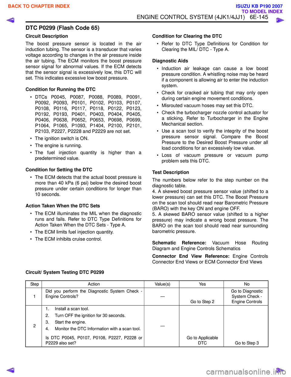
DTC P0299 (Flash Code 65)
Circuit Description
The boost pressure sensor is located in the air
induction tubing. The sensor is a transducer that varies
voltage according to changes in the air pressure inside
the air tubing. The ECM monitors the boost pressure
sensor signal for abnormal values. If the ECM detects
that the sensor signal is excessively low, this DTC will
set. This indicates excessive low boost pressure.
Condition for Running the DTC • DTCs P0045, P0087, P0088, P0089, P0091, P0092, P0093, P0101, P0102, P0103, P0107,
P0108, P0116, P0117, P0118, P0122, P0123,
P0192, P0193, P0401, P0403, P0404, P0405,
P0406, P0638, P0652, P0653, P0698, P0699,
P1064, P1065, P1093, P1404, P2100, P2101,
P2103, P2227, P2228 and P2229 are not set.
• The ignition switch is ON.
• The engine is running.
• The fuel injection quantity is higher than a predetermined value.
Condition for Setting the DTC • The ECM detects that the actual boost pressure is more than 40 kPa (6 psi) below the desired boost
pressure under certain conditions for longer than
10 seconds.
Action Taken When the DTC Sets • The ECM illuminates the MIL when the diagnostic runs and fails. Refer to DTC Type Definitions for
Action Taken When the DTC Sets - Type A.
• The ECM limits fuel injection quantity.
• The ECM inhibits cruise control. Condition for Clearing the DTC
• Refer to DTC Type Definitions for Condition for Clearing the MIL/ DTC - Type A.
Diagnostic Aids • Induction air leakage can cause a low boost pressure condition. A whistling noise may be heard
if a component is allowing air to enter the induction
system.
• Check for cracked air tubing that may only open during certain engine movement conditions.
• Misrouted vacuum hoses may set this DTC.
• Check the turbocharger nozzle control actuator for a sticking. Refer to Turbocharger in the Engine
Mechanical section.
• Use a scan tool to verify the integrity of the boost pressure sensor signal. Compare the Boost
Pressure to the Desired Boost Pressure under all
load conditions for an excessively low value.
• Loss of vacuum pressure or vacuum pump problem sets this DTC.
Test Description
The numbers below refer to the step number on the
diagnostic table.
4. A skewed boost pressure sensor value (shifted to a
lower pressure) can set this DTC. The Boost Pressure
on the scan tool should read near Barometric Pressure
(BARO) with the key ON and engine OFF.
5. A skewed BARO sensor value (shifted to a higher
pressure) may indicate a wrong boost pressure. The
BARO on the scan tool should read near surrounding
barometric pressure.
Schematic Reference: Vacuum Hose Routing
Diagram and Engine Controls Schematics
Connector End View Reference: Engine Controls
Connector End Views or ECM Connector End Views
Circuit/ System Testing DTC P0299
Step Action Value(s)Yes No
1 Did you perform the Diagnostic System Check -
Engine Controls? —
Go to Step 2 Go to Diagnostic
System Check -
Engine Controls
2 1. Install a scan tool.
2. Turn OFF the ignition for 30 seconds.
3. Start the engine.
4. Monitor the DTC Information with a scan tool.
Is DTC P0045, P0107, P0108, P2227, P2228 or
P2229 also set? —
Go to Applicable DTC Go to Step 3
BACK TO CHAPTER INDEX
TO MODEL INDEX
ISUZU KB P190 2007
Page 1778 of 6020
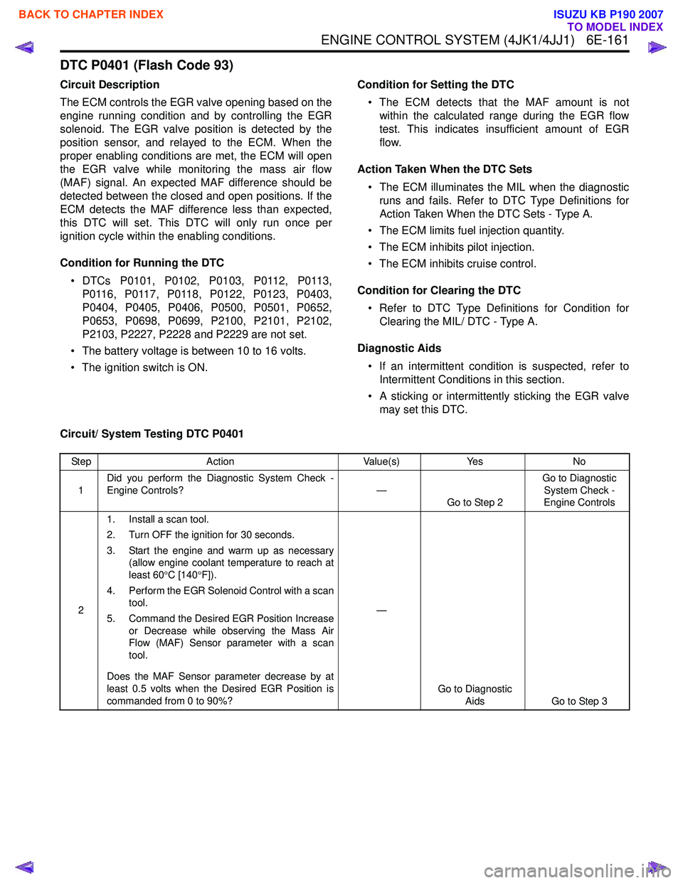
ENGINE CONTROL SYSTEM (4JK1/4JJ1) 6E-161
DTC P0401 (Flash Code 93)
Circuit Description
The ECM controls the EGR valve opening based on the
engine running condition and by controlling the EGR
solenoid. The EGR valve position is detected by the
position sensor, and relayed to the ECM. When the
proper enabling conditions are met, the ECM will open
the EGR valve while monitoring the mass air flow
(MAF) signal. An expected MAF difference should be
detected between the closed and open positions. If the
ECM detects the MAF difference less than expected,
this DTC will set. This DTC will only run once per
ignition cycle within the enabling conditions.
Condition for Running the DTC • DTCs P0101, P0102, P0103, P0112, P0113, P0116, P0117, P0118, P0122, P0123, P0403,
P0404, P0405, P0406, P0500, P0501, P0652,
P0653, P0698, P0699, P2100, P2101, P2102,
P2103, P2227, P2228 and P2229 are not set.
• The battery voltage is between 10 to 16 volts.
• The ignition switch is ON. Condition for Setting the DTC
• The ECM detects that the MAF amount is not within the calculated range during the EGR flow
test. This indicates insufficient amount of EGR
flow.
Action Taken When the DTC Sets • The ECM illuminates the MIL when the diagnostic runs and fails. Refer to DTC Type Definitions for
Action Taken When the DTC Sets - Type A.
• The ECM limits fuel injection quantity.
• The ECM inhibits pilot injection.
• The ECM inhibits cruise control.
Condition for Clearing the DTC • Refer to DTC Type Definitions for Condition for Clearing the MIL/ DTC - Type A.
Diagnostic Aids • If an intermittent condition is suspected, refer to Intermittent Conditions in this section.
• A sticking or intermittently sticking the EGR valve may set this DTC.
Circuit/ System Testing DTC P0401
Step Action Value(s)Yes No
1 Did you perform the Diagnostic System Check -
Engine Controls? —
Go to Step 2 Go to Diagnostic
System Check -
Engine Controls
2 1. Install a scan tool.
2. Turn OFF the ignition for 30 seconds.
3. Start the engine and warm up as necessary (allow engine coolant temperature to reach at
least 60 °C [140 °F]).
4. Perform the EGR Solenoid Control with a scan tool.
5. Command the Desired EGR Position Increase or Decrease while observing the Mass Air
Flow (MAF) Sensor parameter with a scan
tool.
Does the MAF Sensor parameter decrease by at
least 0.5 volts when the Desired EGR Position is
commanded from 0 to 90%? —
Go to Diagnostic Aids Go to Step 3
BACK TO CHAPTER INDEX
TO MODEL INDEX
ISUZU KB P190 2007
Page 1779 of 6020
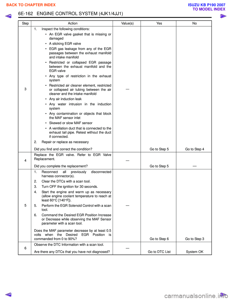
6E-162 ENGINE CONTROL SYSTEM (4JK1/4JJ1)
31. Inspect the following conditions:
• An EGR valve gasket that is missing ordamaged
• A sticking EGR valve
• EGR gas leakage from any of the EGR passages between the exhaust manifold
and intake manifold
• Restricted or collapsed EGR passage between the exhaust manifold and the
EGR valve
• Any type of restriction in the exhaust system
• Restricted air cleaner element, restricted or collapsed air tubing between the air
cleaner and the intake manifold
• Any air induction leak
• Any water intrusion in the induction system
• Any contamination or objects that block the MAF sensor inlet
• Skewed or slow MAF sensor
• A ventilation duct that is connected to the exhaust tail pipe. Retest without the duct
if connected.
2. Repair or replace as necessary
Did you find and correct the condition? —
Go to Step 5 Go to Step 4
4 Replace the EGR valve. Refer to EGR Valve
Replacement.
Did you complete the replacement? —
Go to Step 5
—
51. Reconnect all previously disconnected
harness connector(s).
2. Clear the DTCs with a scan tool.
3. Turn OFF the ignition for 30 seconds.
4. Start the engine and warm up as necessary (allow engine coolant temperature to reach at
least 60 °C [140 °F]).
5. Perform the EGR Solenoid Control with a scan tool.
6. Command the Desired EGR Position Increase or Decrease while observing the MAF Sensor
parameter with a scan tool.
Does the MAF parameter decrease by at least 0.5
volts when the Desired EGR Position is
commanded from 0 to 90%? —
Go to Step 6 Go to Step 3
6 Observe the DTC Information with a scan tool.
Are there any DTCs that you have not diagnosed? —
Go to DTC List System OK
Step
Action Value(s)Yes No
BACK TO CHAPTER INDEX
TO MODEL INDEX
ISUZU KB P190 2007
Page 1780 of 6020
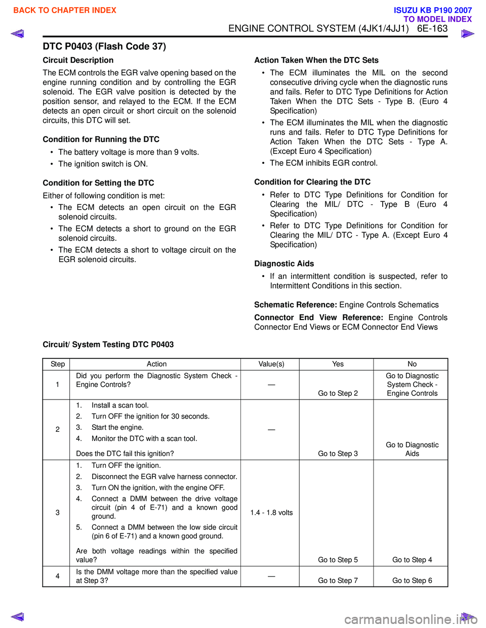
ENGINE CONTROL SYSTEM (4JK1/4JJ1) 6E-163
DTC P0403 (Flash Code 37)
Circuit Description
The ECM controls the EGR valve opening based on the
engine running condition and by controlling the EGR
solenoid. The EGR valve position is detected by the
position sensor, and relayed to the ECM. If the ECM
detects an open circuit or short circuit on the solenoid
circuits, this DTC will set.
Condition for Running the DTC • The battery voltage is more than 9 volts.
• The ignition switch is ON.
Condition for Setting the DTC
Either of following condition is met: • The ECM detects an open circuit on the EGR solenoid circuits.
• The ECM detects a short to ground on the EGR solenoid circuits.
• The ECM detects a short to voltage circuit on the EGR solenoid circuits. Action Taken When the DTC Sets
• The ECM illuminates the MIL on the second consecutive driving cycle when the diagnostic runs
and fails. Refer to DTC Type Definitions for Action
Taken When the DTC Sets - Type B. (Euro 4
Specification)
• The ECM illuminates the MIL when the diagnostic runs and fails. Refer to DTC Type Definitions for
Action Taken When the DTC Sets - Type A.
(Except Euro 4 Specification)
• The ECM inhibits EGR control.
Condition for Clearing the DTC • Refer to DTC Type Definitions for Condition for Clearing the MIL/ DTC - Type B (Euro 4
Specification)
• Refer to DTC Type Definitions for Condition for Clearing the MIL/ DTC - Type A. (Except Euro 4
Specification)
Diagnostic Aids • If an intermittent condition is suspected, refer to Intermittent Conditions in this section.
Schematic Reference: Engine Controls Schematics
Connector End View Reference: Engine Controls
Connector End Views or ECM Connector End Views
Circuit/ System Testing DTC P0403
Step Action Value(s)Yes No
1 Did you perform the Diagnostic System Check -
Engine Controls? —
Go to Step 2 Go to Diagnostic
System Check -
Engine Controls
2 1. Install a scan tool.
2. Turn OFF the ignition for 30 seconds.
3. Start the engine.
4. Monitor the DTC with a scan tool.
Does the DTC fail this ignition? —
Go to Step 3 Go to Diagnostic
Aids
3 1. Turn OFF the ignition.
2. Disconnect the EGR valve harness connector.
3. Turn ON the ignition, with the engine OFF.
4. Connect a DMM between the drive voltage circuit (pin 4 of E-71) and a known good
ground.
5. Connect a DMM between the low side circuit (pin 6 of E-71) and a known good ground.
Are both voltage readings within the specified
value? 1.4 - 1.8 volts
Go to Step 5 Go to Step 4
4 Is the DMM voltage more than the specified value
at Step 3? —
Go to Step 7 Go to Step 6
BACK TO CHAPTER INDEX
TO MODEL INDEX
ISUZU KB P190 2007
Page 1781 of 6020
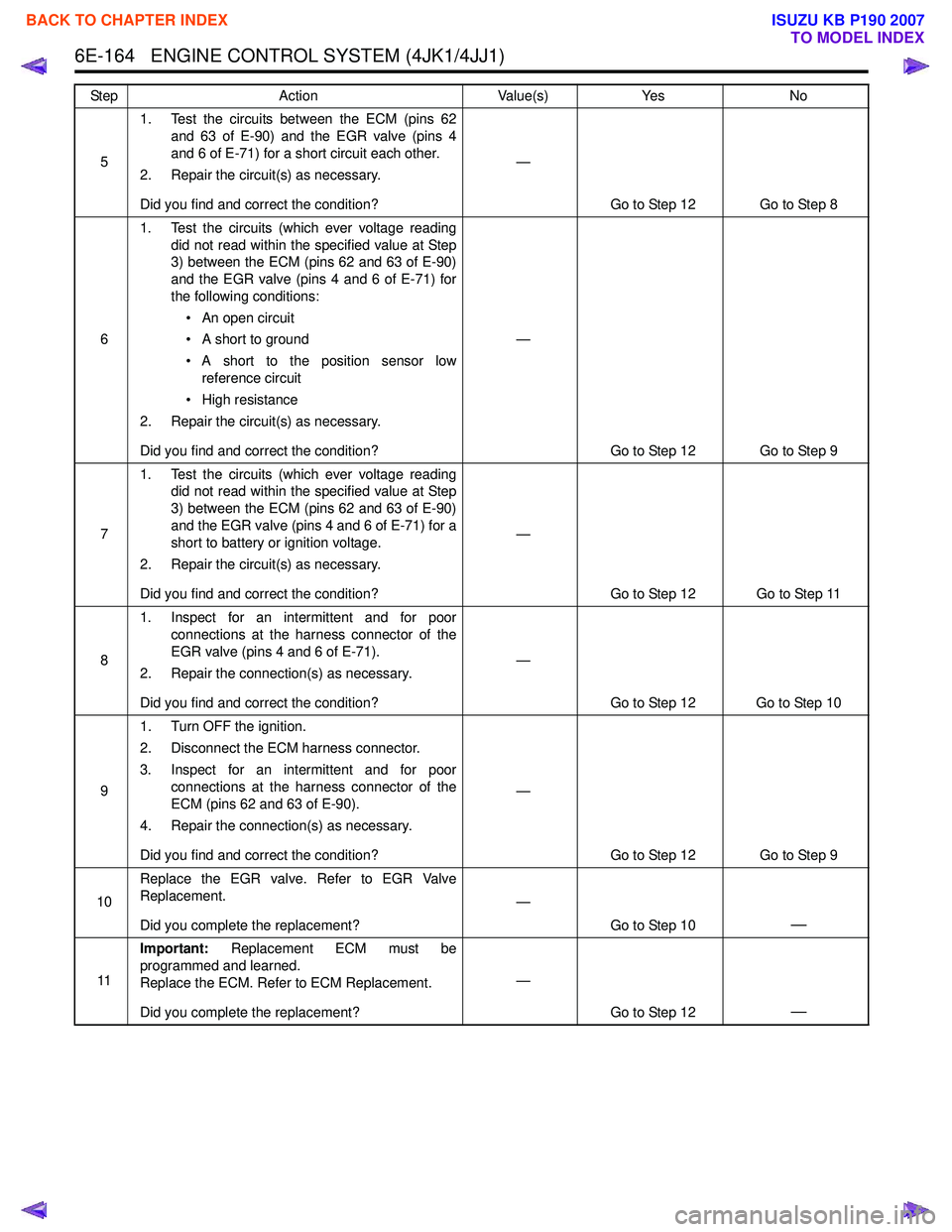
6E-164 ENGINE CONTROL SYSTEM (4JK1/4JJ1)
51. Test the circuits between the ECM (pins 62
and 63 of E-90) and the EGR valve (pins 4
and 6 of E-71) for a short circuit each other.
2. Repair the circuit(s) as necessary.
Did you find and correct the condition? —
Go to Step 12 Go to Step 8
6 1. Test the circuits (which ever voltage reading
did not read within the specified value at Step
3) between the ECM (pins 62 and 63 of E-90)
and the EGR valve (pins 4 and 6 of E-71) for
the following conditions:
• An open circuit
• A short to ground
• A short to the position sensor low reference circuit
• High resistance
2. Repair the circuit(s) as necessary.
Did you find and correct the condition? —
Go to Step 12 Go to Step 9
7 1. Test the circuits (which ever voltage reading
did not read within the specified value at Step
3) between the ECM (pins 62 and 63 of E-90)
and the EGR valve (pins 4 and 6 of E-71) for a
short to battery or ignition voltage.
2. Repair the circuit(s) as necessary.
Did you find and correct the condition? —
Go to Step 12 Go to Step 11
8 1. Inspect for an intermittent and for poor
connections at the harness connector of the
EGR valve (pins 4 and 6 of E-71).
2. Repair the connection(s) as necessary.
Did you find and correct the condition? —
Go to Step 12 Go to Step 10
9 1. Turn OFF the ignition.
2. Disconnect the ECM harness connector.
3. Inspect for an intermittent and for poor connections at the harness connector of the
ECM (pins 62 and 63 of E-90).
4. Repair the connection(s) as necessary.
Did you find and correct the condition? —
Go to Step 12 Go to Step 9
10 Replace the EGR valve. Refer to EGR Valve
Replacement.
Did you complete the replacement? —
Go to Step 10
—
11Important:
Replacement ECM must be
programmed and learned.
Replace the ECM. Refer to ECM Replacement.
Did you complete the replacement? —
Go to Step 12
—
Step Action Value(s)Yes No
BACK TO CHAPTER INDEX
TO MODEL INDEX
ISUZU KB P190 2007