2007 ISUZU KB P190 EGR
[x] Cancel search: EGRPage 1669 of 6020
6E-52 ENGINE CONTROL SYSTEM (4JK1/4JJ1)
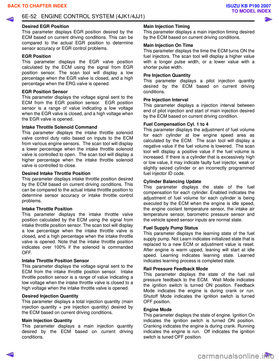
Desired EGR Position
This parameter displays EGR position desired by the
ECM based on current driving conditions. This can be
compared to the actual EGR position to determine
sensor accuracy or EGR control problems.
EGR Position
This parameter displays the EGR valve position
calculated by the ECM using the signal from EGR
position sensor. The scan tool will display a low
percentage when the EGR valve is closed, and a high
percentage when the ERG valve is opened.
EGR Position Sensor
This parameter displays the voltage signal sent to the
ECM from the EGR position sensor. EGR position
sensor is a range of value indicating a low voltage
when the EGR valve is closed, and a high voltage when
the EGR valve is opened.
Intake Throttle Solenoid Command
This parameter displays the intake throttle solenoid
valve control duty ratio based on inputs to the ECM
from various engine sensors. The scan tool will display
a lower percentage when the intake throttle solenoid
valve is controlled to open. The scan tool will display a
higher percentage when the intake throttle solenoid
valve is controlled to close.
Desired Intake Throttle Position
This parameter displays intake throttle position desired
by the ECM based on current driving conditions. This
can be compared to the actual intake throttle position to
determine sensor accuracy or intake throttle control
problems.
Intake Throttle Position
This parameter displays the intake throttle valve
position calculated by the ECM using the signal from
intake throttle position sensor. The scan tool will display
a low percentage when the intake throttle valve is
closed, and a high percentage when the intake throttle
valve is opened. Note that the intake throttle position
indicates over 100% if the solenoid is commanded
OFF.
Intake Throttle Position Sensor
This parameter displays the voltage signal sent to the
ECM from the intake throttle position sensor. Intake
throttle position sensor is a range of value indicating a
low voltage when the intake throttle valve is closed to a
high voltage when the intake throttle valve is opened.
Desired Injection Quantity
This parameter displays a total injection quantity (main
injection quantity + pre injection quantity) desired by
the ECM based on current driving conditions.
Main Injection Quantity
This parameter displays a main injection quantity
desired by the ECM based on current driving
conditions. Main Injection Timing
This parameter displays a main injection timing desired
by the ECM based on current driving conditions.
Main Injection On Time
This parameter displays the time the ECM turns ON the
fuel injectors. The scan tool will display a higher value
with a longer pulse width, or a lower value with a
shorter pulse width.
Pre Injection Quantity
This parameter displays a pilot injection quantity
desired by the ECM based on current driving
conditions.
Pre Injection Interval
This parameter displays a injection interval between
end of pilot injection and start of main injection desired
by the ECM based on current driving condition.
Fuel Compensation Cyl. 1 to 4
This parameter displays the adjustment of fuel volume
for each cylinder at low engine speed area as
calculated by the ECM. The scan tool will display a
negative value if the fuel volume is lowered. The scan
tool will display a positive value if the fuel volume is
increased. If there is a cylinder that is excessively high
or low value, it may indicate faulty fuel injector, weak or
slightly seized cylinder or an incorrectly programmed
fuel injector ID code.
Cylinder Balancing Update
This parameter displays the state of the fuel
compensation for each cylinder. Enabled indicates the
adjustment of fuel volume for each cylinder is being
executed by the ECM when the engine is idle speed,
the engine coolant temperature sensor, the intake air
temperature sensor, barometric pressure sensor and
the vehicle speed sensor inputs are normal state.
Fuel Supply Pump Status
This parameter displays the learning state of the fuel
supply pump. Not Learn indicates initialized state that is
replaced to a new ECM or adjustment value is reset.
After engine is warm upped, leaning will start at idle
speed. Learning indicates learning state. Learned
indicates learning process is completed state.
Rail Pressure Feedback Mode
This parameter displays the state of the fuel rail
pressure feedback to the ECM. Wait Mode indicates
the ignition switch is turned ON position. Feedback
Mode indicates the engine is during crank or run.
Shutoff Mode indicates the ignition switch is turned
OFF position.
Engine Mode
This parameter displays the state of engine. Ignition On
indicates the ignition switch is turned ON position.
Cranking indicates the engine is during crank. Running
indicates the engine is run. Off indicates the ignition
switch is tuned OFF position.
BACK TO CHAPTER INDEX
TO MODEL INDEX
ISUZU KB P190 2007
Page 1672 of 6020

ENGINE CONTROL SYSTEM (4JK1/4JJ1) 6E-55
Scan Tool Output Controls
Scan Tool Output ControlDescriptions
Fuel Supply Pump Learn Resetting The purpose of this test to reset the fuel supply pump adjustment value.
Important: The fuel supply pump relearn procedure must be done when the fuel supply
pump or engine is replaced, or an ECM from another vehicle is installed. Refer to Fuel
Supply Pump Replacement.
Fuel Pressure Control The purpose of this test is for checking whether the fuel rail pressure is changing when
commanded within 30 to 80MPa (4,350 to 11,600psi) when commanded. Faulty fuel supply
pump, fuel rail pressure (FRP) regulator, pressure limiter valve or other fuel lines could be
considered if the differential fuel rail pressure is large.
Pilot Injection Control The purpose of this test is for checking whether the pilot fuel injection is operated when it is
commanded to ON/ OFF. Faulty injector(s) could be considered if engine noise does not
change when commanded OFF.
Injection Timing Control The purpose of this test is for checking whether the main injection timing is changing when
commanded Retard/ Advance within -5 to 5 °CA.
Injector Force Drive The purpose of this test is for checking whether the fuel injector is correctly operating when
commanded ON. Faulty injector(s) could be considered if it does not create a clicking noise
(solenoid operating noise), contains an interrupted noise or has abnormal noise when
commanded ON.
Cylinder Balance Test The purpose of this test is for checking whether the fuel injector is operating when
commanded ON/ OFF. Faulty injector(s) could be considered if engine does not change
speed when commanded OFF.
Intake Throttle Solenoid Control The purpose of this test is for checking whether the intake throttle valve is correctly moved
with command. Restricted valve movement by foreign materials, excessive deposits or a
faulty valve could be considered if the position difference is large.
EGR Solenoid Control The purpose of this test is for checking whether the EGR valve is correctly moved with
command. Restricted valve movement by foreign materials, excessive deposits or a faulty
valve could be considered if the position difference is large.
Swirl Control Solenoid Control The purpose of this test is for checking whether the swirl control solenoid is operating when
commanded ON. Faulty circuit(s) or a faulty solenoid could be considered if not energizing
when commanded ON.
Turbocharger Solenoid Control The purpose of this test is for checking whether the turbocharger nozzle control actuator is
correctly moved with command. Restricted actuator movement by foreign materials,
excessive deposits, misrouted vacuum hoses, a faulty solenoid or a faulty actuator could be
considered if the actuator is not moved correctly.
Glow Relay Control The purpose of this test is for checking whether the glow relay is operating when
commanded ON. Faulty circuit(s) or a faulty glow relay could be considered if not energizing
when commanded ON.
Glow Plug Lamp Control The purpose of this test is for checking whether the glow indicator lamp is operating when
commanded ON. Faulty circuit(s) or an open circuit could be considered when not operating
when commanded ON.
Malfunction Indicator Lamp (MIL) Control The purpose of this test is for checking whether the MIL is operating when commanded ON.
Faulty circuit(s) or an open circuit could be considered when not operating when
commanded ON.
Service Vehicle Soon (SVS) Lamp Control The purpose of this test is for checking whether the SVS lamp is operating when
commanded ON. Faulty circuit(s) or an open circuit could be considered when not operating
when commanded ON.
Cruise Main Lamp Control The purpose of this test is for checking whether the cruise main lamp is operating when
commanded ON. Faulty circuit(s) or an open circuit could be considered when not operating
when commanded ON.
Cruise Set Lamp Control The purpose of this test is for checking whether the cruise set lamp is operating when
commanded ON. Faulty circuit(s) or an open circuit could be considered when not operating
when commanded ON.
BACK TO CHAPTER INDEX
TO MODEL INDEX
ISUZU KB P190 2007
Page 1712 of 6020
ENGINE CONTROL SYSTEM (4JK1/4JJ1) 6E-95
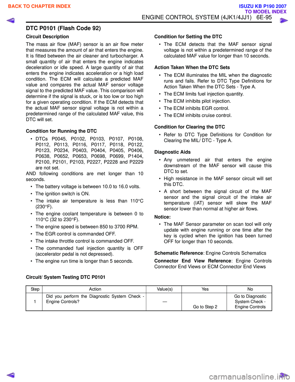
DTC P0101 (Flash Code 92)
Circuit Description
The mass air flow (MAF) sensor is an air flow meter
that measures the amount of air that enters the engine.
It is fitted between the air cleaner and turbocharger. A
small quantity of air that enters the engine indicates
deceleration or idle speed. A large quantity of air that
enters the engine indicates acceleration or a high load
condition. The ECM will calculate a predicted MAF
value and compares the actual MAF sensor voltage
signal to the predicted MAF value. This comparison will
determine if the signal is stuck, or is too low or too high
for a given operating condition. If the ECM detects that
the actual MAF sensor signal voltage is not within a
predetermined range of the calculated MAF value, this
DTC will set.
Condition for Running the DTC • DTCs P0045, P0102, P0103, P0107, P0108, P 0 11 2 , P 0 11 3 , P 0 11 6 , P 0 11 7 , P 0 11 8 , P 0 1 2 2 ,
P0123, P0234, P0403, P0404, P0405, P0406,
P0638, P0652, P0653, P0698, P0699, P1404,
P2100, P2101, P2103, P2227, P2228 and P2229
are not set.
AND following conditions are met longer than 10
seconds.
• The battery voltage is between 10.0 to 16.0 volts.
• The ignition switch is ON.
• The intake air temperature is less than 110 °C
(230 °F).
• The engine coolant temperature is between 0 to 11 0 °C (32 to 230 °F).
• The engine speed is between 850 to 3700 RPM.
• The EGR control is commanded OFF.
• The intake throttle control is commanded OFF.
• The commanded fuel injection quantity is OFF (accelerator pedal is not depressed).
• The engine run time is longer than 5 seconds. Condition for Setting the DTC
• The ECM detects that the MAF sensor signal voltage is not within a predetermined range of the
calculated MAF value for longer than 10 seconds.
Action Taken When the DTC Sets • The ECM illuminates the MIL when the diagnostic runs and fails. Refer to DTC Type Definitions for
Action Taken When the DTC Sets - Type A.
• The ECM limits fuel injection quantity.
• The ECM inhibits pilot injection.
• The ECM inhibits EGR control.
• The ECM inhibits cruise control.
Condition for Clearing the DTC • Refer to DTC Type Definitions for Condition for Clearing the MIL/ DTC - Type A.
Diagnostic Aids • Any unmetered air that enters the engine downstream of the MAF sensor will cause this
DTC to set.
• High resistance in the MAF sensor circuit will set this DTC.
• A short between the signal circuit of the MAF sensor and the signal circuit of the intake air
temperature (IAT) sensor will skew the MAF
sensor lower than normal at higher air flows.
Notice: • The MAF Sensor parameter on scan tool will only update with engine running or one time after the
key is cycled when the ignition has been turned
OFF for longer than 10 seconds.
Schematic Reference : Engine Controls Schematics
Connector End View Reference : Engine Controls
Connector End Views or ECM Connector End Views
Circuit/ System Testing DTC P0101
Step Action Value(s)Yes No
1 Did you perform the Diagnostic System Check -
Engine Controls? —
Go to Step 2 Go to Diagnostic
System Check -
Engine Controls
BACK TO CHAPTER INDEX
TO MODEL INDEX
ISUZU KB P190 2007
Page 1713 of 6020
6E-96 ENGINE CONTROL SYSTEM (4JK1/4JJ1)
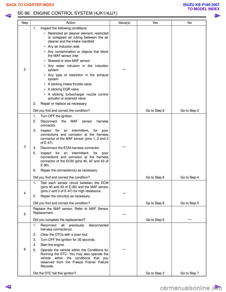
21. Inspect the following conditions:
• Restricted air cleaner element, restrictedor collapsed air tubing between the air
cleaner and the intake manifold
• Any air induction leak
• Any contamination or objects that block the MAF sensor inlet
• Skewed or slow MAF sensor
• Any water intrusion in the induction system
• Any type of restriction in the exhaust system
• A sticking intake throttle valve
• A sticking EGR valve
• A sticking turbocharger nozzle control actuator or solenoid valve
2. Repair or replace as necessary.
Did you find and correct the condition? —
Go to Step 6 Go to Step 3
3 1. Turn OFF the ignition.
2. Disconnect the MAF sensor harness connector.
3. Inspect for an intermittent, for poor connections and corrosion at the harness
connector of the MAF sensor (pins 1, 2 and 3
of E-47).
4. Disconnect the ECM harness connector.
5. Inspect for an intermittent, for poor connections and corrosion at the harness
connector of the ECM (pins 40, 42 and 43 of
E-90).
6. Repair the connection(s) as necessary.
Did you find and correct the condition? —
Go to Step 6 Go to Step 4
4 1. Test each sensor circuit between the ECM
(pins 40 and 43 of E-90) and the MAF sensor
(pins 2 and 3 of E-47) for high resistance.
2. Repair the circuit(s) as necessary.
Did you find and correct the condition? —
Go to Step 6 Go to Step 5
5 Replace the MAF sensor. Refer to MAF Sensor
Replacement.
Did you complete the replacement? —
Go to Step 6
—
61. Reconnect all previously disconnected
harness connector(s).
2. Clear the DTCs with a scan tool.
3. Turn OFF the ignition for 30 seconds.
4. Start the engine.
5. Operate the vehicle within the Conditions for Running the DTC. You may also operate the
vehicle within the conditions that you
observed from the Freeze Frame/ Failure
Records.
Did the DTC fail this ignition? —
Go to Step 2 Go to Step 7
Step Action Value(s) Yes No
BACK TO CHAPTER INDEX
TO MODEL INDEX
ISUZU KB P190 2007
Page 1715 of 6020
6E-98 ENGINE CONTROL SYSTEM (4JK1/4JJ1)
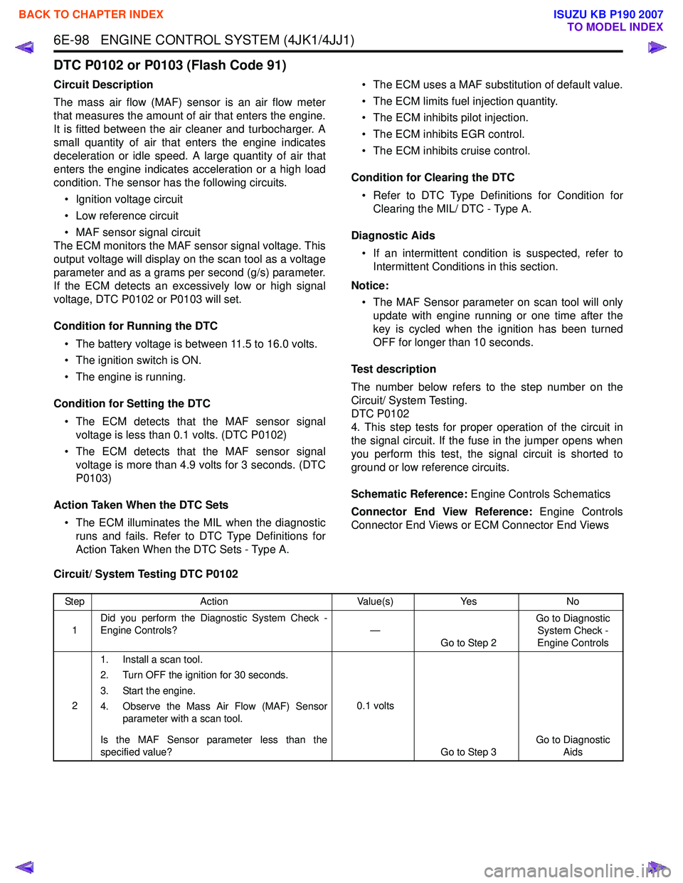
DTC P0102 or P0103 (Flash Code 91)
Circuit Description
The mass air flow (MAF) sensor is an air flow meter
that measures the amount of air that enters the engine.
It is fitted between the air cleaner and turbocharger. A
small quantity of air that enters the engine indicates
deceleration or idle speed. A large quantity of air that
enters the engine indicates acceleration or a high load
condition. The sensor has the following circuits.
• Ignition voltage circuit
• Low reference circuit
• MAF sensor signal circuit
The ECM monitors the MAF sensor signal voltage. This
output voltage will display on the scan tool as a voltage
parameter and as a grams per second (g/s) parameter.
If the ECM detects an excessively low or high signal
voltage, DTC P0102 or P0103 will set.
Condition for Running the DTC • The battery voltage is between 11.5 to 16.0 volts.
• The ignition switch is ON.
• The engine is running.
Condition for Setting the DTC • The ECM detects that the MAF sensor signal voltage is less than 0.1 volts. (DTC P0102)
• The ECM detects that the MAF sensor signal voltage is more than 4.9 volts for 3 seconds. (DTC
P0103)
Action Taken When the DTC Sets • The ECM illuminates the MIL when the diagnostic runs and fails. Refer to DTC Type Definitions for
Action Taken When the DTC Sets - Type A. • The ECM uses a MAF substitution of default value.
• The ECM limits fuel injection quantity.
• The ECM inhibits pilot injection.
• The ECM inhibits EGR control.
• The ECM inhibits cruise control.
Condition for Clearing the DTC • Refer to DTC Type Definitions for Condition for Clearing the MIL/ DTC - Type A.
Diagnostic Aids • If an intermittent condition is suspected, refer to Intermittent Conditions in this section.
Notice: • The MAF Sensor parameter on scan tool will only update with engine running or one time after the
key is cycled when the ignition has been turned
OFF for longer than 10 seconds.
Test description
The number below refers to the step number on the
Circuit/ System Testing.
DTC P0102
4. This step tests for proper operation of the circuit in
the signal circuit. If the fuse in the jumper opens when
you perform this test, the signal circuit is shorted to
ground or low reference circuits.
Schematic Reference: Engine Controls Schematics
Connector End View Reference: Engine Controls
Connector End Views or ECM Connector End Views
Circuit/ System Testing DTC P0102
Step Action Value(s)Yes No
1 Did you perform the Diagnostic System Check -
Engine Controls? —
Go to Step 2 Go to Diagnostic
System Check -
Engine Controls
2 1. Install a scan tool.
2. Turn OFF the ignition for 30 seconds.
3. Start the engine.
4. Observe the Mass Air Flow (MAF) Sensor parameter with a scan tool.
Is the MAF Sensor parameter less than the
specified value? 0.1 volts
Go to Step 3 Go to Diagnostic
Aids
BACK TO CHAPTER INDEX
TO MODEL INDEX
ISUZU KB P190 2007
Page 1719 of 6020
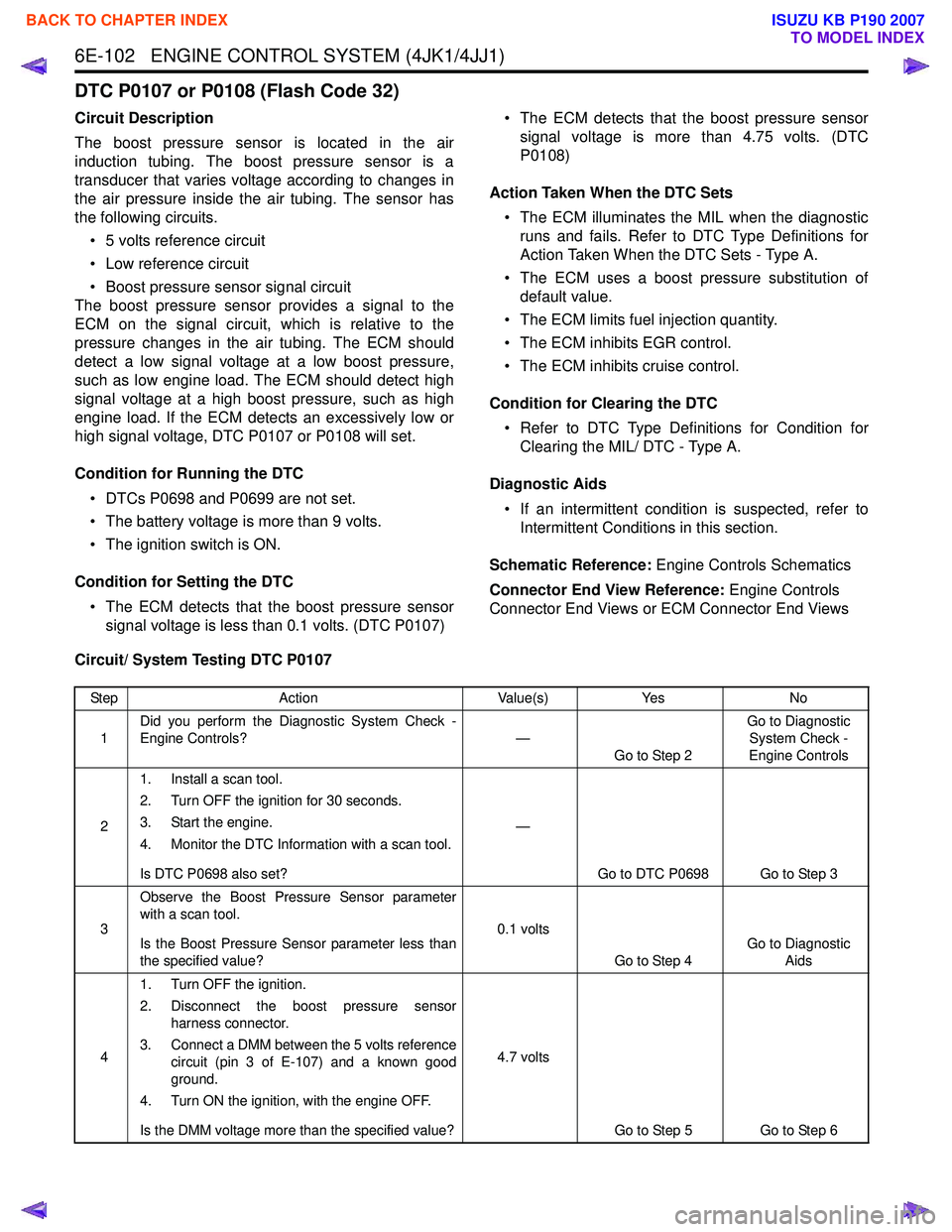
6E-102 ENGINE CONTROL SYSTEM (4JK1/4JJ1)
DTC P0107 or P0108 (Flash Code 32)
Circuit Description
The boost pressure sensor is located in the air
induction tubing. The boost pressure sensor is a
transducer that varies voltage according to changes in
the air pressure inside the air tubing. The sensor has
the following circuits.
• 5 volts reference circuit
• Low reference circuit
• Boost pressure sensor signal circuit
The boost pressure sensor provides a signal to the
ECM on the signal circuit, which is relative to the
pressure changes in the air tubing. The ECM should
detect a low signal voltage at a low boost pressure,
such as low engine load. The ECM should detect high
signal voltage at a high boost pressure, such as high
engine load. If the ECM detects an excessively low or
high signal voltage, DTC P0107 or P0108 will set.
Condition for Running the DTC • DTCs P0698 and P0699 are not set.
• The battery voltage is more than 9 volts.
• The ignition switch is ON.
Condition for Setting the DTC • The ECM detects that the boost pressure sensor signal voltage is less than 0.1 volts. (DTC P0107) • The ECM detects that the boost pressure sensor
signal voltage is more than 4.75 volts. (DTC
P0108)
Action Taken When the DTC Sets • The ECM illuminates the MIL when the diagnostic runs and fails. Refer to DTC Type Definitions for
Action Taken When the DTC Sets - Type A.
• The ECM uses a boost pressure substitution of default value.
• The ECM limits fuel injection quantity.
• The ECM inhibits EGR control.
• The ECM inhibits cruise control.
Condition for Clearing the DTC • Refer to DTC Type Definitions for Condition for Clearing the MIL/ DTC - Type A.
Diagnostic Aids • If an intermittent condition is suspected, refer to Intermittent Conditions in this section.
Schematic Reference: Engine Controls Schematics
Connector End View Reference: Engine Controls
Connector End Views or ECM Connector End Views
Circuit/ System Testing DTC P0107
Step Action Value(s)Yes No
1 Did you perform the Diagnostic System Check -
Engine Controls? —
Go to Step 2 Go to Diagnostic
System Check -
Engine Controls
2 1. Install a scan tool.
2. Turn OFF the ignition for 30 seconds.
3. Start the engine.
4. Monitor the DTC Information with a scan tool.
Is DTC P0698 also set? —
Go to DTC P0698 Go to Step 3
3 Observe the Boost Pressure Sensor parameter
with a scan tool.
Is the Boost Pressure Sensor parameter less than
the specified value? 0.1 volts
Go to Step 4 Go to Diagnostic
Aids
4 1. Turn OFF the ignition.
2. Disconnect the boost pressure sensor harness connector.
3. Connect a DMM between the 5 volts reference circuit (pin 3 of E-107) and a known good
ground.
4. Turn ON the ignition, with the engine OFF.
Is the DMM voltage more than the specified value? 4.7 volts
Go to Step 5 Go to Step 6
BACK TO CHAPTER INDEX
TO MODEL INDEX
ISUZU KB P190 2007
Page 1723 of 6020
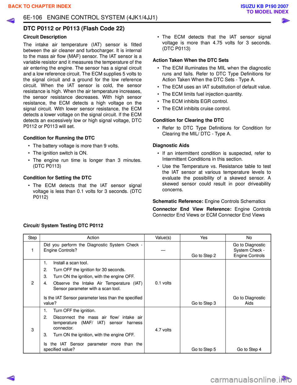
6E-106 ENGINE CONTROL SYSTEM (4JK1/4JJ1)
DTC P0112 or P0113 (Flash Code 22)
Circuit Description
The intake air temperature (IAT) sensor is fitted
between the air cleaner and turbocharger. It is internal
to the mass air flow (MAF) sensor. The IAT sensor is a
variable resistor and it measures the temperature of the
air entering the engine. The sensor has a signal circuit
and a low reference circuit. The ECM supplies 5 volts to
the signal circuit and a ground for the low reference
circuit. When the IAT sensor is cold, the sensor
resistance is high. When the air temperature increases,
the sensor resistance decreases. With high sensor
resistance, the ECM detects a high voltage on the
signal circuit. With lower sensor resistance, the ECM
detects a lower voltage on the signal circuit. If the ECM
detects an excessively low or high signal voltage, DTC
P0112 or P0113 will set.
Condition for Running the DTC • The battery voltage is more than 9 volts.
• The ignition switch is ON.
• The engine run time is longer than 3 minutes. (DTC P0113)
Condition for Setting the DTC • The ECM detects that the IAT sensor signal voltage is less than 0.1 volts for 3 seconds. (DTC
P0112) • The ECM detects that the IAT sensor signal
voltage is more than 4.75 volts for 3 seconds.
(DTC P0113)
Action Taken When the DTC Sets • The ECM illuminates the MIL when the diagnostic runs and fails. Refer to DTC Type Definitions for
Action Taken When the DTC Sets - Type A.
• The ECM uses an IAT substitution of default value.
• The ECM limits fuel injection quantity.
• The ECM inhibits EGR control.
• The ECM inhibits cruise control.
Condition for Clearing the DTC • Refer to DTC Type Definitions for Condition for Clearing the MIL/ DTC - Type A.
Diagnostic Aids • If an intermittent condition is suspected, refer to Intermittent Conditions in this section.
• Use the Temperature vs. Resistance table to test the IAT sensor at various temperature levels to
evaluate the possibility of a skewed sensor. A
skewed sensor could result in poor driveability
concerns.
Schematic Reference: Engine Controls Schematics
Connector End View Reference: Engine Controls
Connector End Views or ECM Connector End Views
Circuit/ System Testing DTC P0112
Step Action Value(s)Yes No
1 Did you perform the Diagnostic System Check -
Engine Controls? —
Go to Step 2 Go to Diagnostic
System Check -
Engine Controls
2 1. Install a scan tool.
2. Turn OFF the ignition for 30 seconds.
3. Turn ON the ignition, with the engine OFF.
4. Observe the Intake Air Temperature (IAT) Sensor parameter with a scan tool.
Is the IAT Sensor parameter less than the specified
value? 0.1 volts
Go to Step 3 Go to Diagnostic
Aids
3 1. Turn OFF the ignition.
2. Disconnect the mass air flow/ intake air temperature (MAF/ IAT) sensor harness
connector.
3. Turn ON the ignition, with the engine OFF.
Is the IAT Sensor parameter more than the
specified value? 4.7 volts
Go to Step 5 Go to Step 4
BACK TO CHAPTER INDEX
TO MODEL INDEX
ISUZU KB P190 2007
Page 1727 of 6020
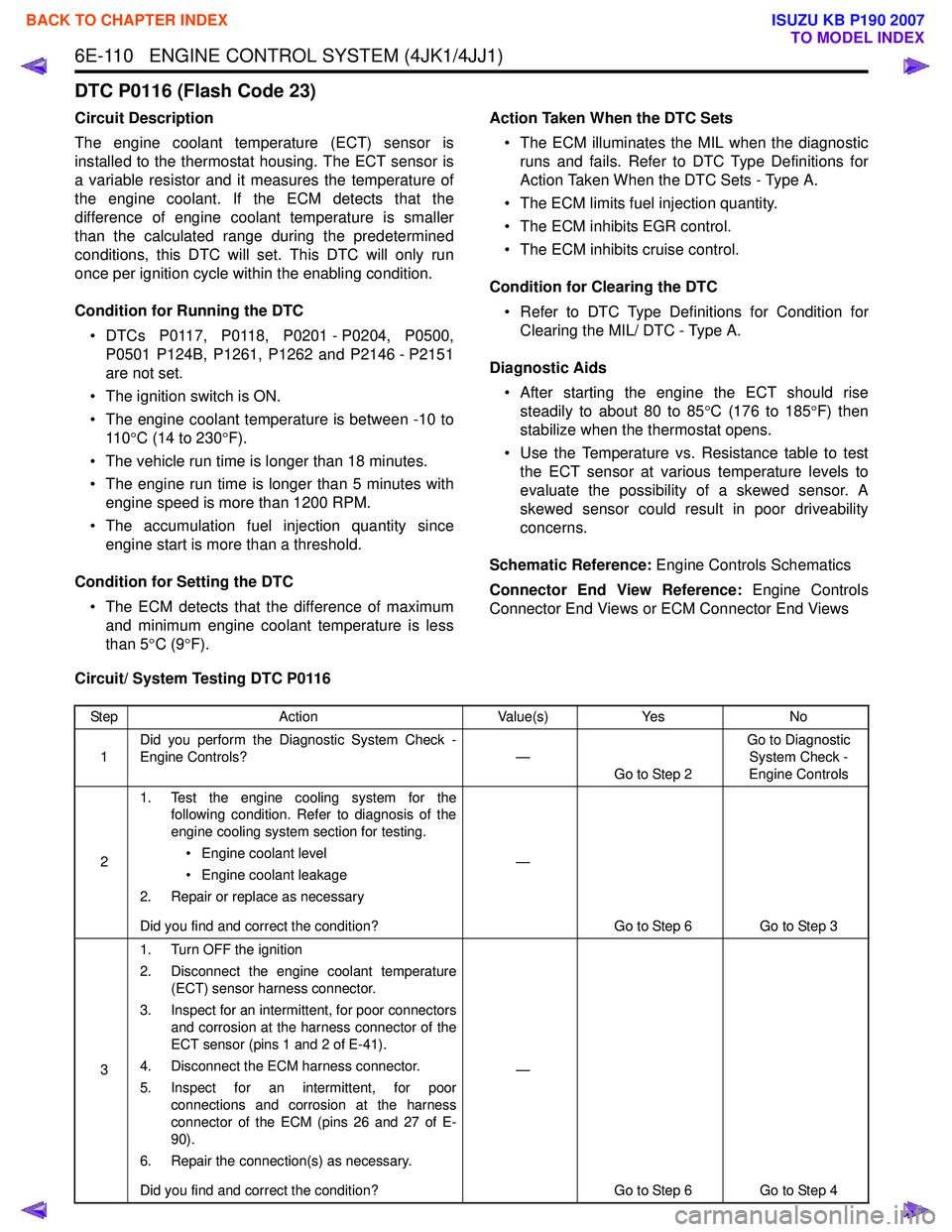
6E-110 ENGINE CONTROL SYSTEM (4JK1/4JJ1)
DTC P0116 (Flash Code 23)
Circuit Description
The engine coolant temperature (ECT) sensor is
installed to the thermostat housing. The ECT sensor is
a variable resistor and it measures the temperature of
the engine coolant. If the ECM detects that the
difference of engine coolant temperature is smaller
than the calculated range during the predetermined
conditions, this DTC will set. This DTC will only run
once per ignition cycle within the enabling condition.
Condition for Running the DTC • DTCs P0117, P0118, P0201 - P0204, P0500, P0501 P124B, P1261, P1262 and P2146 - P2151
are not set.
• The ignition switch is ON.
• The engine coolant temperature is between -10 to 11 0 °C (14 to 230 °F).
• The vehicle run time is longer than 18 minutes.
• The engine run time is longer than 5 minutes with engine speed is more than 1200 RPM.
• The accumulation fuel injection quantity since engine start is more than a threshold.
Condition for Setting the DTC • The ECM detects that the difference of maximum and minimum engine coolant temperature is less
than 5 °C (9 °F). Action Taken When the DTC Sets
• The ECM illuminates the MIL when the diagnostic runs and fails. Refer to DTC Type Definitions for
Action Taken When the DTC Sets - Type A.
• The ECM limits fuel injection quantity.
• The ECM inhibits EGR control.
• The ECM inhibits cruise control.
Condition for Clearing the DTC • Refer to DTC Type Definitions for Condition for Clearing the MIL/ DTC - Type A.
Diagnostic Aids • After starting the engine the ECT should rise steadily to about 80 to 85 °C (176 to 185 °F) then
stabilize when the thermostat opens.
• Use the Temperature vs. Resistance table to test the ECT sensor at various temperature levels to
evaluate the possibility of a skewed sensor. A
skewed sensor could result in poor driveability
concerns.
Schematic Reference: Engine Controls Schematics
Connector End View Reference: Engine Controls
Connector End Views or ECM Connector End Views
Circuit/ System Testing DTC P0116
Step Action Value(s)Yes No
1 Did you perform the Diagnostic System Check -
Engine Controls? —
Go to Step 2 Go to Diagnostic
System Check -
Engine Controls
2 1. Test the engine cooling system for the
following condition. Refer to diagnosis of the
engine cooling system section for testing.
• Engine coolant level
• Engine coolant leakage
2. Repair or replace as necessary
Did you find and correct the condition? —
Go to Step 6 Go to Step 3
3 1. Turn OFF the ignition
2. Disconnect the engine coolant temperature (ECT) sensor harness connector.
3. Inspect for an intermittent, for poor connectors and corrosion at the harness connector of the
ECT sensor (pins 1 and 2 of E-41).
4. Disconnect the ECM harness connector.
5. Inspect for an intermittent, for poor connections and corrosion at the harness
connector of the ECM (pins 26 and 27 of E-
90).
6. Repair the connection(s) as necessary.
Did you find and correct the condition? —
Go to Step 6 Go to Step 4
BACK TO CHAPTER INDEX
TO MODEL INDEX
ISUZU KB P190 2007