2007 INFINITI QX56 fuse
[x] Cancel search: fusePage 1055 of 3061
DI-44
< SERVICE INFORMATION >
WARNING CHIME
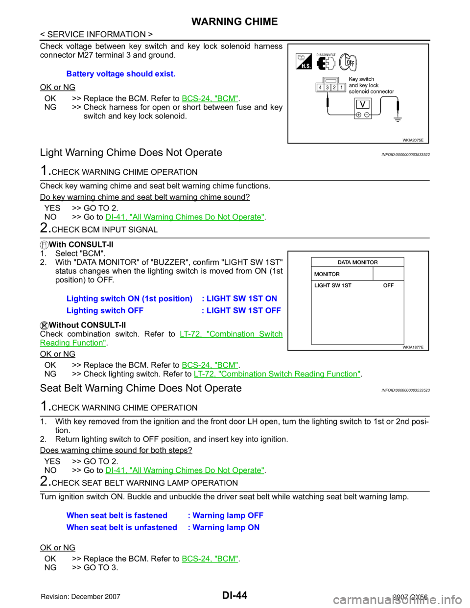
Check voltage between key switch and key lock solenoid harness
connector M27 terminal 3 and ground.
OK or NG
OK >> Replace the BCM. Refer to BCS-24, "BCM".
NG >> Check harness for open or short between fuse and key
switch and key lock solenoid.
Light Warning Chime Does Not OperateINFOID:0000000003533522
1.CHECK WARNING CHIME OPERATION
Check key warning chime and seat belt warning chime functions.
Do key warning chime and seat belt warning chime sound?
YES >> GO TO 2.
NO >> Go to DI-41, "
All Warning Chimes Do Not Operate".
2.CHECK BCM INPUT SIGNAL
With CONSULT-II
1. Select "BCM".
2. With "DATA MONITOR" of "BUZZER", confirm "LIGHT SW 1ST"
status changes when the lighting switch is moved from ON (1st
position) to OFF.
Without CONSULT-II
Check combination switch. Refer to LT-72, "
Combination Switch
Reading Function".
OK or NG
OK >> Replace the BCM. Refer to BCS-24, "BCM".
NG >> Check lighting switch. Refer to LT-72, "
Combination Switch Reading Function".
Seat Belt Warning Chime Does Not OperateINFOID:0000000003533523
1.CHECK WARNING CHIME OPERATION
1. With key removed from the ignition and the front door LH open, turn the lighting switch to 1st or 2nd posi-
tion.
2. Return lighting switch to OFF position, and insert key into ignition.
Does warning chime sound for both steps?
YES >> GO TO 2.
NO >> Go to DI-41, "
All Warning Chimes Do Not Operate".
2.CHECK SEAT BELT WARNING LAMP OPERATION
Turn ignition switch ON. Buckle and unbuckle the driver seat belt while watching seat belt warning lamp.
OK or NG
OK >> Replace the BCM. Refer to BCS-24, "BCM".
NG >> GO TO 3.Battery voltage should exist.
WKIA2075E
Lighting switch ON (1st position) : LIGHT SW 1ST ON
Lighting switch OFF : LIGHT SW 1ST OFF
WKIA1877E
When seat belt is fastened : Warning lamp OFF
When seat belt is unfastened : Warning lamp ON
Page 1057 of 3061
DI-46
< SERVICE INFORMATION >
REAR SONAR SYSTEM
REAR SONAR SYSTEM
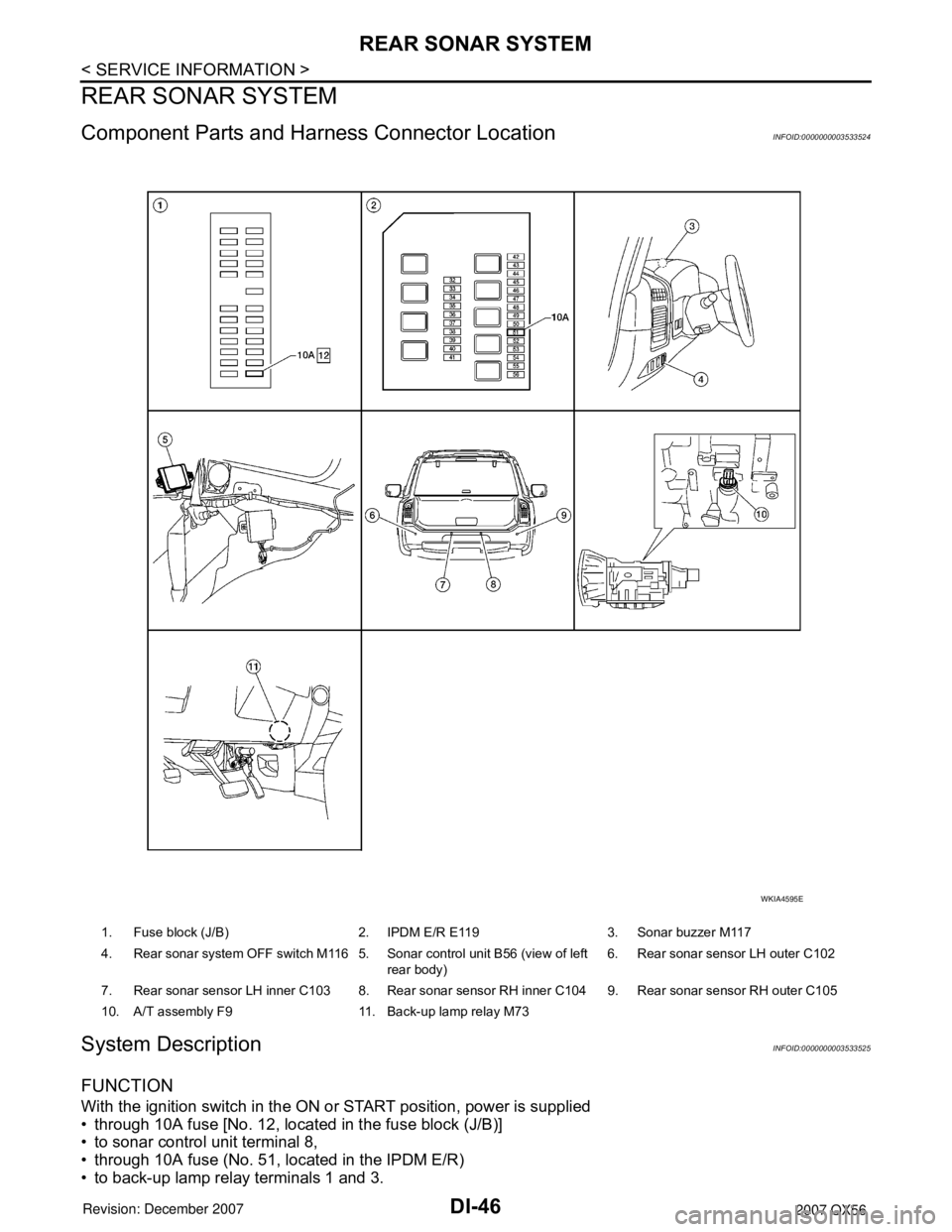
Component Parts and Harness Connector LocationINFOID:0000000003533524
System DescriptionINFOID:0000000003533525
FUNCTION
With the ignition switch in the ON or START position, power is supplied
• through 10A fuse [No. 12, located in the fuse block (J/B)]
• to sonar control unit terminal 8,
• through 10A fuse (No. 51, located in the IPDM E/R)
• to back-up lamp relay terminals 1 and 3.
1. Fuse block (J/B) 2. IPDM E/R E119 3. Sonar buzzer M117
4. Rear sonar system OFF switch M116 5. Sonar control unit B56 (view of left
rear body)6. Rear sonar sensor LH outer C102
7. Rear sonar sensor LH inner C103 8. Rear sonar sensor RH inner C104 9. Rear sonar sensor RH outer C105
10. A/T assembly F9 11. Back-up lamp relay M73
WKIA4595E
Page 1064 of 3061
REAR SONAR SYSTEM
DI-53
< SERVICE INFORMATION >
C
D
E
F
G
H
I
J
L
MA
B
DI
N
O
P
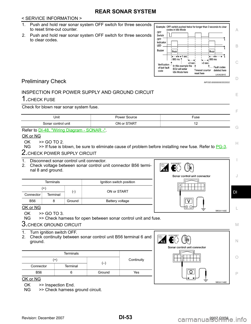
1. Push and hold rear sonar system OFF switch for three seconds
to reset time-out counter.
2. Push and hold rear sonar system OFF switch for three seconds
to clear codes.
Preliminary CheckINFOID:0000000003533532
INSPECTION FOR POWER SUPPLY AND GROUND CIRCUIT
1.CHECK FUSE
Check for blown rear sonar system fuse.
Refer to DI-48, "
Wiring Diagram - SONAR -".
OK or NG
OK >> GO TO 2.
NG >> If fuse is blown, be sure to eliminate cause of problem before installing new fuse. Refer to PG-3
.
2.CHECK POWER SUPPLY CIRCUIT
1. Disconnect sonar control unit connector.
2. Check voltage between sonar control unit connector B56 termi-
nal 8 and ground.
OK or NG
OK >> GO TO 3.
NG >> Check harness for open between sonar control unit and fuse.
3.CHECK GROUND CIRCUIT
1. Turn ignition switch OFF.
2. Check continuity between sonar control unit B56 terminal 6 and
ground.
OK or NG
OK >> Inspection End.
NG >> Check harness ground circuit.
LKIA0391E
Unit Power Source Fuse
Sonar control unit ON or START 12
Terminals Ignition switch position
(+)
(-) ON or START
Connector Terminal
B56 8 Ground Battery voltage
WKIA1145E
Te r m i n a l s
Continuity (+)
(–)
Connector Terminal
B56 6 Ground Yes
WKIA1146E
Page 1069 of 3061
DI-58
< SERVICE INFORMATION >
REAR VIEW MONITOR
REAR VIEW MONITOR
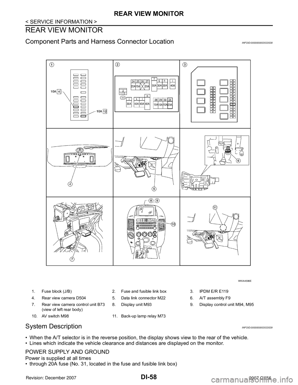
Component Parts and Harness Connector LocationINFOID:0000000003533538
System DescriptionINFOID:0000000003533539
• When the A/T selector is in the reverse position, the display shows view to the rear of the vehicle.
• Lines which indicate the vehicle clearance and distances are displayed on the monitor.
POWER SUPPLY AND GROUND
Power is supplied at all times
• through 20A fuse (No. 31, located in the fuse and fusible link box)
1. Fuse block (J/B) 2. Fuse and fusible link box 3. IPDM E/R E119
4. Rear view camera D504 5. Data link connector M22 6. A/T assembly F9
7. Rear view camera control unit B73
(view of left rear body)8. Display unit M93 9. Display control unit M94, M95
10. AV switch M98 11. Back-up lamp relay M73
WKIA4596E
Page 1070 of 3061
REAR VIEW MONITOR
DI-59
< SERVICE INFORMATION >
C
D
E
F
G
H
I
J
L
MA
B
DI
N
O
P
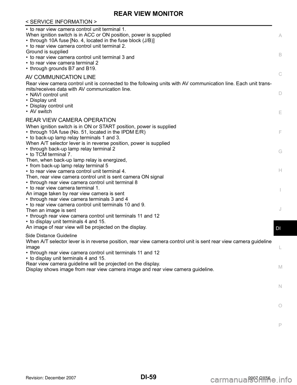
• to rear view camera control unit terminal 1.
When ignition switch is in ACC or ON position, power is supplied
• through 10A fuse [No. 4, located in the fuse block (J/B)]
• to rear view camera control unit terminal 2.
Ground is supplied
• to rear view camera control unit terminal 3 and
• to rear view camera terminal 2
• through grounds B7 and B19.
AV COMMUNICATION LINE
Rear view camera control unit is connected to the following units with AV communication line. Each unit trans-
mits/receives data with AV communication line.
• NAVI control unit
• Display unit
• Display control unit
• AV switch
REAR VIEW CAMERA OPERATION
When ignition switch is in ON or START position, power is supplied
• through 10A fuse (No. 51, located in the IPDM E/R)
• to back-up lamp relay terminals 1 and 3.
When A/T selector lever is in reverse position, power is supplied
• through back-up lamp relay terminal 2
• to TCM terminal 7.
Then, when back-up lamp relay is energized,
• from back-up lamp relay terminal 5
• to rear view camera control unit terminal 4.
Then, rear view camera control unit is sent camera ON signal
• through rear view camera control unit terminal 8
• to rear view camera terminal 1.
An image taken by rear view camera is sent
• through rear view camera terminals 3 and 4
• to rear view camera control unit terminals 10 and 9.
Then an image is sent
• through rear view camera control unit terminals 11 and 12
• to display unit terminals 4 and 15.
An image of rear view will be projected on the display.
Side Distance Guideline
When A/T selector lever is in reverse position, rear view camera control unit is sent rear view camera guideline
image
• through rear view camera control unit terminals 11 and 12
• to display unit terminals 4 and 15.
Rear view camera guideline will be projected on the display.
Display shows image from rear view camera image and rear view camera guideline.
Page 1078 of 3061
REAR VIEW MONITOR
DI-67
< SERVICE INFORMATION >
C
D
E
F
G
H
I
J
L
MA
B
DI
N
O
P
Power Supply and Ground Circuit InspectionINFOID:0000000003533546
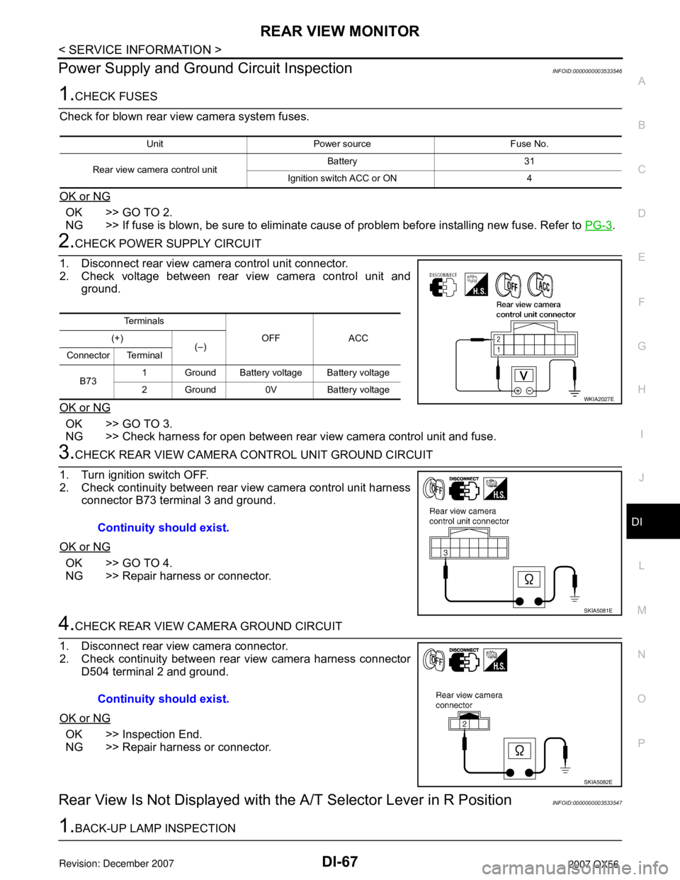
1.CHECK FUSES
Check for blown rear view camera system fuses.
OK or NG
OK >> GO TO 2.
NG >> If fuse is blown, be sure to eliminate cause of problem before installing new fuse. Refer to PG-3
.
2.CHECK POWER SUPPLY CIRCUIT
1. Disconnect rear view camera control unit connector.
2. Check voltage between rear view camera control unit and
ground.
OK or NG
OK >> GO TO 3.
NG >> Check harness for open between rear view camera control unit and fuse.
3.CHECK REAR VIEW CAMERA CONTROL UNIT GROUND CIRCUIT
1. Turn ignition switch OFF.
2. Check continuity between rear view camera control unit harness
connector B73 terminal 3 and ground.
OK or NG
OK >> GO TO 4.
NG >> Repair harness or connector.
4.CHECK REAR VIEW CAMERA GROUND CIRCUIT
1. Disconnect rear view camera connector.
2. Check continuity between rear view camera harness connector
D504 terminal 2 and ground.
OK or NG
OK >> Inspection End.
NG >> Repair harness or connector.
Rear View Is Not Displayed with the A/T Selector Lever in R PositionINFOID:0000000003533547
1.BACK-UP LAMP INSPECTION
Unit Power source Fuse No.
Rear view camera control unitBattery 31
Ignition switch ACC or ON 4
Te r m i n a l s
OFF ACC (+)
(–)
Connector Terminal
B731 Ground Battery voltage Battery voltage
2 Ground 0V Battery voltage
WKIA2027E
Continuity should exist.
SKIA5081E
Continuity should exist.
SKIA5082E
Page 1163 of 3061
EC-80
< SERVICE INFORMATION >
BASIC SERVICE PROCEDURE
3.Check that downstream of throttle valve is free from air leakage.
4.When the above three items check out OK, engine component parts and their installation condi-
tion are questionable. Check and eliminate the cause of the incident.
It is useful to perform EC-129
.
5.If any of the following conditions occur after the engine has started, eliminate the cause of the
incident and perform Idle Air Volume Learning all over again:
•Engine stalls.
•Erroneous idle.
Fuel Pressure CheckINFOID:0000000003531616
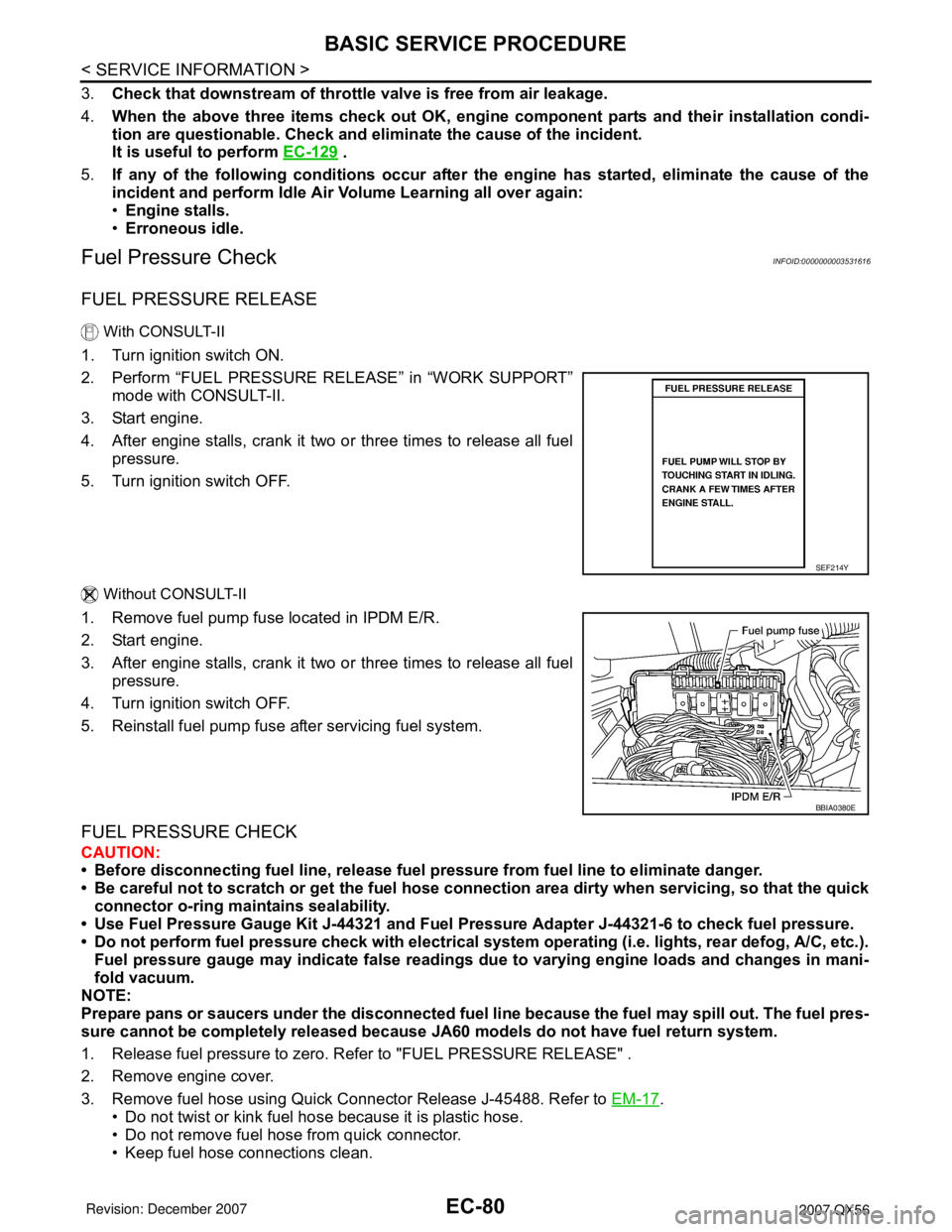
FUEL PRESSURE RELEASE
With CONSULT-II
1. Turn ignition switch ON.
2. Perform “FUEL PRESSURE RELEASE” in “WORK SUPPORT”
mode with CONSULT-II.
3. Start engine.
4. After engine stalls, crank it two or three times to release all fuel
pressure.
5. Turn ignition switch OFF.
Without CONSULT-II
1. Remove fuel pump fuse located in IPDM E/R.
2. Start engine.
3. After engine stalls, crank it two or three times to release all fuel
pressure.
4. Turn ignition switch OFF.
5. Reinstall fuel pump fuse after servicing fuel system.
FUEL PRESSURE CHECK
CAUTION:
• Before disconnecting fuel line, release fuel pressure from fuel line to eliminate danger.
• Be careful not to scratch or get the fuel hose connection area dirty when servicing, so that the quick
connector o-ring maintains sealability.
• Use Fuel Pressure Gauge Kit J-44321 and Fuel Pressure Adapter J-44321-6 to check fuel pressure.
• Do not perform fuel pressure check with electrical system operating (i.e. lights, rear defog, A/C, etc.).
Fuel pressure gauge may indicate false readings due to varying engine loads and changes in mani-
fold vacuum.
NOTE:
Prepare pans or saucers under the disconnected fuel line because the fuel may spill out. The fuel pres-
sure cannot be completely released because JA60 models do not have fuel return system.
1. Release fuel pressure to zero. Refer to "FUEL PRESSURE RELEASE" .
2. Remove engine cover.
3. Remove fuel hose using Quick Connector Release J-45488. Refer to EM-17
.
• Do not twist or kink fuel hose because it is plastic hose.
• Do not remove fuel hose from quick connector.
• Keep fuel hose connections clean.
SEF214Y
BBIA0380E
Page 1223 of 3061
EC-140
< SERVICE INFORMATION >
POWER SUPPLY AND GROUND CIRCUIT
Diagnosis Procedure
INFOID:0000000003531637
1.INSPECTION START
Start engine.
Is engine running?
Ye s o r N o
Ye s > > G O T O 8 .
No >> GO TO 2.
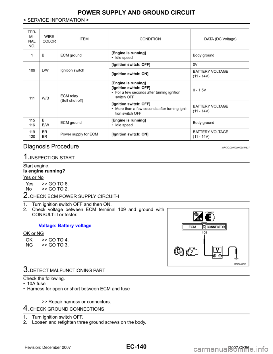
2.CHECK ECM POWER SUPPLY CIRCUIT-I
1. Turn ignition switch OFF and then ON.
2. Check voltage between ECM terminal 109 and ground with
CONSULT-II or tester.
OK or NG
OK >> GO TO 4.
NG >> GO TO 3.
3.DETECT MALFUNCTIONING PART
Check the following.
• 10A fuse
• Harness for open or short between ECM and fuse
>> Repair harness or connectors.
4.CHECK GROUND CONNECTIONS
1. Turn ignition switch OFF.
2. Loosen and retighten three ground screws on the body.
TER-
MI-
NAL
NO.WIRE
COLORITEM CONDITION DATA (DC Voltage)
1 B ECM ground[Engine is running]
• Idle speedBody ground
109 L/W Ignition switch[Ignition switch: OFF]0V
[Ignition switch: ON]BATTERY VOLTAGE
(11 - 14V)
111 W / BECM relay
(Self shut-off)[Engine is running]
[Ignition switch: OFF]
• For a few seconds after turning ignition
switch OFF0 - 1.5V
[Ignition switch: OFF]
• More than a few seconds after turning igni-
tion switch OFFBATTERY VOLTAGE
(11 - 14V)
11 5
11 6B
B/WECM ground[Engine is running]
• Idle speedBody ground
11 9
120BR
BRPower supply for ECM[Ignition switch: ON]BATTERY VOLTAGE
(11 - 14V)
Voltage: Battery voltage
MBIB0015E