2007 INFINITI QX56 fuse
[x] Cancel search: fusePage 1699 of 3061
EC-616
< SERVICE INFORMATION >
FUEL PUMP
>> Repair harness or connectors.
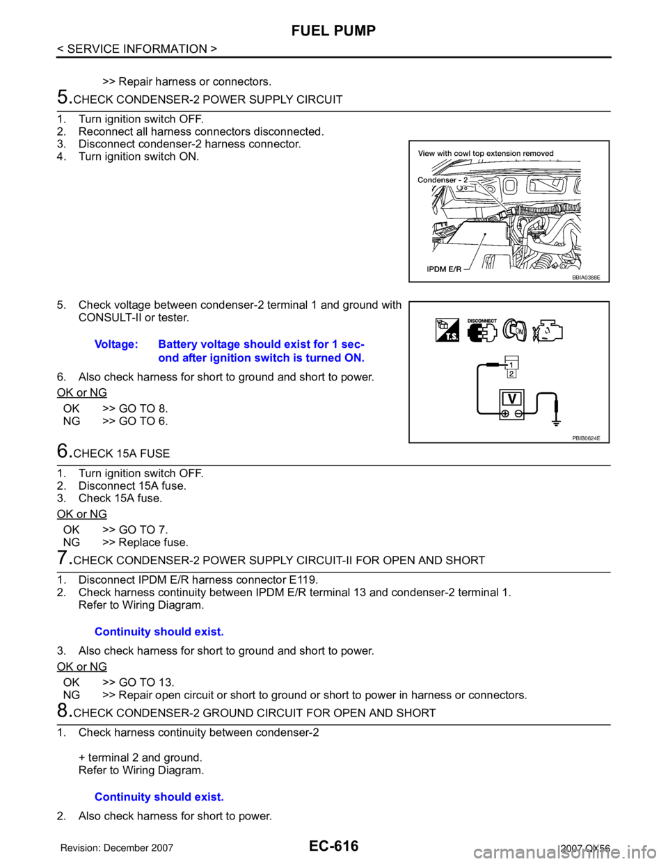
5.CHECK CONDENSER-2 POWER SUPPLY CIRCUIT
1. Turn ignition switch OFF.
2. Reconnect all harness connectors disconnected.
3. Disconnect condenser-2 harness connector.
4. Turn ignition switch ON.
5. Check voltage between condenser-2 terminal 1 and ground with
CONSULT-II or tester.
6. Also check harness for short to ground and short to power.
OK or NG
OK >> GO TO 8.
NG >> GO TO 6.
6.CHECK 15A FUSE
1. Turn ignition switch OFF.
2. Disconnect 15A fuse.
3. Check 15A fuse.
OK or NG
OK >> GO TO 7.
NG >> Replace fuse.
7.CHECK CONDENSER-2 POWER SUPPLY CIRCUIT-II FOR OPEN AND SHORT
1. Disconnect IPDM E/R harness connector E119.
2. Check harness continuity between IPDM E/R terminal 13 and condenser-2 terminal 1.
Refer to Wiring Diagram.
3. Also check harness for short to ground and short to power.
OK or NG
OK >> GO TO 13.
NG >> Repair open circuit or short to ground or short to power in harness or connectors.
8.CHECK CONDENSER-2 GROUND CIRCUIT FOR OPEN AND SHORT
1. Check harness continuity between condenser-2
+ terminal 2 and ground.
Refer to Wiring Diagram.
2. Also check harness for short to power.
BBIA0388E
Voltage: Battery voltage should exist for 1 sec-
ond after ignition switch is turned ON.
PBIB0624E
Continuity should exist.
Continuity should exist.
Page 1705 of 3061
EC-622
< SERVICE INFORMATION >
ICC BRAKE SWITCH
Without CONSULT-II
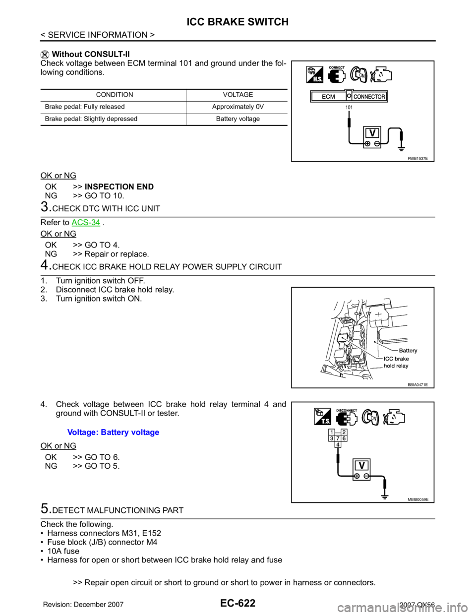
Check voltage between ECM terminal 101 and ground under the fol-
lowing conditions.
OK or NG
OK >>INSPECTION END
NG >> GO TO 10.
3.CHECK DTC WITH ICC UNIT
Refer to ACS-34
.
OK or NG
OK >> GO TO 4.
NG >> Repair or replace.
4.CHECK ICC BRAKE HOLD RELAY POWER SUPPLY CIRCUIT
1. Turn ignition switch OFF.
2. Disconnect ICC brake hold relay.
3. Turn ignition switch ON.
4. Check voltage between ICC brake hold relay terminal 4 and
ground with CONSULT-II or tester.
OK or NG
OK >> GO TO 6.
NG >> GO TO 5.
5.DETECT MALFUNCTIONING PART
Check the following.
• Harness connectors M31, E152
• Fuse block (J/B) connector M4
• 10A fuse
• Harness for open or short between ICC brake hold relay and fuse
>> Repair open circuit or short to ground or short to power in harness or connectors.
CONDITION VOLTAGE
Brake pedal: Fully released Approximately 0V
Brake pedal: Slightly depressed Battery voltage
PBIB1537E
BBIA0471E
Voltage: Battery voltage
MBIB0059E
Page 1707 of 3061
EC-624
< SERVICE INFORMATION >
ICC BRAKE SWITCH
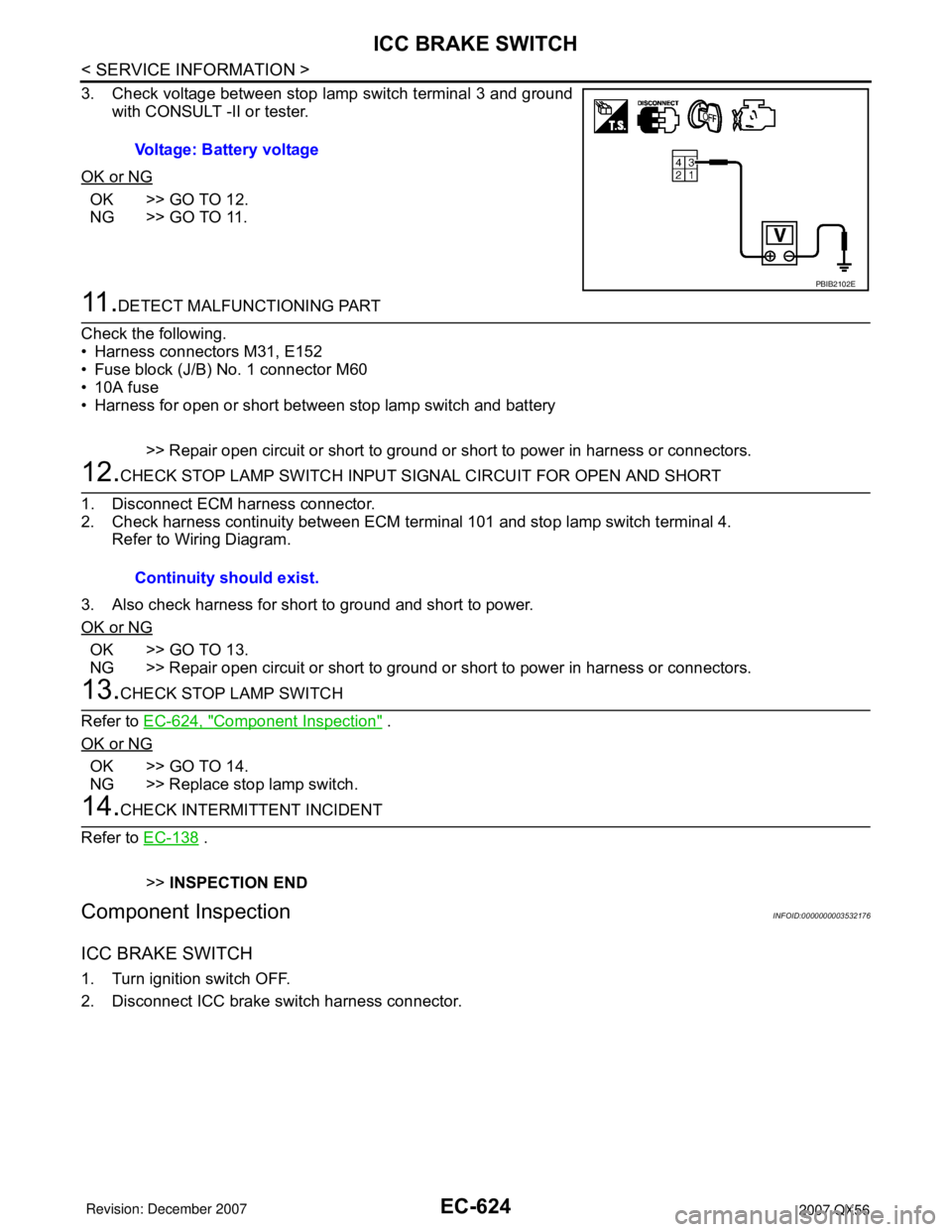
3. Check voltage between stop lamp switch terminal 3 and ground
with CONSULT -II or tester.
OK or NG
OK >> GO TO 12.
NG >> GO TO 11.
11 .DETECT MALFUNCTIONING PART
Check the following.
• Harness connectors M31, E152
• Fuse block (J/B) No. 1 connector M60
• 10A fuse
• Harness for open or short between stop lamp switch and battery
>> Repair open circuit or short to ground or short to power in harness or connectors.
12.CHECK STOP LAMP SWITCH INPUT SIGNAL CIRCUIT FOR OPEN AND SHORT
1. Disconnect ECM harness connector.
2. Check harness continuity between ECM terminal 101 and stop lamp switch terminal 4.
Refer to Wiring Diagram.
3. Also check harness for short to ground and short to power.
OK or NG
OK >> GO TO 13.
NG >> Repair open circuit or short to ground or short to power in harness or connectors.
13.CHECK STOP LAMP SWITCH
Refer to EC-624, "
Component Inspection" .
OK or NG
OK >> GO TO 14.
NG >> Replace stop lamp switch.
14.CHECK INTERMITTENT INCIDENT
Refer to EC-138
.
>>INSPECTION END
Component InspectionINFOID:0000000003532176
ICC BRAKE SWITCH
1. Turn ignition switch OFF.
2. Disconnect ICC brake switch harness connector.Voltage: Battery voltage
PBIB2102E
Continuity should exist.
Page 1719 of 3061
EC-636
< SERVICE INFORMATION >
IGNITION SIGNAL
Do the following procedure in the place where ventilation is good without the combustible.
1. Turn ignition switch OFF.
2. Disconnect ignition coil harness connector.
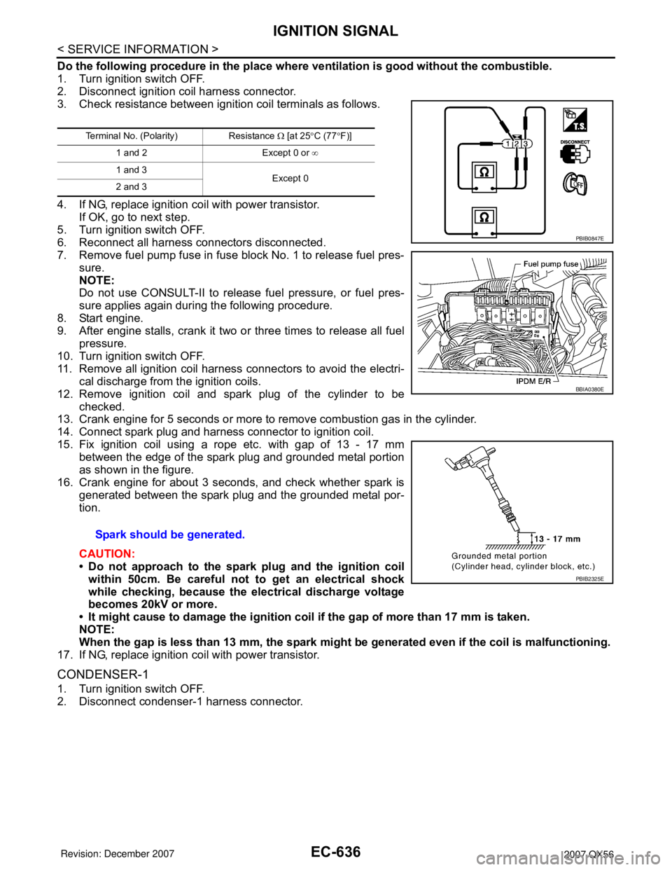
3. Check resistance between ignition coil terminals as follows.
4. If NG, replace ignition coil with power transistor.
If OK, go to next step.
5. Turn ignition switch OFF.
6. Reconnect all harness connectors disconnected.
7. Remove fuel pump fuse in fuse block No. 1 to release fuel pres-
sure.
NOTE:
Do not use CONSULT-II to release fuel pressure, or fuel pres-
sure applies again during the following procedure.
8. Start engine.
9. After engine stalls, crank it two or three times to release all fuel
pressure.
10. Turn ignition switch OFF.
11. Remove all ignition coil harness connectors to avoid the electri-
cal discharge from the ignition coils.
12. Remove ignition coil and spark plug of the cylinder to be
checked.
13. Crank engine for 5 seconds or more to remove combustion gas in the cylinder.
14. Connect spark plug and harness connector to ignition coil.
15. Fix ignition coil using a rope etc. with gap of 13 - 17 mm
between the edge of the spark plug and grounded metal portion
as shown in the figure.
16. Crank engine for about 3 seconds, and check whether spark is
generated between the spark plug and the grounded metal por-
tion.
CAUTION:
• Do not approach to the spark plug and the ignition coil
within 50cm. Be careful not to get an electrical shock
while checking, because the electrical discharge voltage
becomes 20kV or more.
• It might cause to damage the ignition coil if the gap of more than 17 mm is taken.
NOTE:
When the gap is less than 13 mm, the spark might be generated even if the coil is malfunctioning.
17. If NG, replace ignition coil with power transistor.
CONDENSER-1
1. Turn ignition switch OFF.
2. Disconnect condenser-1 harness connector.
Terminal No. (Polarity) Resistance Ω [at 25°C (77°F)]
1 and 2 Except 0 or ∞
1 and 3
Except 0
2 and 3
Spark should be generated.
PBIB0847E
BBIA0380E
PBIB2325E
Page 1834 of 3061
EM-64
< SERVICE INFORMATION >
CYLINDER HEAD
CYLINDER HEAD
On-Vehicle ServiceINFOID:0000000003531540
CHECKING COMPRESSION PRESSURE
1. Warm up the engine thoroughly. Then stop the engine.
2. Release the fuel pressure. Refer to EC-80, "
Fuel Pressure Check".
CAUTION:
If CONSULT-II is not used to release fuel pressure leave the fu el pump fuse disconnected until
step 7.
3. Remove the spark plug from each cylinder. Refer to EM-29, "
Removal and Installation".
4. Connect the engine tachometer (not required in use of CONSULT-II).
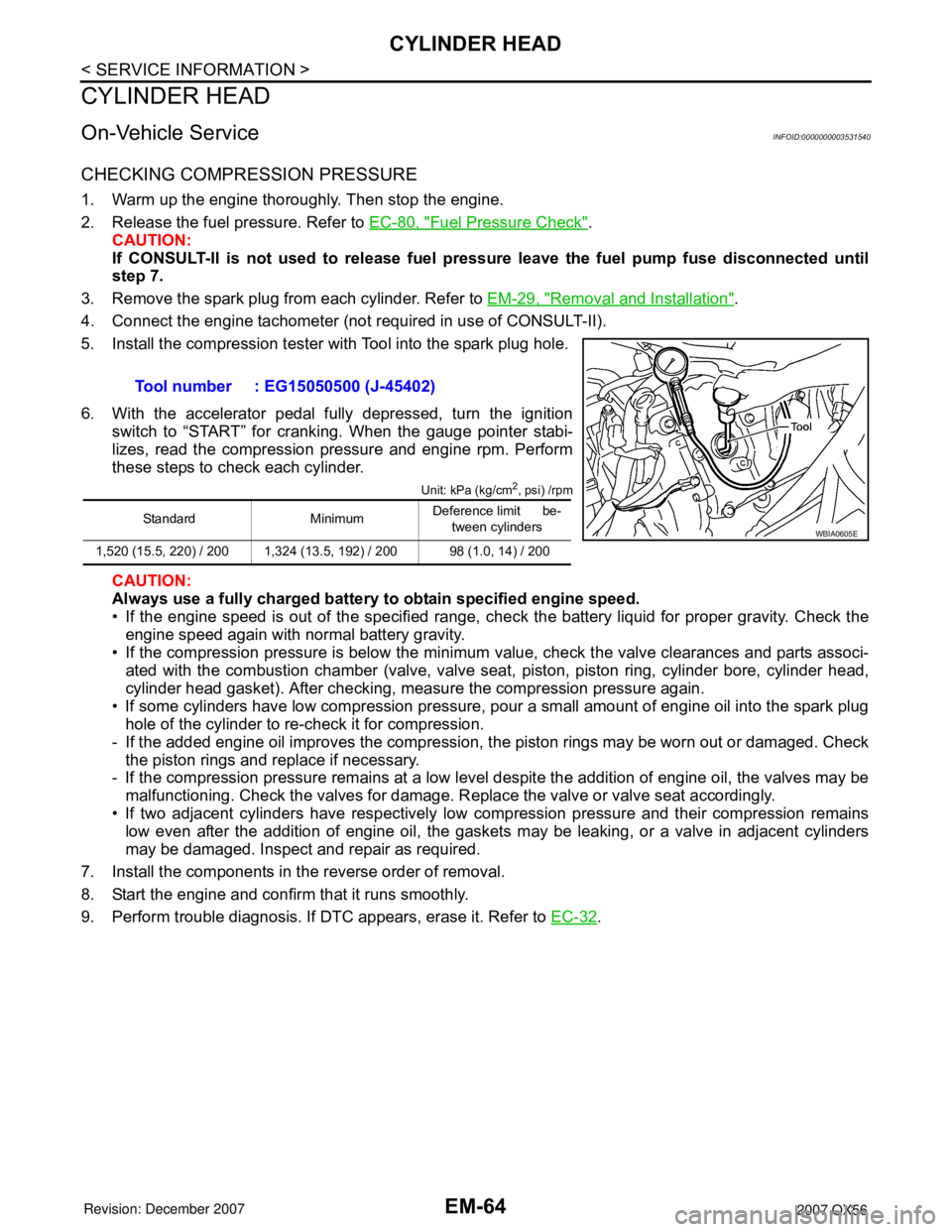
5. Install the compression tester with Tool into the spark plug hole.
6. With the accelerator pedal fully depressed, turn the ignition switch to “START” for cranking. When the gauge pointer stabi-
lizes, read the compression pressure and engine rpm. Perform
these steps to check each cylinder.
Unit: kPa (kg/cm2, psi) /rpm
CAUTION:
Always use a fully charged battery to obtain specified engine speed.
• If the engine speed is out of the specified range, che ck the battery liquid for proper gravity. Check the
engine speed again with normal battery gravity.
• If the compression pressure is below the minimum value, check the valve clearances and parts associ- ated with the combustion chamber (valve, valve seat , piston, piston ring, cylinder bore, cylinder head,
cylinder head gasket). After checking, measure the compression pressure again.
• If some cylinders have low compression pressure, pour a small amount of engine oil into the spark plug hole of the cylinder to re-check it for compression.
- If the added engine oil improves the compression, t he piston rings may be worn out or damaged. Check
the piston rings and replace if necessary.
- If the compression pressure remains at a low level despite the addition of engine oil, the valves may be
malfunctioning. Check the valves for damage. R eplace the valve or valve seat accordingly.
• If two adjacent cylinders have respectively low co mpression pressure and their compression remains
low even after the addition of engine oil, the gaskets may be leaking, or a valve in adjacent cylinders
may be damaged. Inspect and repair as required.
7. Install the components in the reverse order of removal.
8. Start the engine and confirm that it runs smoothly.
9. Perform trouble diagnosis. If DTC appears, erase it. Refer to EC-32
.
Tool number : EG15050500 (J-45402)
Standard Minimum
Deference limit be-
tween cylinders
1,520 (15.5, 220) / 200 1,324 (13.5, 192) / 200 98 (1.0, 14) / 200WBIA0605E
Page 1845 of 3061
ENGINE ASSEMBLY
EM-75
< SERVICE INFORMATION >
C
D
E
F
G
H
I
J
K
L
MA
EM
N
P O
6. Remove the engine room cover using power tools.
7. Remove the air duct and air cleaner case assembly. Refer to EM-15, "
Removal and Installation".
8. Disconnect the vacuum hose between the vehicle and engine and set it aside.
9. Remove the radiator assembly and hoses. Refer to CO-13, "
Removal and Installation".
10. Remove the drive belts. Refer to EM-15, "
Removal and Installation".
11. Remove the fan blade. Refer to CO-16, "
Removal and Installation (Crankshaft Driven Type)".
12. Disconnect the engine room harness from the fuse box and set it aside.
13. Disconnect the ECM.
14. Disconnect the engine room harness from the engine side and set it aside.
15. Disconnect the engine harness grounds.
16. Disconnect the power steering reservoir tank from the engine and move it aside.
17. Disconnect the power steering oil pump from the engine. Move it aside and secure it using suitable wire or
rope. Refer to PS-21, "
Removal and Installation".
18. Remove the A/C compressor bolts and set the compressor aside. Refer to ATC-154, "
Removal and Instal-
lation for Compressor" (ATC).
19. Disconnect the brake booster vacuum line.
20. Disconnect the EVAP line.
21. Disconnect the fuel hose at the engine side connection. Refer to EM-31, "
Removal and Installation".
22. Disconnect the heater hoses at the cowl, and install plugs to avoid leakage of engine coolant.
23. Remove the A/T oil level indicator and indicator tube upper bolts.
24. Remove the front final drive assembly (4WD only). Refer to FFD-12, "
Removal and Installation".
25. Remove the exhaust manifolds. Refer to EM-21, "
Removal and Installation".
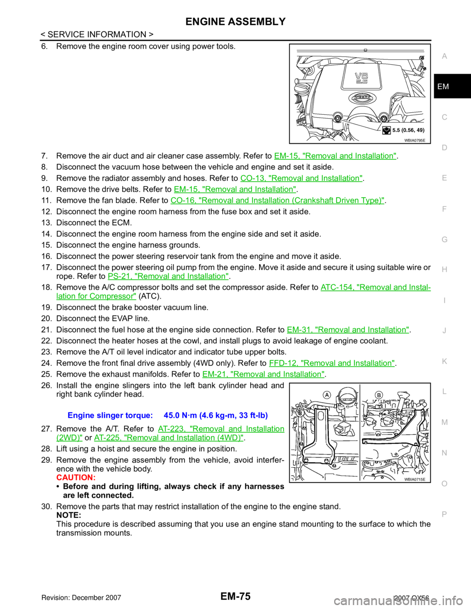
26. Install the engine slingers into the left bank cylinder head and
right bank cylinder head.
27. Remove the A/T. Refer to AT-223, "
Removal and Installation
(2WD)" or AT-225, "Removal and Installation (4WD)".
28. Lift using a hoist and secure the engine in position.
29. Remove the engine assembly from the vehicle, avoid interfer-
ence with the vehicle body.
CAUTION:
• Before and during lifting, always check if any harnesses
are left connected.
30. Remove the parts that may restrict installation of the engine to the engine stand.
NOTE:
This procedure is described assuming that you use an engine stand mounting to the surface to which the
transmission mounts.
WBIA0795E
Engine slinger torque: 45.0 N·m (4.6 kg-m, 33 ft-lb)
WBIA0715E
Page 1860 of 3061
EM-90
< SERVICE INFORMATION >
CYLINDER BLOCK
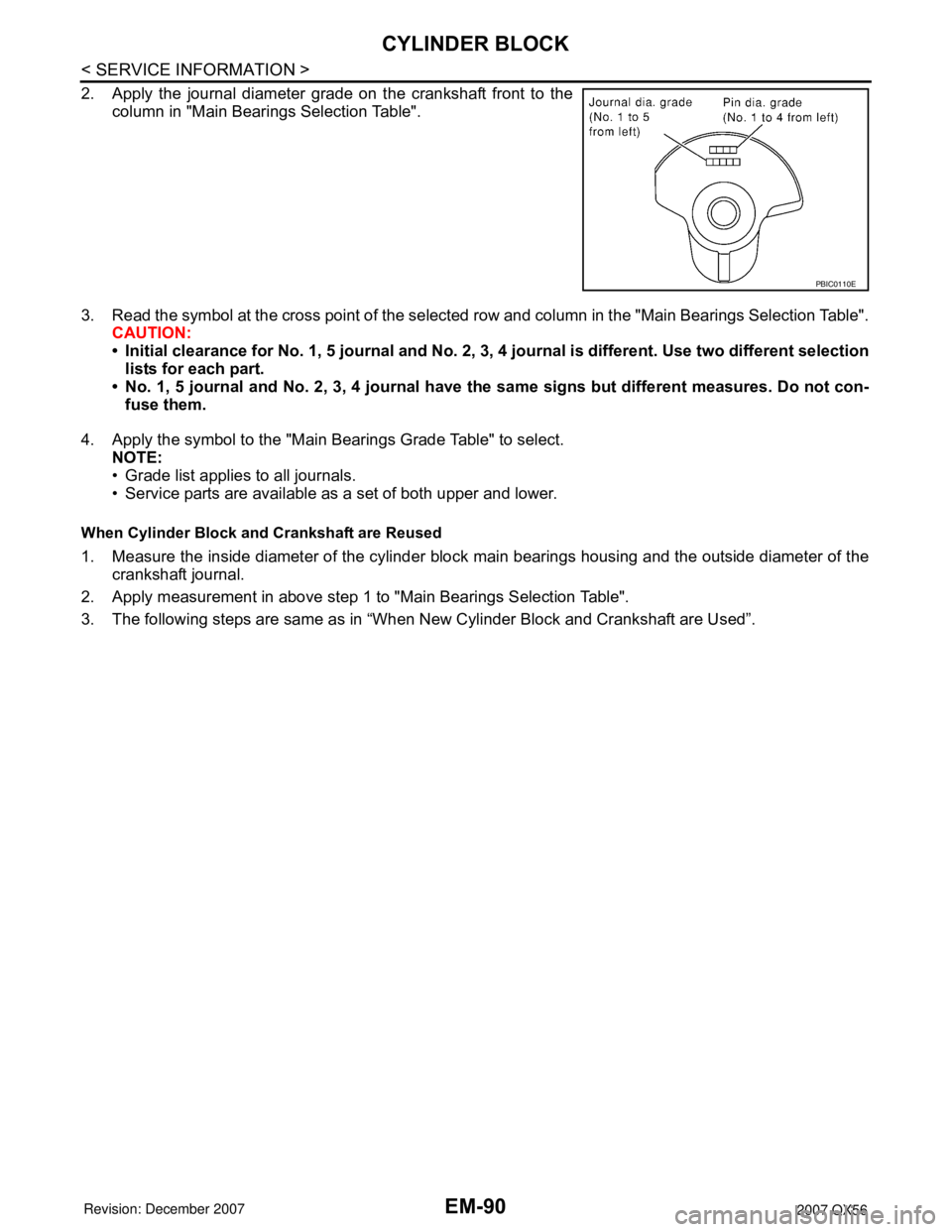
2. Apply the journal diameter grade on the crankshaft front to the
column in "Main Bearings Selection Table".
3. Read the symbol at the cross point of the selected row and column in the "Main Bearings Selection Table".
CAUTION:
• Initial clearance for No. 1, 5 journal and No. 2, 3, 4 journal is different. Use two different selection
lists for each part.
• No. 1, 5 journal and No. 2, 3, 4 journal have the same signs but different measures. Do not con-
fuse them.
4. Apply the symbol to the "Main Bearings Grade Table" to select.
NOTE:
• Grade list applies to all journals.
• Service parts are available as a set of both upper and lower.
When Cylinder Block and Crankshaft are Reused
1. Measure the inside diameter of the cylinder block main bearings housing and the outside diameter of the
crankshaft journal.
2. Apply measurement in above step 1 to "Main Bearings Selection Table".
3. The following steps are same as in “When New Cylinder Block and Crankshaft are Used”.
PBIC0110E
Page 1982 of 3061
GI-16
< SERVICE INFORMATION >
HOW TO USE THIS MANUAL
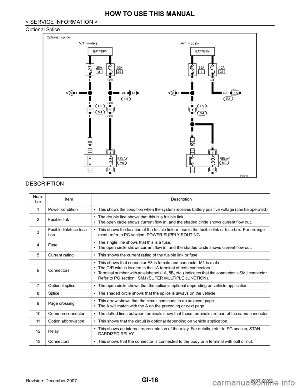
Optional Splice
DESCRIPTION
SGI942
Num-
berItem Description
1 Power condition • This shows the condition when the system receives battery positive voltage (can be operated).
2 Fusible link• The double line shows that this is a fusible link.
• The open circle shows current flow in, and the shaded circle shows current flow out.
3Fusible link/fuse loca-
tion• This shows the location of the fusible link or fuse in the fusible link or fuse box. For arrange-
ment, refer to PG section, POWER SUPPLY ROUTING.
4Fuse• The single line shows that this is a fuse.
• The open circle shows current flow in, and the shaded circle shows current flow out.
5 Current rating • This shows the current rating of the fusible link or fuse.
6 Connectors• This shows that connector E3 is female and connector M1 is male.
• The G/R wire is located in the 1A terminal of both connectors.
• Terminal number with an alphabet (1A, 5B, etc.) indicates that the connector is SMJ connector.
Refer to PG section, SMJ (SUPER MULTIPLE JUNCTION).
7 Optional splice • The open circle shows that the splice is optional depending on vehicle application.
8 Splice • The shaded circle shows that the splice is always on the vehicle.
9 Page crossing• This arrow shows that the circuit continues to an adjacent page.
• The A will match with the A on the preceding or next page.
10 Common connector • The dotted lines between terminals show that these terminals are part of the same connector.
11 Option abbreviation • This shows that the circuit is optional depending on vehicle application.
12 Relay• This shows an internal representation of the relay. For details, refer to PG section, STAN-
DARDIZED RELAY.
13 Connectors • This shows that the connector is connected to the body or a terminal with bolt or nut.