2007 INFINITI QX56 fuse
[x] Cancel search: fusePage 845 of 3061

BL-134
< SERVICE INFORMATION >
HOMELINK UNIVERSAL TRANSCEIVER
Before conducting the procedure given below, make sure that system receiver (garage door opener, etc.)
operates with original, hand-held transmitter. If NG, receiver or hand-held transmitter is malfunctioning, not
vehicle related.
1.ILLUMINATE CHECK
• Turn ignition switch OFF.
• Does amber light (LED) of transmitter illuminate when any button
is pressed?
YES or NO
YES >> GO TO 2.
NO >> GO TO 3.
2.TRANSMITTER CHECK
Check transmitter with Tool.*
*For details, refer to Technical Service Bulletin.
OK or NG
OK >> Receiver or hand-held transmitter malfunction, not vehicle related.
NG >> Replace transmitter.
3.POWER SUPPLY CHECK
1. Disconnect transmitter.
2. Check voltage between Homelink® universal transceiver connector R106 terminal 1 and ground.
OK or NG
OK >> GO TO 4.
NG >> Repair or replace fuse or harness.
4.GROUND CIRCUIT CHECK
Check continuity between Homelink® universal transceiver connector R106 terminal 2 and body ground.
OK or NG
OK >> Replace compass and thermometer assembly.
NG >> Repair or replace harness.
LIIA1466E
1 - Ground : Battery voltage
LIIA1467E
2 - Ground : Continuity should exist.
LIIA2039E
Page 1017 of 3061
![INFINITI QX56 2007 Factory Service Manual
DI-6
< SERVICE INFORMATION >
COMBINATION METERS
POWER SUPPLY AND GROUND CIRCUIT
Power is supplied at all times
• through 10A fuse [No.19, located in the fuse block (J/B)]
• to combination meter t INFINITI QX56 2007 Factory Service Manual
DI-6
< SERVICE INFORMATION >
COMBINATION METERS
POWER SUPPLY AND GROUND CIRCUIT
Power is supplied at all times
• through 10A fuse [No.19, located in the fuse block (J/B)]
• to combination meter t](/manual-img/42/57029/w960_57029-1016.png)
DI-6
< SERVICE INFORMATION >
COMBINATION METERS
POWER SUPPLY AND GROUND CIRCUIT
Power is supplied at all times
• through 10A fuse [No.19, located in the fuse block (J/B)]
• to combination meter terminal 8.
With the ignition switch in the ON or START position, power is supplied
• through 10A fuse [No.14, located in the fuse block (J/B)]
• to combination meter terminal 24.
Ground is supplied
• to combination meter terminal 17
• through body grounds M57, M61 and M79.
WATER TEMPERATURE GAUGE
The water temperature gauge indicates the engine coolant temperature.
ECM provides an engine coolant temperature signal to combination meter via CAN communication lines.
ENGINE OIL PRESSURE GAUGE
The engine oil pressure gauge indicates whether the engine oil pressure is low or normal.
The oil pressure gauge is controlled by the IPDM E/R (intelligent power distribution module engine room). Low
oil pressure causes oil pressure switch terminal 1 to provide ground to IPDM E/R terminal 42. The IPDM E/R
then signals the combination meter (unified meter control unit) via CAN communication lines and a low oil
pressure indication is displayed by the oil pressure gauge.
A/T OIL TEMPERATURE GAUGE
The A/T oil temperature gauge indicates the A/T fluid temperature.
TCM (transmission control module) provides an A/T flui d temperature signal to combination meter via CAN
communication lines.
VOLTAGE GAUGE
The voltage gauge indicates the battery/charging system voltage.
The voltage gauge is regulated by the unified meter control unit.
TA C H O M E T E R
The tachometer indicates engine speed in revolutions per minute (rpm).
ECM provides an engine speed signal to combination meter via CAN communication lines.
FUEL GAUGE
The fuel gauge indicates the approximate fuel level in the fuel tank.
The fuel gauge is regulated by the unified meter control unit and a variable resistor signal supplied
• to combination meter terminal 15.
• through fuel level sensor unit and fuel pump terminal 2
• through fuel level sensor unit and fuel pump terminal 5
• from combination meter terminal 16
SPEEDOMETER
ABS actuator and electric unit (contro l unit) provides a vehicle speed signal to the combination meter via CAN
communication lines.
ODO/TRIP METER
The vehicle speed signal and the memory signals from the meter memory circuit are processed by the combi-
nation meter and the mileage is displayed.
How to Change the Display
Refer to Owner's Manual for odo/tr ip meter operating instructions.
CAN COMMUNICATION SYSTEM DESCRIPTION
Refer to LAN-4.
Page 1027 of 3061

DI-16
< SERVICE INFORMATION >
COMBINATION METERS
Perform self-diagnosis mode of combination meter. Refer to DI-12, "Self-Diagnosis Mode of Combination
Meter".
Does self-diagnosis mode operate normally?
YES >> GO TO 3.
NO >> Check combination meter power supply and ground circuit. Refer to DI-16, "
Power Supply and
Ground Circuit Inspection".
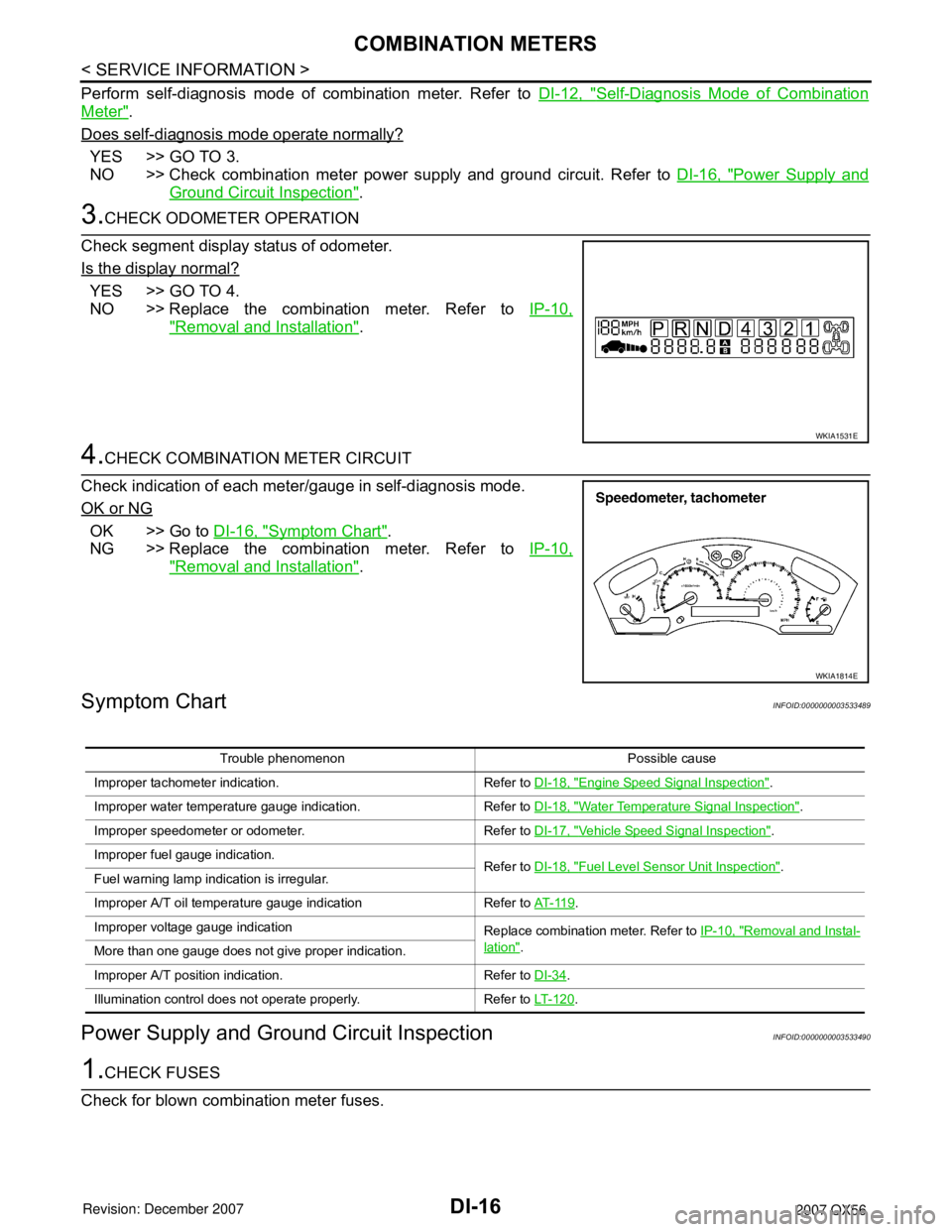
3.CHECK ODOMETER OPERATION
Check segment display status of odometer.
Is the display normal?
YES >> GO TO 4.
NO >> Replace the combination meter. Refer to IP-10,
"Removal and Installation".
4.CHECK COMBINATION METER CIRCUIT
Check indication of each meter/gauge in self-diagnosis mode.
OK or NG
OK >> Go to DI-16, "Symptom Chart".
NG >> Replace the combination meter. Refer to IP-10,
"Removal and Installation".
Symptom ChartINFOID:0000000003533489
Power Supply and Ground Circuit InspectionINFOID:0000000003533490
1.CHECK FUSES
Check for blown combination meter fuses.
WKIA1531E
WKIA1814E
Trouble phenomenon Possible cause
Improper tachometer indication. Refer to DI-18, "
Engine Speed Signal Inspection".
Improper water temperature gauge indication. Refer to DI-18, "
Water Temperature Signal Inspection".
Improper speedometer or odometer. Refer to DI-17, "
Vehicle Speed Signal Inspection".
Improper fuel gauge indication. Refer to DI-18, "
Fuel Level Sensor Unit Inspection".
Fuel warning lamp indication is irregular.
Improper A/T oil temperature gauge indication Refer to AT- 11 9
.
Improper voltage gauge indication Replace combination meter. Refer to IP-10, "
Removal and Instal-
lation".
More than one gauge does not give proper indication.
Improper A/T position indication. Refer to DI-34
.
Illumination control does not operate properly. Refer to LT- 1 2 0
.
Page 1028 of 3061

COMBINATION METERSDI-17
< SERVICE INFORMATION >
C
DE
F
G H
I
J
L
M A
B
DI
N
O P
Refer to DI-9, "Wiring Diagram - METER -".
OK or NG
OK >> GO TO 2.
NG >> If fuse is blown, be sure to eliminate caus e of malfunction before installing new fuse. Refer to PG-
3.
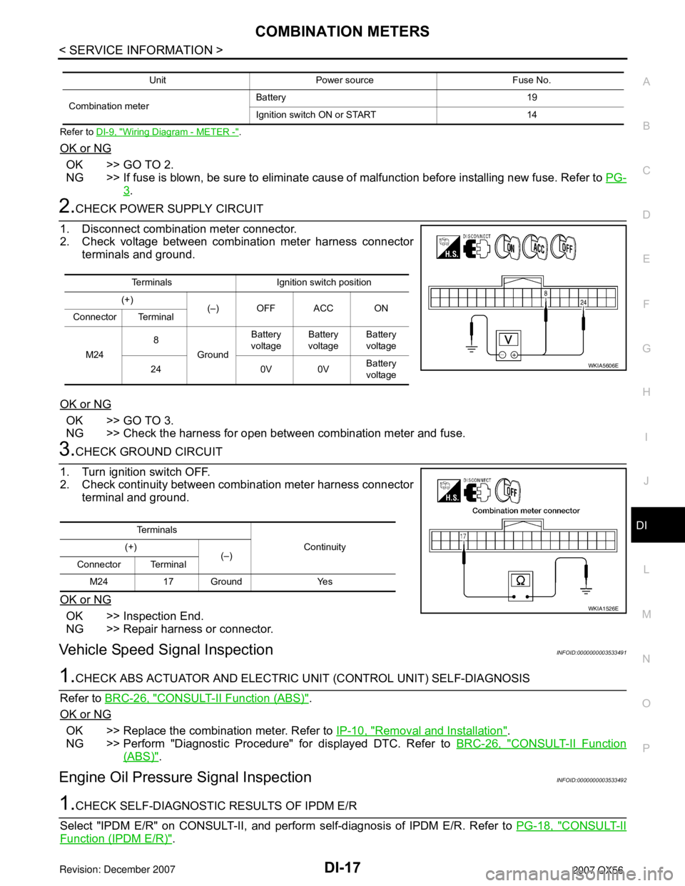
2.CHECK POWER SUPPLY CIRCUIT
1. Disconnect combination meter connector.
2. Check voltage between combination meter harness connector terminals and ground.
OK or NG
OK >> GO TO 3.
NG >> Check the harness for open between combination meter and fuse.
3.CHECK GROUND CIRCUIT
1. Turn ignition switch OFF.
2. Check continuity between combination meter harness connector terminal and ground.
OK or NG
OK >> Inspection End.
NG >> Repair harness or connector.
Vehicle Speed Signal InspectionINFOID:0000000003533491
1.CHECK ABS ACTUATOR AND ELECTRIC UNIT (CONTROL UNIT) SELF-DIAGNOSIS
Refer to BRC-26, "
CONSULT-II Function (ABS)".
OK or NG
OK >> Replace the combination meter. Refer to IP-10, "Removal and Installation".
NG >> Perform "Diagnostic Procedure" for displayed DTC. Refer to BRC-26, "
CONSULT-II Function
(ABS)".
Engine Oil Pressure Signal InspectionINFOID:0000000003533492
1.CHECK SELF-DIAGNOSTIC RESULTS OF IPDM E/R
Select "IPDM E/R" on CONSULT-II, and perform self-diagnosis of IPDM E/R. Refer to PG-18, "
CONSULT-II
Function (IPDM E/R)".
Unit Power source Fuse No.
Combination meter Battery 19
Ignition switch ON or START 14
Terminals Ignition switch position
(+) (–) OFF ACC ON
Connector Terminal
M24 8
Ground Battery
voltage Battery
voltage Battery
voltage
24 0V 0V Battery
voltage
WKIA5606E
Te r m i n a l s
Continuity
(+)
(–)
Connector Terminal
M24 17 Ground Yes
WKIA1526E
Page 1035 of 3061

DI-24
< SERVICE INFORMATION >
COMPASS AND THERMOMETER
1. Turn the ignition switch to the ON position.
2. Cool down ambient sensor 2 with water or ice.
Does the indicated temperature drop?
YES >> GO TO 2.
NO >> The system is malfunctioning. Check the system following “INSPECTION/COMPASS AND THER-
MOMETER”. Refer to "INSPECTION/COMPASS AND THERMOMETER".
2.WARM UP CHECK
1. Leave the vehicle for 10 minutes.
2. With the ignition switch in the ON position, disconnect and reconnect ambient sensor 2 connector.
Does the indicated temperature rise?
YES >> The system is OK.
NO >> The system is malfunctioning. Check the system following “INSPECTION/COMPASS AND THER-
MOMETER”. Refer to "INSPECTION/COMPASS AND THERMOMETER".
INSPECTION/COMPASS AND THERMOMETER
Calibration Procedure for CompassINFOID:0000000003533503
The difference between magnetic North and geographical North can sometimes be great enough to cause
false compass readings. In order for the compass to operate accurately in a particular zone, it must be cali-
brated using the following procedure.
Symptom Possible causes Repair order
No display at all 1. 10A fuse.
2. Ground circuit.
3. auto anti-dazzling inside mirror.1. Check 10A fuse [No. 12, located in fuse block (J/B)].
Turn the ignition switch ON and verify that battery positive
voltage is at terminal 6 of auto anti-dazzling inside mirror.
2. Check ground circuit for auto anti-dazzling inside mirror.
3. Replace auto anti-dazzling inside mirror.
Forward direction indi-
cation slips off the mark
or incorrect.1. In manual correction mode (Bar
and display vanish).
2. Zone variation change is not
done.1. Drive the vehicle and turn at an angle of 90°.
2. Perform the zone variation change.
Displays wrong temper-
ature when ambient
temperature is between
−40°C (−40°F) and
55°C (130°F)1. Check operation.
2. Ambient sensor 2 circuit.
3. Ambient sensor 2.
4. Auto anti-dazzling inside mirror.1. Perform preliminary check shown above.
2. Check harness for open or short between ambient sensor 2
and auto anti-dazzling inside mirror.
3. Replace ambient sensor 2.
4. Replace auto anti-dazzling inside mirror.
Displays SC or OC 1. Ambient sensor 2 circuit.
2. Ambient sensor 2.
3. Auto anti-dazzling inside mirror.1. Check harness for open or short between ambient sensor 2
and auto anti-dazzling inside mirror.
2. Replace ambient sensor 2.
3. Replace auto anti-dazzling inside mirror.
Page 1047 of 3061

DI-36
< SERVICE INFORMATION >
WARNING CHIME
WARNING CHIME
Component Parts and Harness Connector LocationINFOID:0000000003533510
System DescriptionINFOID:0000000003533511
FUNCTION
Power is supplied at all times
• through 50A fusible link (letter f, located in the fuse and fusible link box)
• to BCM terminal 70,
• through 10A fuse [No. 19, located in the fuse block (J/B)]
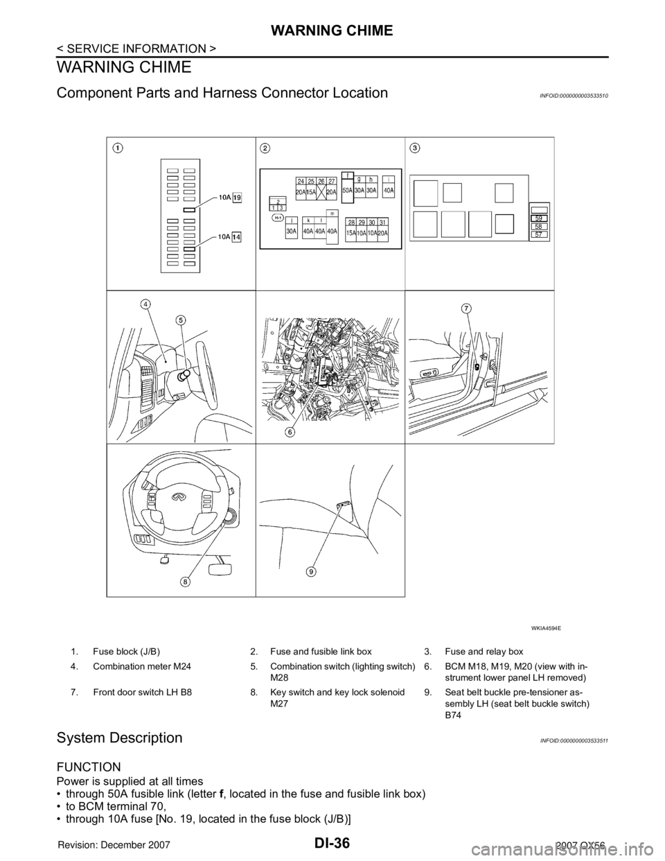
1. Fuse block (J/B) 2. Fuse and fusible link box 3. Fuse and relay box
4. Combination meter M24 5. Combination switch (lighting switch)
M286. BCM M18, M19, M20 (view with in-
strument lower panel LH removed)
7. Front door switch LH B8 8. Key switch and key lock solenoid
M279. Seat belt buckle pre-tensioner as-
sembly LH (seat belt buckle switch)
B74
WKIA4594E
Page 1048 of 3061

WARNING CHIME
DI-37
< SERVICE INFORMATION >
C
D
E
F
G
H
I
J
L
MA
B
DI
N
O
P
• to key switch and key lock solenoid terminal 3.
With ignition switch in ON or START position, power is supplied
• through 10A fuse (No. 59, located in the fuse and relay box)
• to BCM terminal 38.
Ground is supplied
• to BCM terminal 67
• through body grounds M57, M61, and M79.
NOTE:
When ignition key warning chime, light warning chime, and seat belt warning chime are required at the same
time, the priorities for each chime are the following.
1. Light warning chime
2. Ignition key warning chime
3. Seat belt warning chime
IGNITION KEY WARNING CHIME
With the key inserted in the ignition switch, the ignition switch in OFF position, and the driver's door open, the
warning chime will sound.
Power is supplied
• through key switch and key lock solenoid terminal 4
• to BCM terminal 37.
Ground is supplied
• to BCM terminal 47
• through front door switch LH terminal 2.
Front door switch LH is case grounded.
BCM detects key inserted into the ignition switch, and sends key warning signal to combination meter via CAN
communication lines. When the combination meter receives key warning signal, it sounds warning chime.
LIGHT WARNING CHIME
With the key removed from the ignition switch, the driver's door open, and the lighting switch (part of the com-
bination switch) in 1st or 2nd position, the warning chime will sound. [Except when headlamp battery saver
control operates (5 minutes after ignition switch is turned to OFF or ACC position) and headlamps do not illu-
minate.]
Signal is supplied
• from combination switch (lighting switch) terminals 1, 2, 3, 4, 5, 6, 7, 8, 9 and 10
• to BCM terminals 2, 3, 4, 5, 6, 32, 33, 34, 35 and 36.
NOTE:
BCM detected lighting switch in 1st or 2nd position. Refer to LT-72, "
Combination Switch Reading Function".
Ground is supplied
• to BCM terminal 47
• through front door switch LH terminal 2.
Front door switch LH is case grounded.
BCM detects headlamps are illuminated, and sends light warning signal to combination meter CAN communi-
cation lines. When the combination meter receives light warning signal, it sounds warning chime.
SEAT BELT WARNING CHIME
When the ignition switch is turned ON with the seat belt unfastened [seat belt buckle pre-tensioner assembly
LH (seat belt buckle switch) unfastened], warning chime will sound for approximately 6 seconds.
Ground is supplied
• to combination meter terminal 27
• through seat belt buckle pre-tensioner assembly LH (seat belt buckle switch) terminal 4.
Seat belt buckle pre-tensioner assembly LH (seat belt buckle switch) terminal 3 is grounded through body
grounds B7 and B19.
The combination meter sends seat belt buckle switch LH unfastened signal to BCM via CAN communication
line.
BCM receives seat belt buckle pre-tensioner assembly LH (seat belt buckle switch) unfastened signal from
combination meter via CAN communication line, and sends seat belt warning signal to the combination meter
via CAN communication line. When the combination meter receives the seat belt warning signal, it sounds the
warning chime. The BCM controls the (6 second) duration of the seat belt warning chime.
CAN Communication System DescriptionINFOID:0000000003533512
Refer to LAN-4.
Page 1053 of 3061

DI-42
< SERVICE INFORMATION >
WARNING CHIME
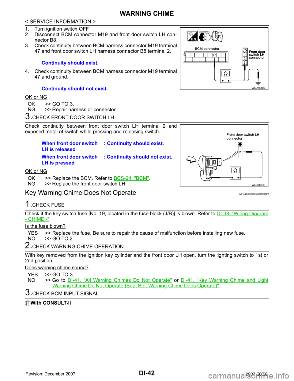
1. Turn ignition switch OFF.
2. Disconnect BCM connector M19 and front door switch LH con-
nector B8.
3. Check continuity between BCM harness connector M19 terminal
47 and front door switch LH harness connector B8 terminal 2.
4. Check continuity between BCM harness connector M19 terminal
47 and ground.
OK or NG
OK >> GO TO 3.
NG >> Repair harness or connector.
3.CHECK FRONT DOOR SWITCH LH
Check continuity between front door switch LH terminal 2 and
exposed metal of switch while pressing and releasing switch.
OK or NG
OK >> Replace the BCM. Refer to BCS-24, "BCM".
NG >> Replace the front door switch LH.
Key Warning Chime Does Not OperateINFOID:0000000003533521
1.CHECK FUSE
Check if the key switch fuse [No. 19, located in the fuse block (J/B)] is blown. Refer to DI-38, "
Wiring Diagram
- CHIME -".
Is the fuse blown?
YES >> Replace the fuse. Be sure to repair the cause of malfunction before installing new fuse.
NO >> GO TO 2.
2.CHECK WARNING CHIME OPERATION
With key removed from the ignition key cylinder and the front door LH open, turn the lighting switch to 1st or
2nd position.
Does warning chime sound?
YES >> GO TO 3.
NO >> Go to DI-41, "
All Warning Chimes Do Not Operate" or DI-41, "Key Warning Chime and Light
Warning Chime Do Not Operate (Seat Belt Warning Chime Does Operate)".
3.CHECK BCM INPUT SIGNAL
With CONSULT-IIContinuity should exist.
Continuity should not exist.
WKIA1516E
When front door switch
LH is released: Continuity should exist.
When front door switch
LH is pressed: Continuity should not exist.
WKIA2023E