2007 INFINITI QX56 lock
[x] Cancel search: lockPage 1852 of 3061
EM-82
< SERVICE INFORMATION >
CYLINDER BLOCK
ASSEMBLY
1. Fully air-blow the coolant and oil passages in the cylinder block, cylinder bore, and crankcase to remove
any foreign material.
CAUTION:
Use goggles to protect your eyes.
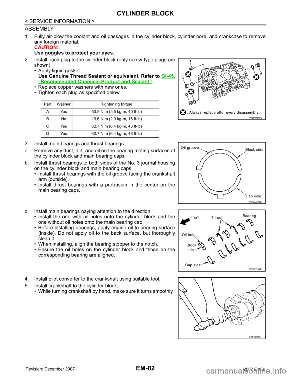
2. Install each plug to the cylinder block (only screw-type plugs are
shown).
• Apply liquid gasket.
Use Genuine Thread Sealant or equivalent. Refer to GI-45,
"Recommended Chemical Product and Sealant".
• Replace copper washers with new ones.
• Tighten each plug as specified below.
3. Install main bearings and thrust bearings.
a. Remove any dust, dirt, and oil on the bearing mating surfaces of
the cylinder block and main bearing caps.
b. Install thrust bearings to both sides of the No. 3 journal housing
on the cylinder block and main bearing caps
• Install thrust bearings with the oil groove facing the crankshaft
arm (outside).
• Install thrust bearings with a protrusion in the center on the
main bearing caps.
c. Install main bearings paying attention to the direction.
• Install the one with oil holes onto the cylinder block and the
one without oil holes onto the main bearing cap.
• Before installing bearings, apply engine oil to bearing surface
(inside). Do not apply oil to the back surface, but thoroughly
clean it.
• When installing, align the bearing stopper to the notch.
• Ensure the oil holes on the cylinder block and those on the
corresponding bearing are aligned.
4. Install pilot converter to the crankshaft using suitable tool.
5. Install crankshaft to the cylinder block.
• While turning crankshaft by hand, make sure it turns smoothly.
Part Washer Tightening torque
A Yes 53.9 N·m (5.5 kg-m, 40 ft-lb)
B No 19.6 N·m (2.0 kg-m, 15 ft-lb)
C Yes 62.7 N·m (6.4 kg-m, 46 ft-lb)
D Yes 62.7 N·m (6.4 kg-m, 46 ft-lb)
WBIA0419E
PBIC0093E
PBIC0094E
EMP0569D
Page 1853 of 3061
CYLINDER BLOCK
EM-83
< SERVICE INFORMATION >
C
D
E
F
G
H
I
J
K
L
MA
EM
N
P O
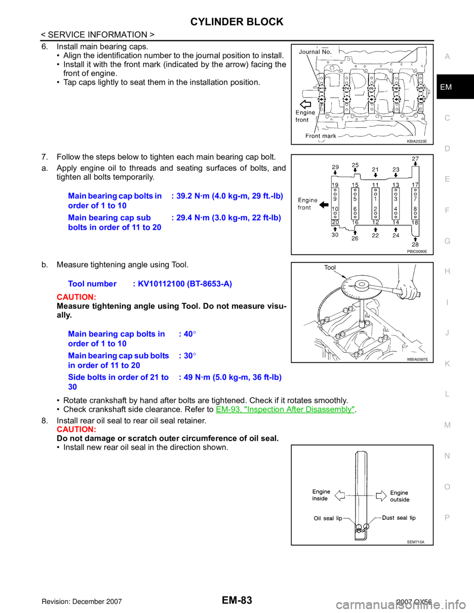
6. Install main bearing caps.
• Align the identification number to the journal position to install.
• Install it with the front mark (indicated by the arrow) facing the
front of engine.
• Tap caps lightly to seat them in the installation position.
7. Follow the steps below to tighten each main bearing cap bolt.
a. Apply engine oil to threads and seating surfaces of bolts, and
tighten all bolts temporarily.
b. Measure tightening angle using Tool.
CAUTION:
Measure tightening angle using Tool. Do not measure visu-
ally.
• Rotate crankshaft by hand after bolts are tightened. Check if it rotates smoothly.
• Check crankshaft side clearance. Refer to EM-93, "
Inspection After Disassembly".
8. Install rear oil seal to rear oil seal retainer.
CAUTION:
Do not damage or scratch outer circumference of oil seal.
• Install new rear oil seal in the direction shown.
KBIA2533E
Main bearing cap bolts in
order of 1 to 10: 39.2 N·m (4.0 kg-m, 29 ft.-lb)
Main bearing cap sub
bolts in order of 11 to 20: 29.4 N·m (3.0 kg-m, 22 ft-lb)
PBIC0090E
Tool number : KV10112100 (BT-8653-A)
Main bearing cap bolts in
order of 1 to 10: 40°
Main bearing cap sub bolts
in order of 11 to 20: 30°
Side bolts in order of 21 to
30: 49 N·m (5.0 kg-m, 36 ft-lb)
WBIA0597E
SEM715A
Page 1854 of 3061
EM-84
< SERVICE INFORMATION >
CYLINDER BLOCK
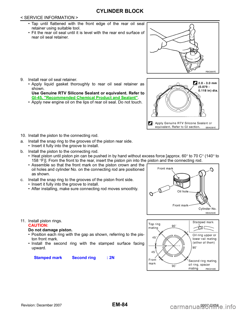
• Tap until flattened with the front edge of the rear oil seal
retainer using suitable tool.
• Fit the rear oil seal until it is level with the rear end surface of
rear oil seal retainer.
9. Install rear oil seal retainer.
• Apply liquid gasket thoroughly to rear oil seal retainer as
shown.
Use Genuine RTV Silicone Sealant or equivalent. Refer to
GI-45, "
Recommended Chemical Product and Sealant".
• Apply new engine oil on the lips of rear oil seal. Do not touch.
10. Install the piston to the connecting rod.
a. Install the snap ring to the grooves of the piston rear side.
• Insert it fully into the groove to install.
b. Install the piston to the connecting rod.
• Heat piston until piston pin can be pushed in by hand without excess force [approx. 60° to 70 C° (140° to
158 °F)]. From the front to the rear, insert the piston pin into the piston and the connecting rod.
• Assemble so that the front mark on the piston crown and the
oil holes and cylinder No. on the connecting rod are positioned
as shown.
c. Install the snap ring to the grooves of the piston front side.
• Insert it fully into the groove to install.
• After installing, make sure connecting rod moves smoothly.
11. Install piston rings.
CAUTION:
Do not damage piston.
• Position each ring with the gap as shown, referring to the pis-
ton front mark.
• Install the second ring with the stamped surface facing
upward.
PBIC0097E
SBIA0391E
KBIA2534E
Stamped mark Second ring : 2N
PBIC0100E
Page 1855 of 3061
CYLINDER BLOCK
EM-85
< SERVICE INFORMATION >
C
D
E
F
G
H
I
J
K
L
MA
EM
N
P O
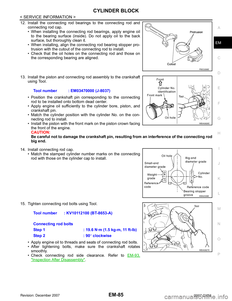
12. Install the connecting rod bearings to the connecting rod and
connecting rod cap.
• When installing the connecting rod bearings, apply engine oil
to the bearing surface (inside). Do not apply oil to the back
surface, but thoroughly clean it.
• When installing, align the connecting rod bearing stopper pro-
trusion with the cutout of the connecting rod to install.
• Check that the oil holes on the connecting rod and those on
the corresponding bearing are aligned.
13. Install the piston and connecting rod assembly to the crankshaft
using Tool.
• Position the crankshaft pin corresponding to the connecting
rod to be installed onto bottom dead center.
• Apply engine oil sufficiently to the cylinder bore, piston, and
crankshaft pin.
• Match the cylinder position with the cylinder No. on the con-
necting rod to install.
• Install the piston with the front mark on the piston crown facing
the front of the engine.
CAUTION:
Be careful not to damage the crankshaft pin, resulting from an interference of the connecting rod
big end.
14. Install connecting rod cap.
• Match the stamped cylinder number marks on the connecting
rod with those on the cylinder cap to install.
15. Tighten connecting rod bolts using Tool.
• Apply engine oil to threads and seats of connecting rod bolts.
• After tightening bolts, make sure the crankshaft rotates
smoothly.
• Check connecting rod side clearance. Refer to EM-93,
"Inspection After Disassembly".
PBIC0266E
Tool number : EM03470000 (J-8037)
WBIA0626E
KBIA2536E
Tool number : KV10112100 (BT-8653-A)
Connecting rod bolts
Step 1 : 19.6 N·m (1.5 kg-m, 11 ft-lb)
Step 2 : 90° clockwise
WBIA0627E
Page 1856 of 3061
EM-86
< SERVICE INFORMATION >
CYLINDER BLOCK
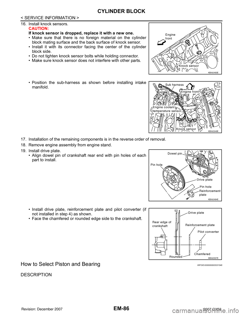
16. Install knock sensors.
CAUTION:
If knock sensor is dropped, replace it with a new one.
• Make sure that there is no foreign material on the cylinder
block mating surface and the back surface of knock sensor.
• Install it with its connector facing the center of the cylinder
block side.
• Do not tighten knock sensor bolts while holding connector.
• Make sure knock sensor does not interfere with other parts.
• Position the sub-harness as shown before installing intake
manifold.
17. Installation of the remaining components is in the reverse order of removal.
18. Remove engine assembly from engine stand.
19. Install drive plate.
• Align dowel pin of crankshaft rear end with pin holes of each
part to install.
• Install drive plate, reinforcement plate and pilot converter (if
not installed in step 4) as shown.
• Face the chamfered or rounded edge side to the crankshaft.
How to Select Piston and BearingINFOID:0000000003531546
DESCRIPTION
KBIA2493E
KBIA2549E
KBIA2494E
KBIA2537E
Page 1857 of 3061
CYLINDER BLOCK
EM-87
< SERVICE INFORMATION >
C
D
E
F
G
H
I
J
K
L
MA
EM
N
P O
*For the service parts, the grade for fitting cannot be selected between a piston pin and a connecting rod.
(Only 0 grade is available.) The information at the shipment from the plant is described as a reference.
• The identification grade stamped on each part is the grade for the dimension measured in new condition.
This grade cannot apply to reused parts.
• For reused or repaired parts, measure the dimension accurately. Determine the grade by comparing the
measurement with the values of each selection table.
• For details of the measurement method of each part, the reuse standards, and the selection method of the
selective fitting parts, refer to the text.
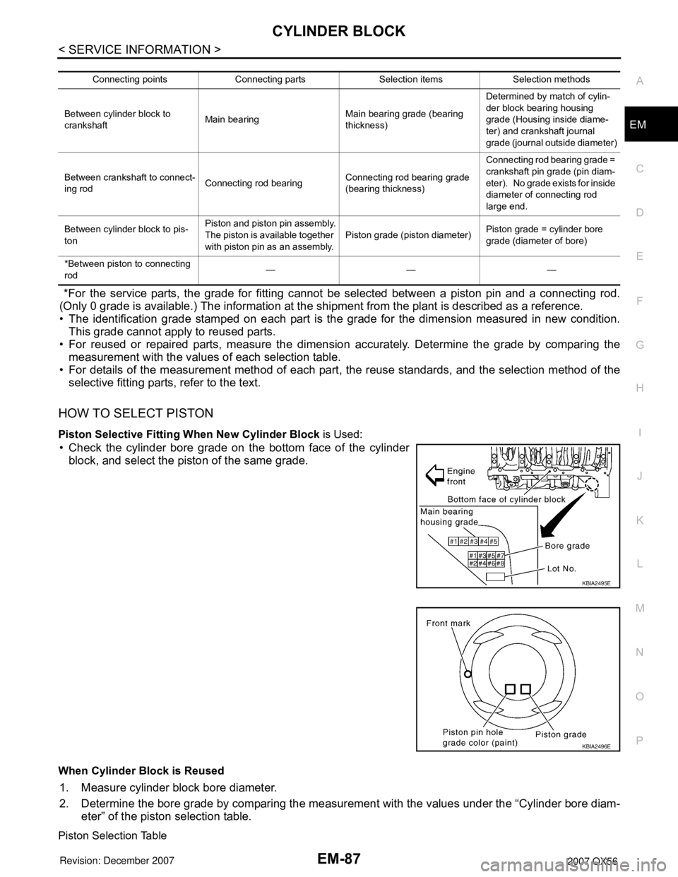
HOW TO SELECT PISTON
Piston Selective Fitting When New Cylinder Block is Used:
• Check the cylinder bore grade on the bottom face of the cylinder
block, and select the piston of the same grade.
When Cylinder Block is Reused
1. Measure cylinder block bore diameter.
2. Determine the bore grade by comparing the measurement with the values under the “Cylinder bore diam-
eter” of the piston selection table.
Piston Selection Table
Connecting points Connecting parts Selection items Selection methods
Between cylinder block to
crankshaftMain bearingMain bearing grade (bearing
thickness)Determined by match of cylin-
der block bearing housing
grade (Housing inside diame-
ter) and crankshaft journal
grade (journal outside diameter)
Between crankshaft to connect-
ing rodConnecting rod bearingConnecting rod bearing grade
(bearing thickness)Connecting rod bearing grade =
crankshaft pin grade (pin diam-
eter). No grade exists for inside
diameter of connecting rod
large end.
Between cylinder block to pis-
tonPiston and piston pin assembly.
The piston is available together
with piston pin as an assembly.Piston grade (piston diameter)Piston grade = cylinder bore
grade (diameter of bore)
*Between piston to connecting
rod———
KBIA2495E
KBIA2496E
Page 1858 of 3061
EM-88
< SERVICE INFORMATION >
CYLINDER BLOCK
Unit: mm (in)
NOTE:
• The piston is available together with piston pin as an assembly.
• The piston pin (piston pin bore) grade is provided only for the parts installed at the plant. For service parts,
grades can be selected.
• Hone the cylinder to obtain specified clearance between the piston and cylinder bore.
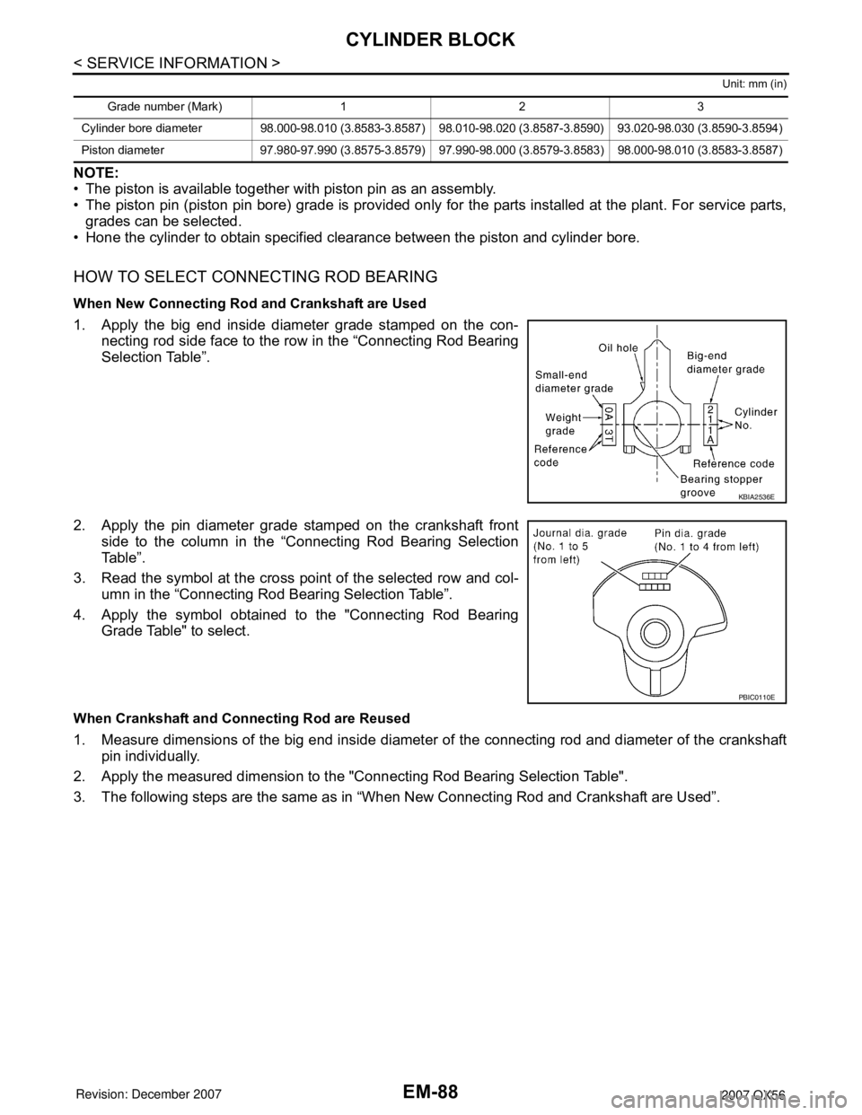
HOW TO SELECT CONNECTING ROD BEARING
When New Connecting Rod and Crankshaft are Used
1. Apply the big end inside diameter grade stamped on the con-
necting rod side face to the row in the “Connecting Rod Bearing
Selection Table”.
2. Apply the pin diameter grade stamped on the crankshaft front
side to the column in the “Connecting Rod Bearing Selection
Table”.
3. Read the symbol at the cross point of the selected row and col-
umn in the “Connecting Rod Bearing Selection Table”.
4. Apply the symbol obtained to the "Connecting Rod Bearing
Grade Table" to select.
When Crankshaft and Connecting Rod are Reused
1. Measure dimensions of the big end inside diameter of the connecting rod and diameter of the crankshaft
pin individually.
2. Apply the measured dimension to the "Connecting Rod Bearing Selection Table".
3. The following steps are the same as in “When New Connecting Rod and Crankshaft are Used”.
Grade number (Mark) 1 2 3
Cylinder bore diameter 98.000-98.010 (3.8583-3.8587) 98.010-98.020 (3.8587-3.8590) 93.020-98.030 (3.8590-3.8594)
Piston diameter 97.980-97.990 (3.8575-3.8579) 97.990-98.000 (3.8579-3.8583) 98.000-98.010 (3.8583-3.8587)
KBIA2536E
PBIC0110E
Page 1859 of 3061
CYLINDER BLOCK
EM-89
< SERVICE INFORMATION >
C
D
E
F
G
H
I
J
K
L
MA
EM
N
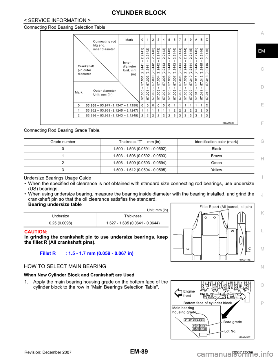
P O Connecting Rod Bearing Selection Table
Connecting Rod Bearing Grade Table.
Undersize Bearings Usage Guide
• When the specified oil clearance is not obtained with standard size connecting rod bearings, use undersize
(US) bearings.
• When using undersize bearing, measure the bearing inside diameter with the bearing installed, and grind the
crankshaft pin so that the oil clearance satisfies the standard.
Bearing undersize table
Unit: mm (in)
CAUTION:
In grinding the crankshaft pin to use undersize bearings, keep
the fillet R (All crankshaft pins).
HOW TO SELECT MAIN BEARING
When New Cylinder Block and Crankshaft are Used
1. Apply the main bearing housing grade on the bottom face of the
cylinder block to the row in "Main Bearings Selection Table".
KBIA2538E
Grade number Thickness “T” mm (in) Identification color (mark)
0 1.500 - 1.503 (0.0591 - 0.0592) Black
1 1.503 - 1.506 (0.0592 - 0.0593) Brown
2 1.506 - 1.509 (0.0593 - 0.0594) Green
3 1.509 - 1.512 (0.0594 - 0.0595) Yellow
Undersize Thickness
0.25 (0.0098) 1.627 - 1.635 (0.0641 - 0.0644)
Fillet R : 1.5 - 1.7 mm (0.059 - 0.067 in)
PBIC0111E
KBIA2495E