2007 INFINITI QX56 lock
[x] Cancel search: lockPage 1771 of 3061
EM-1
ENGINE
C
DE
F
G H
I
J
K L
M
SECTION EM
A
EM
N
O P
CONTENTS
ENGINE MECHANICAL
SERVICE INFORMATION .. ..........................3
PRECAUTIONS .............................................. .....3
Precaution for Supplemental Restraint System
(SRS) "AIR BAG" and "SEAT BELT PRE-TEN-
SIONER" ............................................................. ......
3
Precaution for Drain Engine Coolant .........................3
Precaution for Disconnecting Fuel Piping .................3
Precaution for Removal and Disassembly ................3
Precaution for Inspection, Repair and Replace-
ment .................................................................... ......
3
Precaution for Assembly and Installation ..................3
Parts Requiring Angular Tightening ..........................4
Precaution for Liquid Gasket ............................... ......4
PREPARATION ...................................................6
Special Service Tool ........................................... ......6
Commercial Service Tool ..........................................8
NOISE, VIBRATION AND HARSHNESS
(NVH) TROUBLESHOOTING ............................
10
NVH Troubleshooting - Engine Noise ................. ....10
Use the Chart Below to Help You Find the Cause
of the Symptom .......................................................
11
ENGINE ROOM COVER ....................................12
Removal and Installation .........................................12
DRIVE BELTS ................................................ ....13
Checking Drive Belts ........................................... ....13
Removal and Installation .........................................13
Drive Belt Auto Tensioner and Idler Pulley ......... ....14
AIR CLEANER AND AIR DUCT ........................15
Removal and Installation .........................................15
Removal and Installation (Viscous paper type) ... ....15
INTAKE MANIFOLD ...........................................17
Removal and Installation .........................................17
EXHAUST MANIFOLD AND THREE WAY
CATALYST ..................................................... ....
21
Removal and Installation ..................................... ....21
OIL PAN AND OIL STRAINER .........................24
Removal and Installation .........................................24
IGNITION COIL .................................................28
Removal and Installation .........................................28
SPARK PLUG ...................................................29
Removal and Installation .........................................29
FUEL INJECTOR AND FUEL TUBE ................31
Removal and Installation .........................................31
ROCKER COVER .............................................35
Removal and Installation .........................................35
TIMING CHAIN ..................................................37
Exploded View ..................................................... ....37
Removal and Installation .........................................38
CAMSHAFT .......................................................46
Removal and Installation .........................................46
Inspection after Installation ......................................55
Valve Clearance .................................................. ....56
OIL SEAL ..........................................................61
Removal and Installation of Valve Oil Seal ..............61
Removal and Installation of Front Oil Seal ..............61
Removal and Installation of Rear Oil Seal ...............62
CYLINDER HEAD .............................................64
On-Vehicle Service .............................................. ....64
Removal and Installation .........................................65
Disassembly and Assembly .....................................67
Inspection After Disassembly ..................................69
ENGINE ASSEMBLY ........................................74
Removal and Installation ..................................... ....74
CYLINDER BLOCK ...........................................78
Disassembly and Assembly .....................................78
How to Select Piston and Bearing ....................... ....86
Page 1773 of 3061
PRECAUTIONSEM-3
< SERVICE INFORMATION >
C
DE
F
G H
I
J
K L
M A
EM
NP
O
SERVICE INFORMATION
PRECAUTIONS
Precaution for Supplemental
Restraint System (SRS) "AIR BAG" and "SEAT BELT
PRE-TENSIONER"
INFOID:0000000003531508
The Supplemental Restraint System such as “A IR BAG” and “SEAT BELT PRE-TENSIONER”, used along
with a front seat belt, helps to reduce the risk or severi ty of injury to the driver and front passenger for certain
types of collision. This system includes seat belt switch inputs and dual stage front air bag modules. The SRS
system uses the seat belt switches to determine the front air bag deployment, and may only deploy one front
air bag, depending on the severity of a collision and w hether the front occupants are belted or unbelted.
Information necessary to service the system safely is included in the SRS and SB section of this Service Man-
ual.
WARNING:
• To avoid rendering the SRS inoper ative, which could increase the risk of personal injury or death in
the event of a collision which would result in air bag inflation, all maintenance must be performed by
an authorized NISSAN/INFINITI dealer.
• Improper maintenance, including in correct removal and installation of the SRS, can lead to personal
injury caused by unintentional act ivation of the system. For removal of Spiral Cable and Air Bag
Module, see the SRS section.
• Do not use electrical test equipm ent on any circuit related to the SRS unless instructed to in this
Service Manual. SRS wiring harnesses can be identi fied by yellow and/or orange harnesses or har-
ness connectors.
Precaution for Drain Engine CoolantINFOID:0000000003531509
Drain engine coolant when engine is cooled.
Precaution for Disco nnecting Fuel PipingINFOID:0000000003531510
• Before starting work, make sure no fire or spark producing items are in the work area.
• Release fuel pressure before disconnecting and disassembly.
• After disconnecting pipes, plug openings to stop fuel leakage.
Precaution for Removal and DisassemblyINFOID:0000000003531511
• When instructed to use special service tools, use the spec ified tools. Always be careful to work safely, avoid
forceful or uninstructed operations.
• Exercise maximum care to avoid damage to mating or sliding surfaces.
• Cover openings of engine system with tape or the equiva lent, if necessary, to seal out foreign materials.
• Mark and arrange disassembly parts in an organized way for easy troubleshooting and assembly.
• When loosening nuts and bolts, as a basic rule, start with the one furthest outside, then the one diagonally
opposite, and so on. If the order of loosening is specif ied, do exactly as specified. Power tools may be used
where noted in the step.
Precaution for Inspection, Repair and ReplacementINFOID:0000000003531512
Before repairing or replacing, thoroughly inspect parts. Inspect new replacement parts in the same way, and
replace if necessary.
Precaution for Assembly and InstallationINFOID:0000000003531513
• Use torque wrench to tighten bolts or nuts to specification.
• When tightening nuts and bolts, as a basic rule, equally tighten in several different steps starting with the ones in center, then ones on inside and outside diagonally in this order. If the order of tightening is specified,
do exactly as specified.
• Replace with new gasket, packing, oil seal or O-ring.
• Thoroughly wash, clean, and air-blow each part. Carefully check engine oil or engine coolant passages for any restriction and blockage.
• Avoid damaging sliding or mating surfaces. Completely remove foreign materials such as cloth lint or dust. Before assembly, oil sliding surfaces well.
Page 1781 of 3061

NOISE, VIBRATION AND HARSHNESS (NVH) TROUBLESHOOTINGEM-11
< SERVICE INFORMATION >
C
DE
F
G H
I
J
K L
M A
EM
NP
O
Use the Chart Below to Help You
Find the Cause of the SymptomINFOID:0000000003531519
1. Locate the area where noise occurs.
2. Confirm the type of noise.
3. Specify the operating condition of engine.
4. Check specified noise source.
If necessary, repair or replace these parts.
A: Closely related B: Related C: Sometimes related —: Not relatedB. Tappet noise C. Camshaft bearing noise D. Valve mechanism
E. Rotation mechanism F. Piston pin noise G. Piston slap noise
H. Main bearing noise I. Connecting rod bearing noise J. Drive belt noise (slipping)
K. Drive belt noise (stick/slipping) L. Water pump noise M. Timing chain and chain tensioner noise
Location of noise Ty p e o f
noise Operating condition of engine
Source of noise Check item
Refer-
ence page
Be-
fore
warm- up After
warm-
up When
start-
ing When
idling When
racing While
driv-
ing
Top of en-
gine
Rocker cov-
er
Cylinder
head Ticking or
clicking
C A — A B — Tappet noise Valve clearance
EM-56
Rattle C A — A B CCamshaft
bearing noiseCamshaft journal clear-
ance
Camshaft runout EM-46EM-46
Crankshaft
pulley
Cylinder
block (Side
of engine)
Oil panSlap or
knock
—A—B B— Piston pin
noisePiston and piston pin
clearance
Connecting rod bushing
clearance EM-93
EM-93
Slap or
rap
A——B B A Piston slap
noisePiston-to-bore clear-
ance
Piston ring side clear-
ance
Piston ring end gap
Connecting rod bend
and torsion EM-93EM-93
EM-93
EM-93
Knock A B C B B B
Connecting
rod bearing
noiseConnecting rod bushing
oil clearance (Small
end)
Connecting rod bearing
clearance (Big end)
EM-93EM-93
Knock A B — A B C
Main bearing
noiseMain bearing oil clear-
ance
Crankshaft runout EM-93EM-93
Front of en-
gine
Chain case
cover
Front coverTapping
or ticking
AA—BBB Timing chain
and chain
tensioner
noiseTiming chain cracks
and wear
Timing chain tensioner
operation
EM-38
EM-38
Front of en-
gineSqueak-
ing or
fizzing
AB—B—C
Drive belts
(Sticking or
slipping)Drive belts deflection
EM-13Creaking A B A B A B Drive belts
(Slipping)Idler pulley bearing op-
eration
Squall
Creaking AB—BAB Water pump
noiseWater pump operation
EM-38
Rattle — — A — — — VTC VTC lockpin clearance EM-55
Page 1784 of 3061
EM-14
< SERVICE INFORMATION >
DRIVE BELTS
INSTALLATION
Installation is in the reverse order of removal.
CAUTION:
Make sure belt is securely installed around all pulleys.
• Rotate the crankshaft pulley several turns clockwise to equalize belt tension between pulleys.
• Make sure belt tension is within the allowable working range, using the indicator notch on the drive belt auto
tensioner. Refer to EM-13, "
Checking Drive Belts".
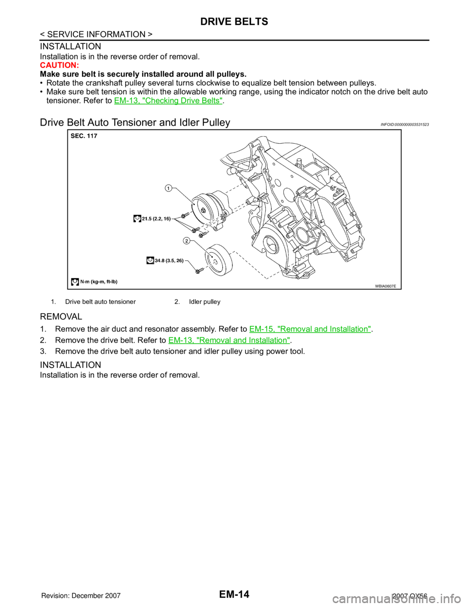
Drive Belt Auto Tensioner and Idler PulleyINFOID:0000000003531523
REMOVAL
1. Remove the air duct and resonator assembly. Refer to EM-15, "Removal and Installation".
2. Remove the drive belt. Refer to EM-13, "
Removal and Installation".
3. Remove the drive belt auto tensioner and idler pulley using power tool.
INSTALLATION
Installation is in the reverse order of removal.
WBIA0607E
1. Drive belt auto tensioner 2. Idler pulley
Page 1795 of 3061
OIL PAN AND OIL STRAINEREM-25
< SERVICE INFORMATION >
C
DE
F
G H
I
J
K L
M A
EM
NP
O
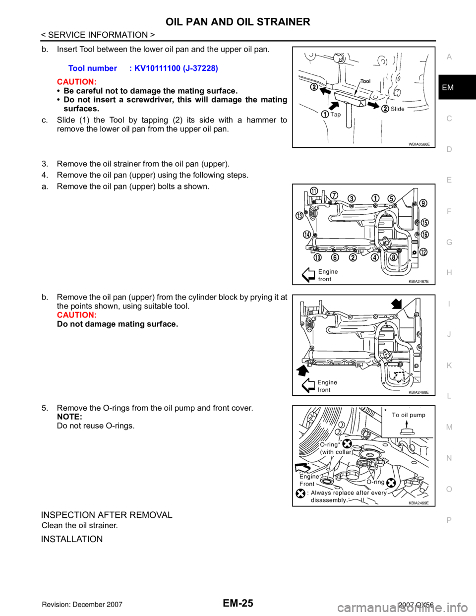
b. Insert Tool between the lower oil pan and the upper oil pan.
CAUTION:
• Be careful not to damage the mating surface.
• Do not insert a screwdriver, this will damage the matingsurfaces.
c. Slide (1) the Tool by tapping (2) its side with a hammer to remove the lower oil pan from the upper oil pan.
3. Remove the oil strainer from the oil pan (upper).
4. Remove the oil pan (upper) using the following steps.
a. Remove the oil pan (upper) bolts a shown.
b. Remove the oil pan (upper) from the cylinder block by prying it at the points shown, using suitable tool.
CAUTION:
Do not damage mating surface.
5. Remove the O-rings from the oil pump and front cover. NOTE:
Do not reuse O-rings.
INSPECTION AFTER REMOVAL
Clean the oil strainer.
INSTALLATION
Tool number : KV10111100 (J-37228)
WBIA0566E
KBIA2467E
KBIA2468E
KBIA2469E
Page 1809 of 3061
TIMING CHAINEM-39
< SERVICE INFORMATION >
C
DE
F
G H
I
J
K L
M A
EM
NP
O
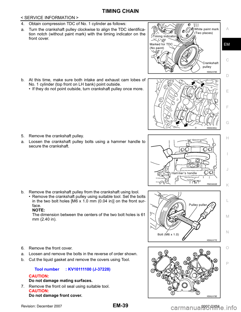
4. Obtain compression TDC of No. 1 cylinder as follows:
a. Turn the crankshaft pulley clockwise to align the TDC identifica-
tion notch (without paint mark) with the timing indicator on the
front cover.
b. At this time, make sure both intake and exhaust cam lobes of No. 1 cylinder (top front on LH bank) point outside.
• If they do not point outside, turn crankshaft pulley once more.
5. Remove the crankshaft pulley.
a. Loosen the crankshaft pulley bolts using a hammer handle to secure the crankshaft.
b. Remove the crankshaft pulley from the crankshaft using tool. • Remove the crankshaft pulley using suitable tool. Set the boltsin the two bolt holes [M6 x 1.0 mm (0.04 in)] on the front sur-
face.
NOTE:
The dimension between the centers of the two bolt holes is 61
mm (2.40 in).
6. Remove the front cover.
a. Loosen and remove the bolts in the reverse of order shown.
b. Cut the liquid gasket and remove the covers using Tool. CAUTION:
Do not damage mating surfaces.
7. Remove the front oil seal using suitable tool. CAUTION:
Do not damage front cover.
KBIA2476E
KBIA0400J
PBIC0053E
KBIA2477E
Tool number : KV10111100 (J-37228)
KBIA2478E
Page 1812 of 3061
EM-42
< SERVICE INFORMATION >
TIMING CHAIN
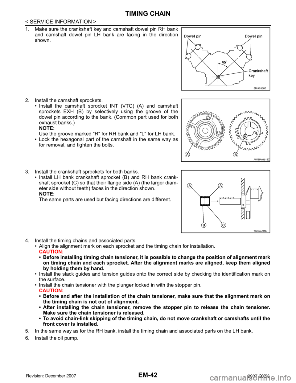
1. Make sure the crankshaft key and camshaft dowel pin RH bankand camshaft dowel pin LH bank are facing in the direction
shown.
2. Install the camshaft sprockets. • Install the camshaft sprocket INT (VTC) (A) and camshaftsprockets EXH (B) by selectively using the groove of the
dowel pin according to the bank . (Common part used for both
exhaust banks.)
NOTE:
Use the groove marked "R" for RH bank and "L" for LH bank.
• Lock the hexagonal part of the camshaft in the same way as for removal, and tighten the bolts.
3. Install the crankshaft sprockets for both banks. • Install LH bank crankshaft sprocket (B) and RH bank crank-shaft sprocket (C) so that their flange side (A) (the larger diam-
eter side without teeth) faces in the direction shown.
NOTE:
The same parts are used but facing directions are different.
4. Install the timing chains and associated parts. • Align the alignment mark on each sprocket and the timing chain for installation.
CAUTION:
• Before installing timing chain tens ioner, it is possible to change the position of alignment mark
on timing chain and each sprocket. After the al ignment marks are aligned, keep them aligned
by holding them by hand.
• Install the slack guides and tension guides onto the co rrect side by checking the identification mark on
the surface.
• Install the chain tensioner with the plunger locked in with the stopper pin.
CAUTION:
• Before and after the installation of the chain tensioner, make sure that the alignment mark on
the timing chain is not out of alignment.
• After installing the chain tensioner, remove the stopper pin to release the chain tensioner.
Make sure the chain tensioner is released.
• To avoid chain-link skipping of the timing chain, do not move crankshaft or camshafts until the
front cover is installed.
5. In the same way as for the RH bank, install the timing chain and associated parts on the LH bank.
6. Install the oil pump.
SBIA0356E
AWBIA0151ZZ
WBIA0701E
Page 1813 of 3061
TIMING CHAINEM-43
< SERVICE INFORMATION >
C
DE
F
G H
I
J
K L
M A
EM
NP
O
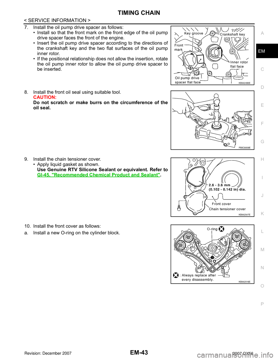
7. Install the oil pump drive spacer as follows:
• Install so that the front mark on the front edge of the oil pump
drive spacer faces the front of the engine.
• Insert the oil pump drive spacer according to the directions of
the crankshaft key and the two flat surfaces of the oil pump
inner rotor.
• If the positional relationship does not allow the insertion, rotate the oil pump inner rotor to allow the oil pump drive spacer to
be inserted.
8. Install the front oil seal using suitable tool. CAUTION:
Do not scratch or make burrs on the circumference of the
oil seal.
9. Install the chain tensioner cover. • Apply liquid gasket as shown.
Use Genuine RTV Silicone Seal ant or equivalent. Refer to
GI-45, "
Recommended Chemical Product and Sealant".
10. Install the front cover as follows:
a. Install a new O-ring on the cylinder block.
KBIA2490E
PBIC0059E
KBIA2547E
KBIA2516E