Page 1559 of 3061
EC-476
< SERVICE INFORMATION >
DTC P1217 ENGINE OVER TEMPERATURE
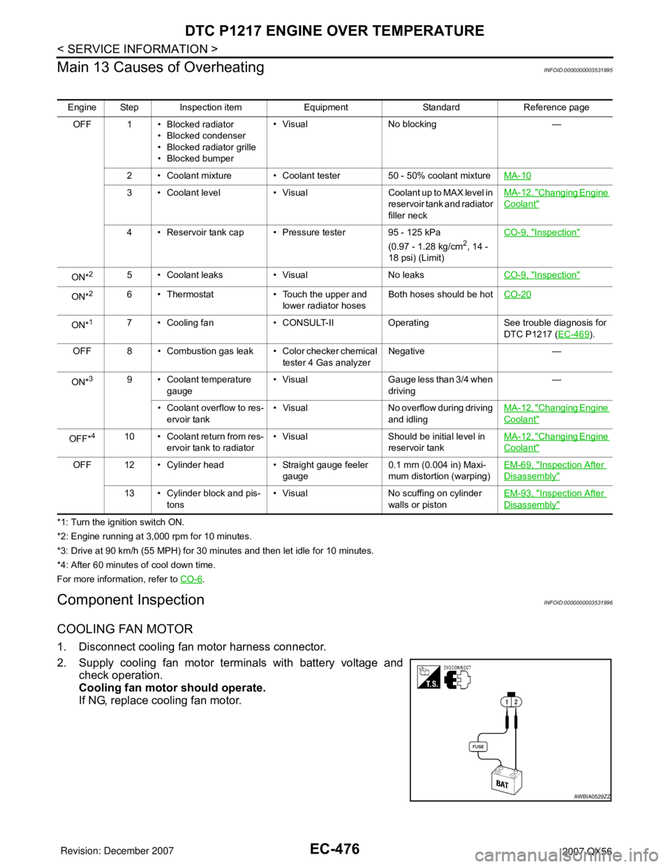
Main 13 Causes of Overheating
INFOID:0000000003531995
*1: Turn the ignition switch ON.
*2: Engine running at 3,000 rpm for 10 minutes.
*3: Drive at 90 km/h (55 MPH) for 30 minutes and then let idle for 10 minutes.
*4: After 60 minutes of cool down time.
For more information, refer to CO-6
.
Component InspectionINFOID:0000000003531996
COOLING FAN MOTOR
1. Disconnect cooling fan motor harness connector.
2. Supply cooling fan motor terminals with battery voltage and
check operation.
Cooling fan motor should operate.
If NG, replace cooling fan motor.
Engine Step Inspection item Equipment Standard Reference page
OFF 1 • Blocked radiator
• Blocked condenser
• Blocked radiator grille
• Blocked bumper• Visual No blocking —
2 • Coolant mixture • Coolant tester 50 - 50% coolant mixtureMA-10
3 • Coolant level • Visual Coolant up to MAX level in
reservoir tank and radiator
filler neckMA-12, "Changing Engine
Coolant"
4 • Reservoir tank cap • Pressure tester 95 - 125 kPa
(0.97 - 1.28 kg/cm2, 14 -
18 psi) (Limit)CO-9, "
Inspection"
ON*25 • Coolant leaks • Visual No leaksCO-9, "Inspection"
ON*26 • Thermostat • Touch the upper and
lower radiator hosesBoth hoses should be hotCO-20
ON*17 • Cooling fan • CONSULT-II Operating See trouble diagnosis for
DTC P1217 (EC-469
).
OFF 8 • Combustion gas leak • Color checker chemical
tester 4 Gas analyzerNegative —
ON*
39 • Coolant temperature
gauge• Visual Gauge less than 3/4 when
driving—
• Coolant overflow to res-
ervoir tank• Visual No overflow during driving
and idlingMA-12, "
Changing Engine
Coolant"
OFF*410 • Coolant return from res-
ervoir tank to radiator• Visual Should be initial level in
reservoir tankMA-12, "Changing Engine
Coolant"
OFF 12 • Cylinder head • Straight gauge feeler
gauge0.1 mm (0.004 in) Maxi-
mum distortion (warping)EM-69, "Inspection After
Disassembly"
13 • Cylinder block and pis-
tons• Visual No scuffing on cylinder
walls or pistonEM-93, "Inspection After
Disassembly"
AWBIA0529ZZ
Page 1607 of 3061
EC-524
< SERVICE INFORMATION >
DTC P1572 ICC BRAKE SWITCH
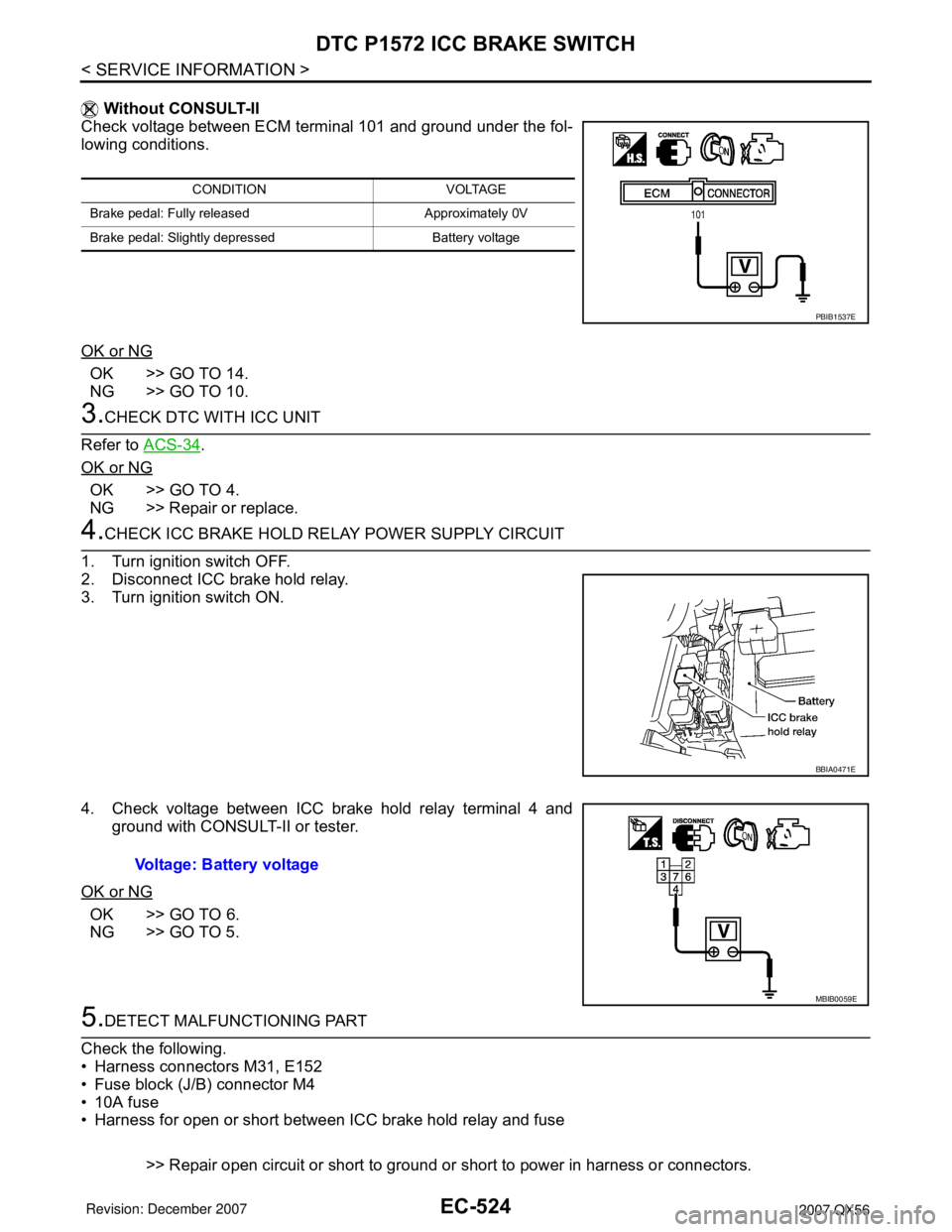
Without CONSULT-II
Check voltage between ECM terminal 101 and ground under the fol-
lowing conditions.
OK or NG
OK >> GO TO 14.
NG >> GO TO 10.
3.CHECK DTC WITH ICC UNIT
Refer to ACS-34
.
OK or NG
OK >> GO TO 4.
NG >> Repair or replace.
4.CHECK ICC BRAKE HOLD RELAY POWER SUPPLY CIRCUIT
1. Turn ignition switch OFF.
2. Disconnect ICC brake hold relay.
3. Turn ignition switch ON.
4. Check voltage between ICC brake hold relay terminal 4 and
ground with CONSULT-II or tester.
OK or NG
OK >> GO TO 6.
NG >> GO TO 5.
5.DETECT MALFUNCTIONING PART
Check the following.
• Harness connectors M31, E152
• Fuse block (J/B) connector M4
• 10A fuse
• Harness for open or short between ICC brake hold relay and fuse
>> Repair open circuit or short to ground or short to power in harness or connectors.
CONDITION VOLTAGE
Brake pedal: Fully released Approximately 0V
Brake pedal: Slightly depressed Battery voltage
PBIB1537E
BBIA0471E
Voltage: Battery voltage
MBIB0059E
Page 1609 of 3061
EC-526
< SERVICE INFORMATION >
DTC P1572 ICC BRAKE SWITCH
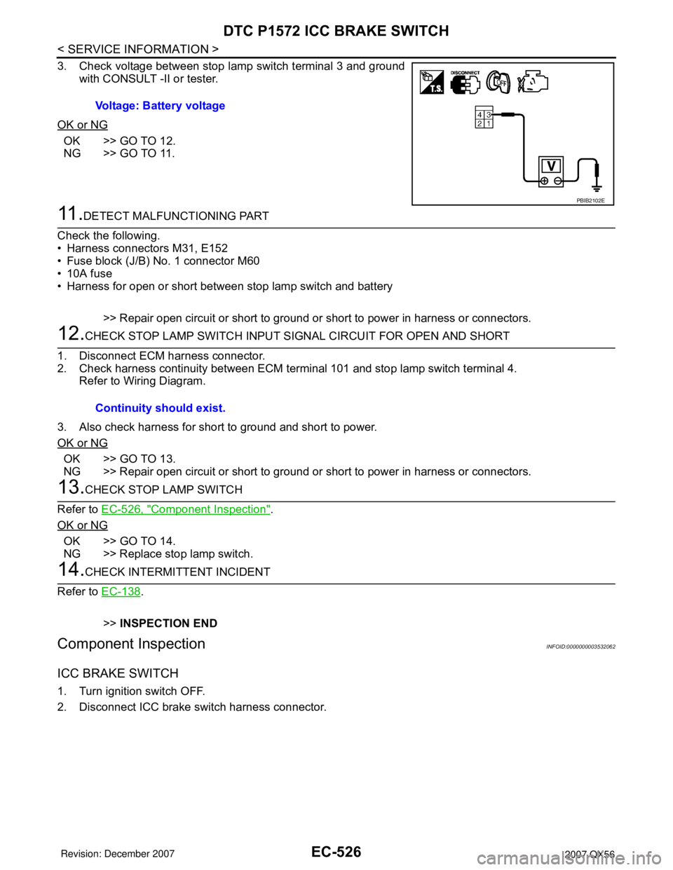
3. Check voltage between stop lamp switch terminal 3 and ground
with CONSULT -II or tester.
OK or NG
OK >> GO TO 12.
NG >> GO TO 11.
11 .DETECT MALFUNCTIONING PART
Check the following.
• Harness connectors M31, E152
• Fuse block (J/B) No. 1 connector M60
• 10A fuse
• Harness for open or short between stop lamp switch and battery
>> Repair open circuit or short to ground or short to power in harness or connectors.
12.CHECK STOP LAMP SWITCH INPUT SIGNAL CIRCUIT FOR OPEN AND SHORT
1. Disconnect ECM harness connector.
2. Check harness continuity between ECM terminal 101 and stop lamp switch terminal 4.
Refer to Wiring Diagram.
3. Also check harness for short to ground and short to power.
OK or NG
OK >> GO TO 13.
NG >> Repair open circuit or short to ground or short to power in harness or connectors.
13.CHECK STOP LAMP SWITCH
Refer to EC-526, "
Component Inspection".
OK or NG
OK >> GO TO 14.
NG >> Replace stop lamp switch.
14.CHECK INTERMITTENT INCIDENT
Refer to EC-138
.
>>INSPECTION END
Component InspectionINFOID:0000000003532062
ICC BRAKE SWITCH
1. Turn ignition switch OFF.
2. Disconnect ICC brake switch harness connector.Voltage: Battery voltage
PBIB2102E
Continuity should exist.
Page 1616 of 3061

DTC P1572 ASCD BRAKE SWITCH
EC-533
< SERVICE INFORMATION >
C
D
E
F
G
H
I
J
K
L
MA
EC
N
P O
• Harness connectors M31, E152
• Fuse block (J/B) connector M4
• 10A fuse
• Harness for open or short between ASCD brake switch and fuse
>> Repair open circuit or short to ground or short to power in harness or connectors.
5.CHECK ASCD BRAKE SWITCH INPUT SIGNAL CIRCUIT FOR OPEN AND SHORT
1. Turn ignition switch OFF.
2. Disconnect ECM harness connector.
3. Check harness continuity between ECM terminal 108 and ASCD brake switch terminal 2.
Refer to Wiring Diagram.
4. Also check harness for short to ground and short to power.
OK or NG
OK >> GO TO 6.
NG >> Repair open circuit or short to ground or short to power in harness or connectors.
6.CHECK ASCD BRAKE SWITCH
Refer to EC-534, "
Component Inspection".
OK or NG
OK >> GO TO 11.
NG >> Replace ASCD brake switch.
7.CHECK STOP LAMP SWITCH POWER SUPPLY CIRCUIT
1. Turn ignition switch OFF.
2. Disconnect stop lamp switch harness connector.
3. Check voltage between stop lamp switch terminal 3 and ground
with CONSULT-II or tester.
OK or NG
OK >> GO TO 9.
NG >> GO TO 8.
8.DETECT MALFUNCTIONING PART
Check the following.
• Harness connectors M31, E152
• Fuse block (J/B) connector M60
• 10A fuse
• Harness for open or short between stop lamp switch and batteryContinuity should exist.
BBIA0373E
Voltage: Battery voltage
PBIB2102E
Page 1624 of 3061
DTC P1805 BRAKE SWITCH
EC-541
< SERVICE INFORMATION >
C
D
E
F
G
H
I
J
K
L
MA
EC
N
P O
Diagnosis ProcedureINFOID:0000000003532083
1.CHECK STOP LAMP SWITCH CIRCUIT
1. Turn ignition switch OFF.
2. Check the stop lamp when depressing and releasing the brake pedal.
OK or NG
OK >> GO TO 4.
NG >> GO TO 2.
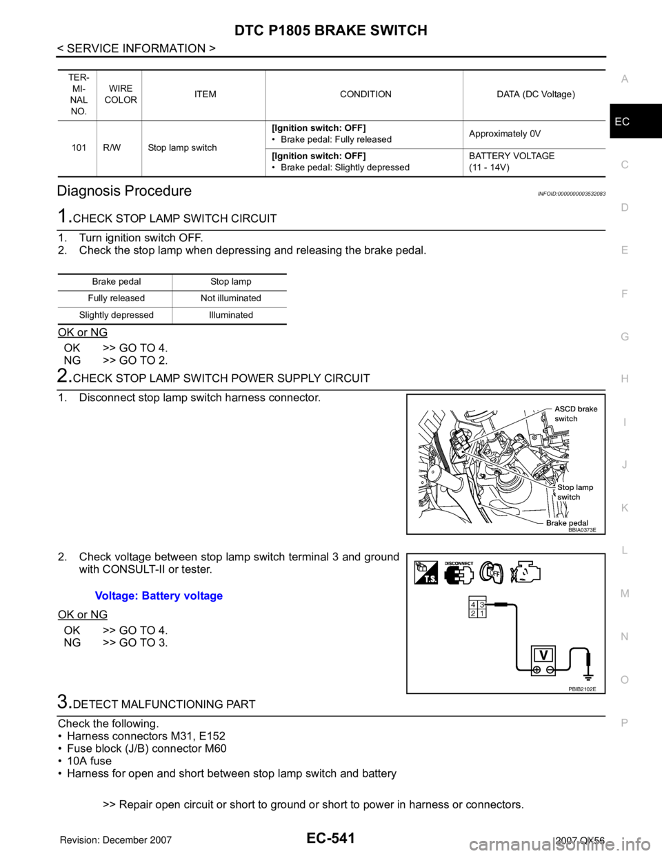
2.CHECK STOP LAMP SWITCH POWER SUPPLY CIRCUIT
1. Disconnect stop lamp switch harness connector.
2. Check voltage between stop lamp switch terminal 3 and ground
with CONSULT-II or tester.
OK or NG
OK >> GO TO 4.
NG >> GO TO 3.
3.DETECT MALFUNCTIONING PART
Check the following.
• Harness connectors M31, E152
• Fuse block (J/B) connector M60
• 10A fuse
• Harness for open and short between stop lamp switch and battery
>> Repair open circuit or short to ground or short to power in harness or connectors.
TER-
MI-
NAL
NO.WIRE
COLORITEM CONDITION DATA (DC Voltage)
101 R/W Stop lamp switch[Ignition switch: OFF]
• Brake pedal: Fully releasedApproximately 0V
[Ignition switch: OFF]
• Brake pedal: Slightly depressedBATTERY VOLTAGE
(11 - 14V)
Brake pedal Stop lamp
Fully released Not illuminated
Slightly depressed Illuminated
BBIA0373E
Voltage: Battery voltage
PBIB2102E
Page 1684 of 3061
ASCD BRAKE SWITCH
EC-601
< SERVICE INFORMATION >
C
D
E
F
G
H
I
J
K
L
MA
EC
N
P O
• Harness connectors M31, E152
• Fuse block (J/B) connector M4
• 10A fuse
• Harness for open or short between ASCD brake switch and fuse
>> Repair open circuit or short to ground or short to power in harness or connectors.
5.CHECK ASCD BRAKE SWITCH INPUT SIGNAL CIRCUIT FOR OPEN AND SHORT
1. Turn ignition switch OFF.
2. Disconnect ECM harness connector.
3. Check harness continuity between ECM terminal 108 and ASCD brake switch terminal 2.
Refer to Wiring Diagram.
4. Also check harness for short to ground and short to power.
OK or NG
OK >> GO TO 6.
NG >> Repair open circuit or short to ground or short to power in harness or connectors.
6.CHECK ASCD BRAKE SWITCH
Refer to EC-602, "
Component Inspection" .
OK or NG
OK >> GO TO 11.
NG >> Replace ASCD brake switch.
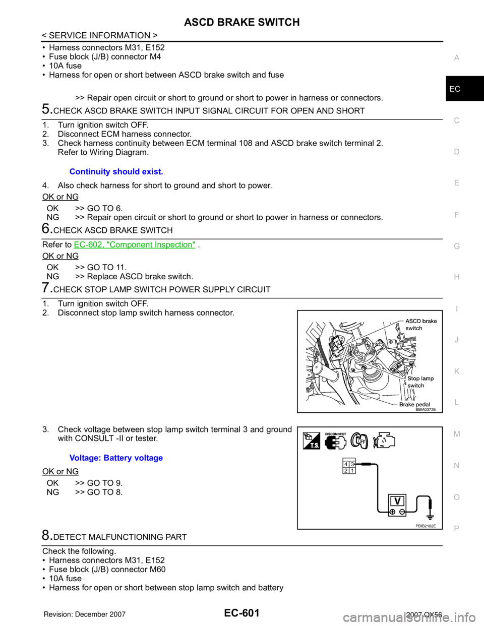
7.CHECK STOP LAMP SWITCH POWER SUPPLY CIRCUIT
1. Turn ignition switch OFF.
2. Disconnect stop lamp switch harness connector.
3. Check voltage between stop lamp switch terminal 3 and ground
with CONSULT -II or tester.
OK or NG
OK >> GO TO 9.
NG >> GO TO 8.
8.DETECT MALFUNCTIONING PART
Check the following.
• Harness connectors M31, E152
• Fuse block (J/B) connector M60
• 10A fuse
• Harness for open or short between stop lamp switch and batteryContinuity should exist.
BBIA0373E
Voltage: Battery voltage
PBIB2102E
Page 1705 of 3061
EC-622
< SERVICE INFORMATION >
ICC BRAKE SWITCH
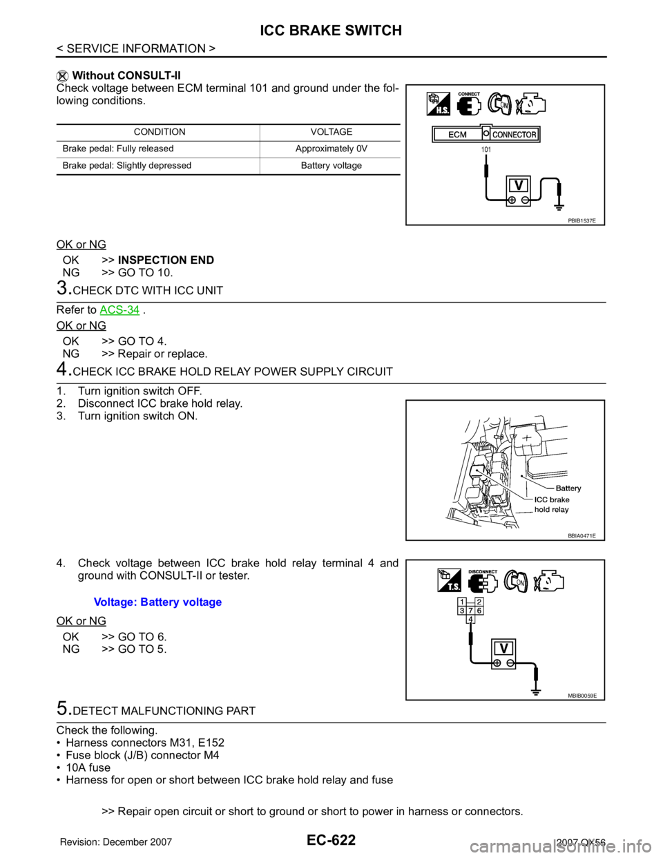
Without CONSULT-II
Check voltage between ECM terminal 101 and ground under the fol-
lowing conditions.
OK or NG
OK >>INSPECTION END
NG >> GO TO 10.
3.CHECK DTC WITH ICC UNIT
Refer to ACS-34
.
OK or NG
OK >> GO TO 4.
NG >> Repair or replace.
4.CHECK ICC BRAKE HOLD RELAY POWER SUPPLY CIRCUIT
1. Turn ignition switch OFF.
2. Disconnect ICC brake hold relay.
3. Turn ignition switch ON.
4. Check voltage between ICC brake hold relay terminal 4 and
ground with CONSULT-II or tester.
OK or NG
OK >> GO TO 6.
NG >> GO TO 5.
5.DETECT MALFUNCTIONING PART
Check the following.
• Harness connectors M31, E152
• Fuse block (J/B) connector M4
• 10A fuse
• Harness for open or short between ICC brake hold relay and fuse
>> Repair open circuit or short to ground or short to power in harness or connectors.
CONDITION VOLTAGE
Brake pedal: Fully released Approximately 0V
Brake pedal: Slightly depressed Battery voltage
PBIB1537E
BBIA0471E
Voltage: Battery voltage
MBIB0059E
Page 1707 of 3061
EC-624
< SERVICE INFORMATION >
ICC BRAKE SWITCH
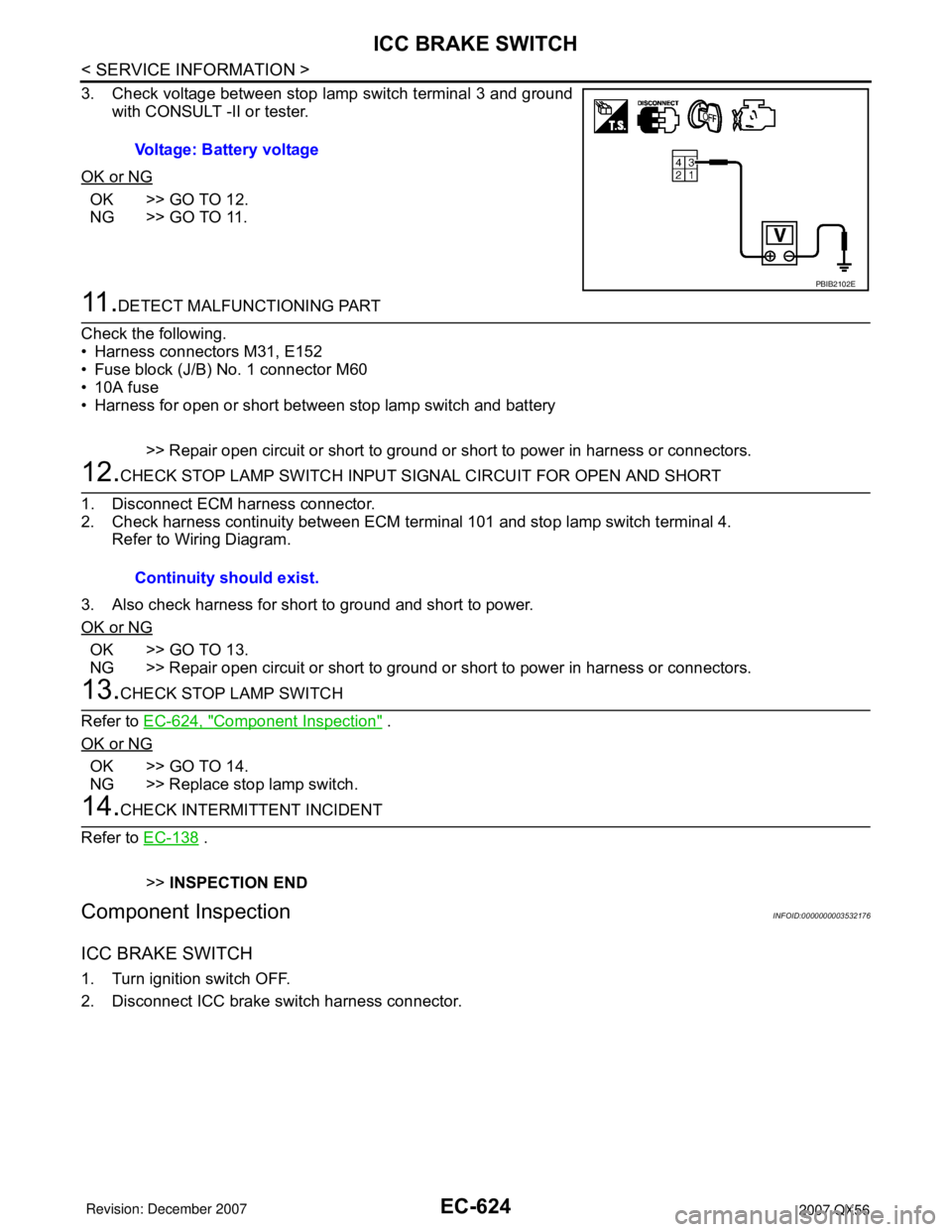
3. Check voltage between stop lamp switch terminal 3 and ground
with CONSULT -II or tester.
OK or NG
OK >> GO TO 12.
NG >> GO TO 11.
11 .DETECT MALFUNCTIONING PART
Check the following.
• Harness connectors M31, E152
• Fuse block (J/B) No. 1 connector M60
• 10A fuse
• Harness for open or short between stop lamp switch and battery
>> Repair open circuit or short to ground or short to power in harness or connectors.
12.CHECK STOP LAMP SWITCH INPUT SIGNAL CIRCUIT FOR OPEN AND SHORT
1. Disconnect ECM harness connector.
2. Check harness continuity between ECM terminal 101 and stop lamp switch terminal 4.
Refer to Wiring Diagram.
3. Also check harness for short to ground and short to power.
OK or NG
OK >> GO TO 13.
NG >> Repair open circuit or short to ground or short to power in harness or connectors.
13.CHECK STOP LAMP SWITCH
Refer to EC-624, "
Component Inspection" .
OK or NG
OK >> GO TO 14.
NG >> Replace stop lamp switch.
14.CHECK INTERMITTENT INCIDENT
Refer to EC-138
.
>>INSPECTION END
Component InspectionINFOID:0000000003532176
ICC BRAKE SWITCH
1. Turn ignition switch OFF.
2. Disconnect ICC brake switch harness connector.Voltage: Battery voltage
PBIB2102E
Continuity should exist.