2007 INFINITI QX56 fuel tank removal
[x] Cancel search: fuel tank removalPage 1030 of 3061
COMBINATION METERSDI-19
< SERVICE INFORMATION >
C
DE
F
G H
I
J
L
M A
B
DI
N
O P
• Depending on vehicle position or driving circumstance, the fuel in the tank shifts and the indication may fluc-
tuate.
• If the vehicle is fueled with the ignition switch ON, the indication will update slowly.
• If the vehicle is tilted when the ignition switch is turned ON, fuel in the tank may flow to one direction result-
ing in a change of reading.
LOW-FUEL WARNING LAMP
Depending on vehicle posture or driving circumstances, the fuel level in the tank varies, and the warning lamp
ON timing may be changed.
1.CHECK SELF-DIAGNOSIS
Perform the combination meter self-diagnosis. Refer to DI-12, "
Self-Diagnosis Mode of Combination Meter".
OK or NG
OK >> GO TO 2.
NG >> Replace the combination meter. Refer to IP-10, "
Removal and Installation".
2.CHECK HARNESS CONNECTOR
1. Turn the ignition switch OFF.
2. Check combination meter and fuel level sensor unit and fuel pump terminals (meter-side, and harness-
side) for poor connection.
OK or NG
OK >> GO TO 3.
NG >> Repair or replace terminals or connectors.
3.CHECK HARNESS CONNECTOR OUTPUT SIGNAL
1. Disconnect fuel level sensor unit and fuel pump connector.
2. Turn ignition switch ON.
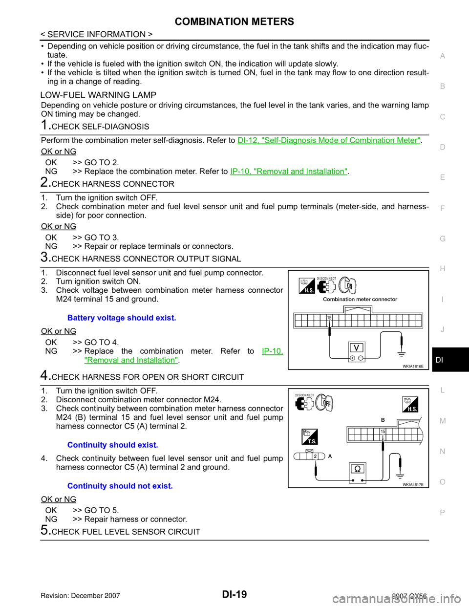
3. Check voltage between combination meter harness connector M24 terminal 15 and ground.
OK or NG
OK >> GO TO 4.
NG >> Replace the combination meter. Refer to IP-10,
"Removal and Installation".
4.CHECK HARNESS FOR OPEN OR SHORT CIRCUIT
1. Turn the ignition switch OFF.
2. Disconnect combination meter connector M24.
3. Check continuity between combination meter harness connector M24 (B) terminal 15 and fuel level sensor unit and fuel pump
harness connector C5 (A) terminal 2.
4. Check continuity between fuel level sensor unit and fuel pump harness connector C5 (A) terminal 2 and ground.
OK or NG
OK >> GO TO 5.
NG >> Repair harness or connector.
5.CHECK FUEL LEVEL SENSOR CIRCUIT Battery voltage should exist.
WKIA1816E
Continuity should exist.
Continuity should not exist.
WKIA4617E
Page 1031 of 3061
DI-20
< SERVICE INFORMATION >
COMBINATION METERS
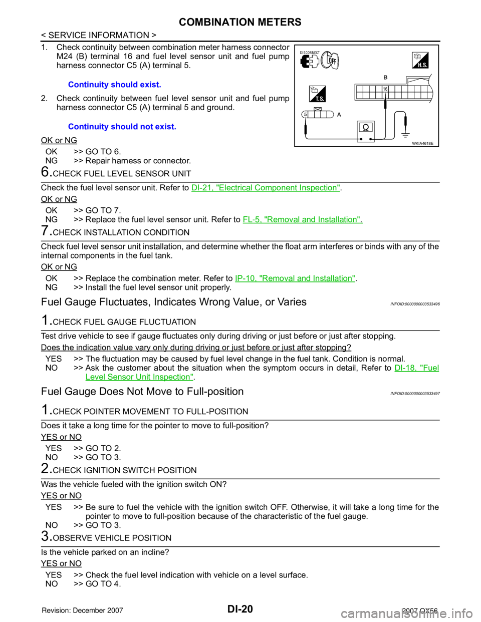
1. Check continuity between combination meter harness connectorM24 (B) terminal 16 and fuel level sensor unit and fuel pump
harness connector C5 (A) terminal 5.
2. Check continuity between fuel level sensor unit and fuel pump harness connector C5 (A) terminal 5 and ground.
OK or NG
OK >> GO TO 6.
NG >> Repair harness or connector.
6.CHECK FUEL LEVEL SENSOR UNIT
Check the fuel level sensor unit. Refer to DI-21, "
Electrical Component Inspection".
OK or NG
OK >> GO TO 7.
NG >> Replace the fuel level sensor unit. Refer to FL-5, "
Removal and Installation".
7.CHECK INSTALLATION CONDITION
Check fuel level sensor unit installation, and determine whet her the float arm interferes or binds with any of the
internal components in the fuel tank.
OK or NG
OK >> Replace the combination meter. Refer to IP-10, "Removal and Installation".
NG >> Install the fuel level sensor unit properly.
Fuel Gauge Fluctuat es, Indicates Wrong Value, or VariesINFOID:0000000003533496
1.CHECK FUEL GAUGE FLUCTUATION
Test drive vehicle to see if gauge fluctuates only during driving or just before or just after stopping.
Does the indication value vary only during driving or just before or just after stopping?
YES >> The fluctuation may be caused by fuel leve l change in the fuel tank. Condition is normal.
NO >> Ask the customer about the situation when the symptom occurs in detail, Refer to DI-18, "
Fuel
Level Sensor Unit Inspection".
Fuel Gauge Does Not Move to Full-positionINFOID:0000000003533497
1.CHECK POINTER MOVEME NT TO FULL-POSITION
Does it take a long time for the pointer to move to full-position?
YES or NO
YES >> GO TO 2.
NO >> GO TO 3.
2.CHECK IGNITION SWITCH POSITION
Was the vehicle fueled with the ignition switch ON?
YES or NO
YES >> Be sure to fuel the vehicle with the ignition s witch OFF. Otherwise, it will take a long time for the
pointer to move to full-position because of the characteristic of the fuel gauge.
NO >> GO TO 3.
3.OBSERVE VEHICLE POSITION
Is the vehicle parked on an incline?
YES or NO
YES >> Check the fuel level indication with vehicle on a level surface.
NO >> GO TO 4. Continuity should exist.
Continuity should not exist.
WKIA4618E
Page 1032 of 3061
COMBINATION METERS
DI-21
< SERVICE INFORMATION >
C
D
E
F
G
H
I
J
L
MA
B
DI
N
O
P
4.CHECK POINTER MOVEMENT TO EMPTY-POSITION
During driving, does the fuel gauge move gradually toward empty-position?
YES or NO
YES >> Check the fuel level sensor unit. Refer to DI-21, "Electrical Component Inspection".
NO >> Check fuel level sensor unit installation, and determine whether the float arm interferes or binds
with any of the internal components in the fuel tank.
Electrical Component InspectionINFOID:0000000003533498
FUEL LEVEL SENSOR UNIT CHECK
For removal, refer to FL-5, "Removal and Installation".
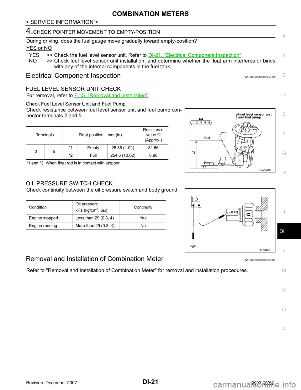
Check Fuel Level Sensor Unit and Fuel Pump
Check resistance between fuel level sensor unit and fuel pump con-
nector terminals 2 and 5.
*1 and *2: When float rod is in contact with stopper.
OIL PRESSURE SWITCH CHECK
Check continuity between the oil pressure switch and body ground.
Removal and Installation of Combination MeterINFOID:0000000003533499
Refer to "Removal and Installation of Combination Meter" for removal and installation procedures.
Terminals Float position mm (in)Resistance
value Ω
(Approx.)
25*1 Empty 25.86 (1.02) 81.66
*2 Full 254.6 (10.02) 6.98
LKIA0402E
ConditionOil pressure
kPa (kg/cm2, psi)Continuity
Engine stopped Less than 29 (0.3, 4) Yes
Engine running More than 29 (0.3, 4) No
ELF0044D
Page 1396 of 3061
DTC P0181 FTT SENSOR
EC-313
< SERVICE INFORMATION >
C
D
E
F
G
H
I
J
K
L
MA
EC
N
P O
NG >> Replace “fuel level sensor unit and fuel pump”.
6.CHECK INTERMITTENT INCIDENT
Refer to EC-138
.
>>INSPECTION END
Component InspectionINFOID:0000000003531805
FUEL TANK TEMPERATURE SENSOR
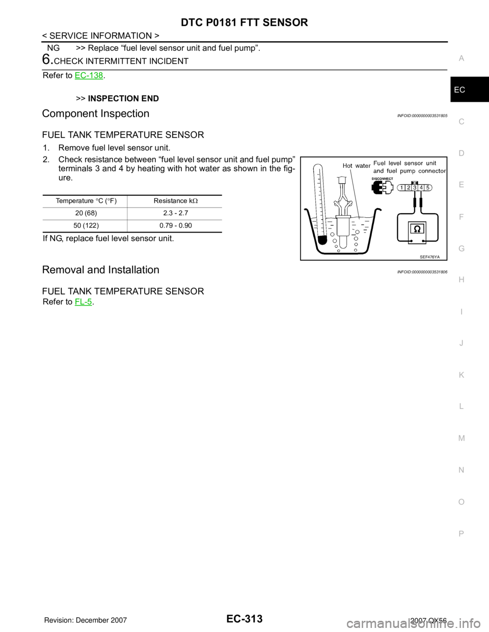
1. Remove fuel level sensor unit.
2. Check resistance between “fuel level sensor unit and fuel pump”
terminals 3 and 4 by heating with hot water as shown in the fig-
ure.
If NG, replace fuel level sensor unit.
Removal and InstallationINFOID:0000000003531806
FUEL TANK TEMPERATURE SENSOR
Refer to FL-5.
Temperature °C (°F) Resistance kΩ
20 (68) 2.3 - 2.7
50 (122) 0.79 - 0.90
SEF476YA
Page 1400 of 3061
DTC P0182, P0183 FTT SENSOR
EC-317
< SERVICE INFORMATION >
C
D
E
F
G
H
I
J
K
L
MA
EC
N
P O
>>INSPECTION END
Component InspectionINFOID:0000000003531812
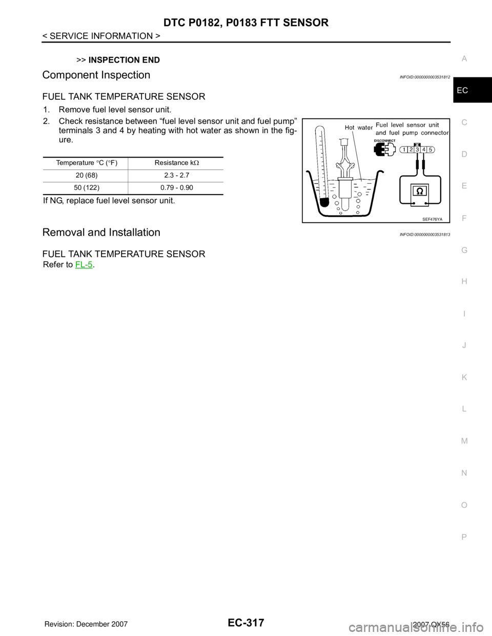
FUEL TANK TEMPERATURE SENSOR
1. Remove fuel level sensor unit.
2. Check resistance between “fuel level sensor unit and fuel pump”
terminals 3 and 4 by heating with hot water as shown in the fig-
ure.
If NG, replace fuel level sensor unit.
Removal and InstallationINFOID:0000000003531813
FUEL TANK TEMPERATURE SENSOR
Refer to FL-5.
Temperature °C (°F) Resistance kΩ
20 (68) 2.3 - 2.7
50 (122) 0.79 - 0.90
SEF476YA
Page 1493 of 3061
EC-410
< SERVICE INFORMATION >
DTC P0455 EVAP CONTROL SYSTEM
Diagnosis Procedure
INFOID:0000000003531911
1.CHECK FUEL FILLER CAP DESIGN
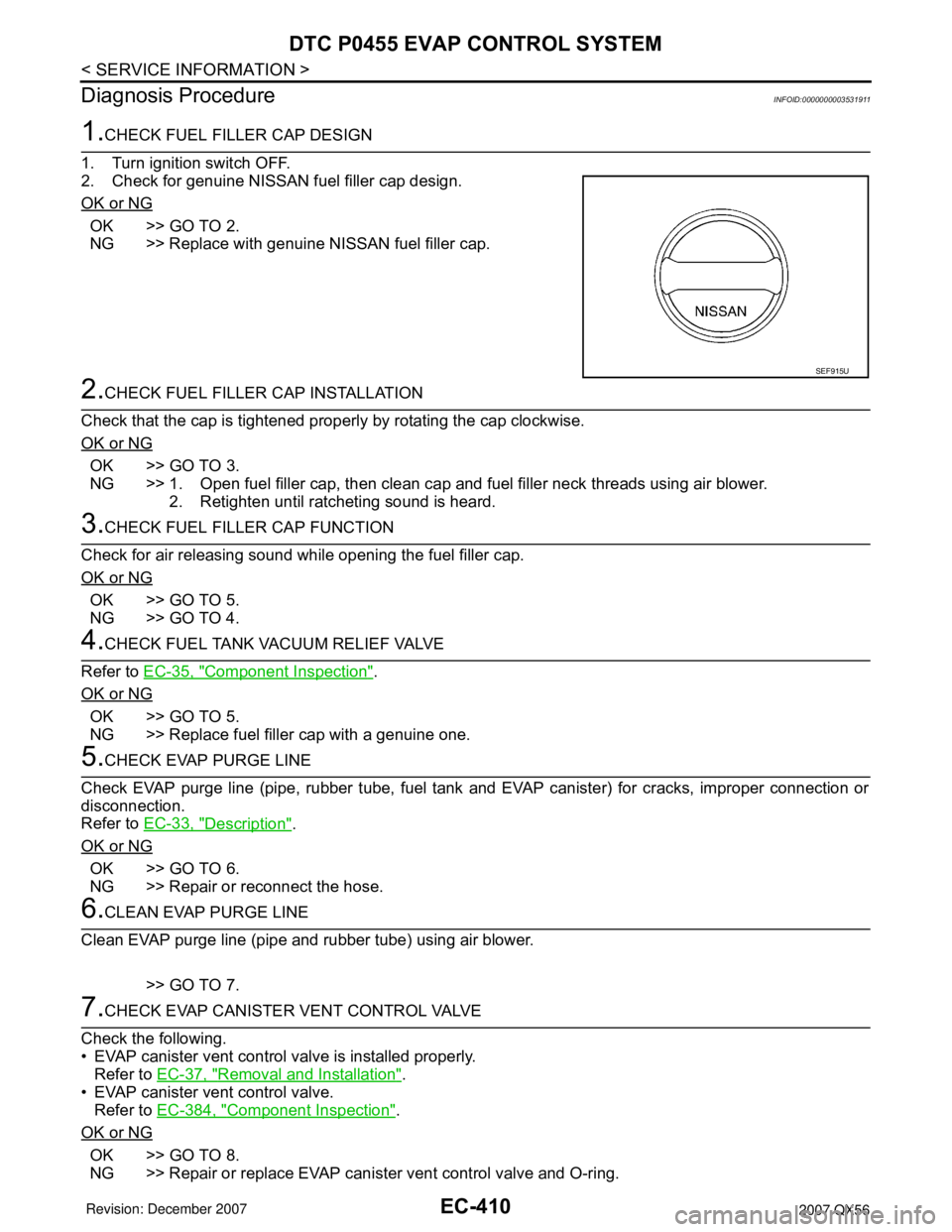
1. Turn ignition switch OFF.
2. Check for genuine NISSAN fuel filler cap design.
OK or NG
OK >> GO TO 2.
NG >> Replace with genuine NISSAN fuel filler cap.
2.CHECK FUEL FILLER CAP INSTALLATION
Check that the cap is tightened properly by rotating the cap clockwise.
OK or NG
OK >> GO TO 3.
NG >> 1. Open fuel filler cap, then clean cap and fuel filler neck threads using air blower.
2. Retighten until ratcheting sound is heard.
3.CHECK FUEL FILLER CAP FUNCTION
Check for air releasing sound while opening the fuel filler cap.
OK or NG
OK >> GO TO 5.
NG >> GO TO 4.
4.CHECK FUEL TANK VACUUM RELIEF VALVE
Refer to EC-35, "
Component Inspection".
OK or NG
OK >> GO TO 5.
NG >> Replace fuel filler cap with a genuine one.
5.CHECK EVAP PURGE LINE
Check EVAP purge line (pipe, rubber tube, fuel tank and EVAP canister) for cracks, improper connection or
disconnection.
Refer to EC-33, "
Description".
OK or NG
OK >> GO TO 6.
NG >> Repair or reconnect the hose.
6.CLEAN EVAP PURGE LINE
Clean EVAP purge line (pipe and rubber tube) using air blower.
>> GO TO 7.
7.CHECK EVAP CANISTER VENT CONTROL VALVE
Check the following.
• EVAP canister vent control valve is installed properly.
Refer to EC-37, "
Removal and Installation".
• EVAP canister vent control valve.
Refer to EC-384, "
Component Inspection".
OK or NG
OK >> GO TO 8.
NG >> Repair or replace EVAP canister vent control valve and O-ring.
SEF915U
Page 1509 of 3061
EC-426
< SERVICE INFORMATION >
DTC P0461 FUEL LEVEL SENSOR
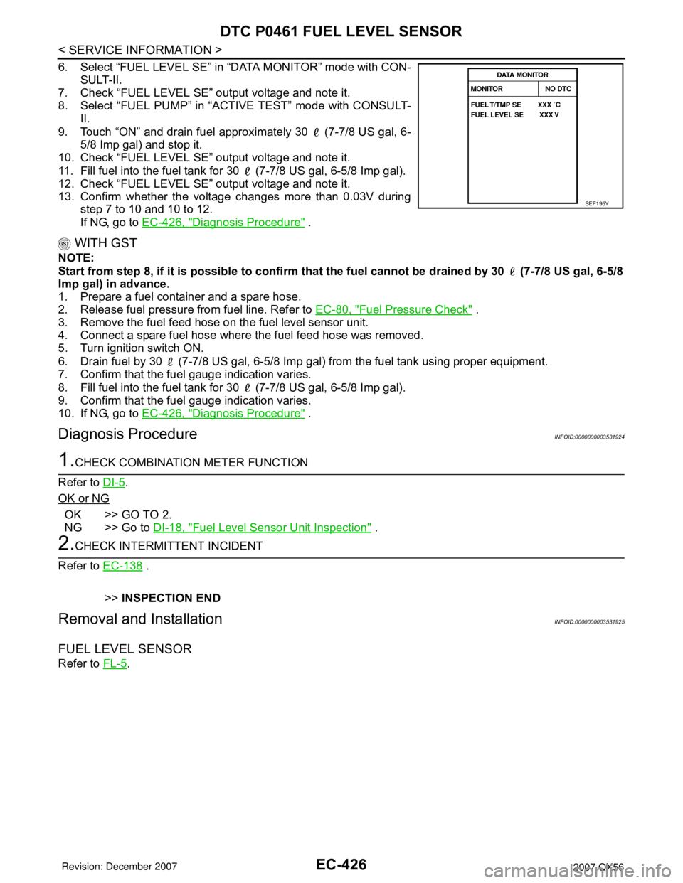
6. Select “FUEL LEVEL SE” in “DATA MONITOR” mode with CON-
SULT-II.
7. Check “FUEL LEVEL SE” output voltage and note it.
8. Select “FUEL PUMP” in “ACTIVE TEST” mode with CONSULT-
II.
9. Touch “ON” and drain fuel approximately 30 (7-7/8 US gal, 6-
5/8 Imp gal) and stop it.
10. Check “FUEL LEVEL SE” output voltage and note it.
11. Fill fuel into the fuel tank for 30 (7-7/8 US gal, 6-5/8 Imp gal).
12. Check “FUEL LEVEL SE” output voltage and note it.
13. Confirm whether the voltage changes more than 0.03V during
step 7 to 10 and 10 to 12.
If NG, go to EC-426, "
Diagnosis Procedure" .
WITH GST
NOTE:
Start from step 8, if it is possible to confirm that the fuel cannot be drained by 30 (7-7/8 US gal, 6-5/8
Imp gal) in advance.
1. Prepare a fuel container and a spare hose.
2. Release fuel pressure from fuel line. Refer to EC-80, "
Fuel Pressure Check" .
3. Remove the fuel feed hose on the fuel level sensor unit.
4. Connect a spare fuel hose where the fuel feed hose was removed.
5. Turn ignition switch ON.
6. Drain fuel by 30 (7-7/8 US gal, 6-5/8 Imp gal) from the fuel tank using proper equipment.
7. Confirm that the fuel gauge indication varies.
8. Fill fuel into the fuel tank for 30 (7-7/8 US gal, 6-5/8 Imp gal).
9. Confirm that the fuel gauge indication varies.
10. If NG, go to EC-426, "
Diagnosis Procedure" .
Diagnosis ProcedureINFOID:0000000003531924
1.CHECK COMBINATION METER FUNCTION
Refer to DI-5
.
OK or NG
OK >> GO TO 2.
NG >> Go to DI-18, "
Fuel Level Sensor Unit Inspection" .
2.CHECK INTERMITTENT INCIDENT
Refer to EC-138
.
>>INSPECTION END
Removal and InstallationINFOID:0000000003531925
FUEL LEVEL SENSOR
Refer to FL-5.
SEF195Y
Page 1845 of 3061
ENGINE ASSEMBLY
EM-75
< SERVICE INFORMATION >
C
D
E
F
G
H
I
J
K
L
MA
EM
N
P O
6. Remove the engine room cover using power tools.
7. Remove the air duct and air cleaner case assembly. Refer to EM-15, "
Removal and Installation".
8. Disconnect the vacuum hose between the vehicle and engine and set it aside.
9. Remove the radiator assembly and hoses. Refer to CO-13, "
Removal and Installation".
10. Remove the drive belts. Refer to EM-15, "
Removal and Installation".
11. Remove the fan blade. Refer to CO-16, "
Removal and Installation (Crankshaft Driven Type)".
12. Disconnect the engine room harness from the fuse box and set it aside.
13. Disconnect the ECM.
14. Disconnect the engine room harness from the engine side and set it aside.
15. Disconnect the engine harness grounds.
16. Disconnect the power steering reservoir tank from the engine and move it aside.
17. Disconnect the power steering oil pump from the engine. Move it aside and secure it using suitable wire or
rope. Refer to PS-21, "
Removal and Installation".
18. Remove the A/C compressor bolts and set the compressor aside. Refer to ATC-154, "
Removal and Instal-
lation for Compressor" (ATC).
19. Disconnect the brake booster vacuum line.
20. Disconnect the EVAP line.
21. Disconnect the fuel hose at the engine side connection. Refer to EM-31, "
Removal and Installation".
22. Disconnect the heater hoses at the cowl, and install plugs to avoid leakage of engine coolant.
23. Remove the A/T oil level indicator and indicator tube upper bolts.
24. Remove the front final drive assembly (4WD only). Refer to FFD-12, "
Removal and Installation".
25. Remove the exhaust manifolds. Refer to EM-21, "
Removal and Installation".
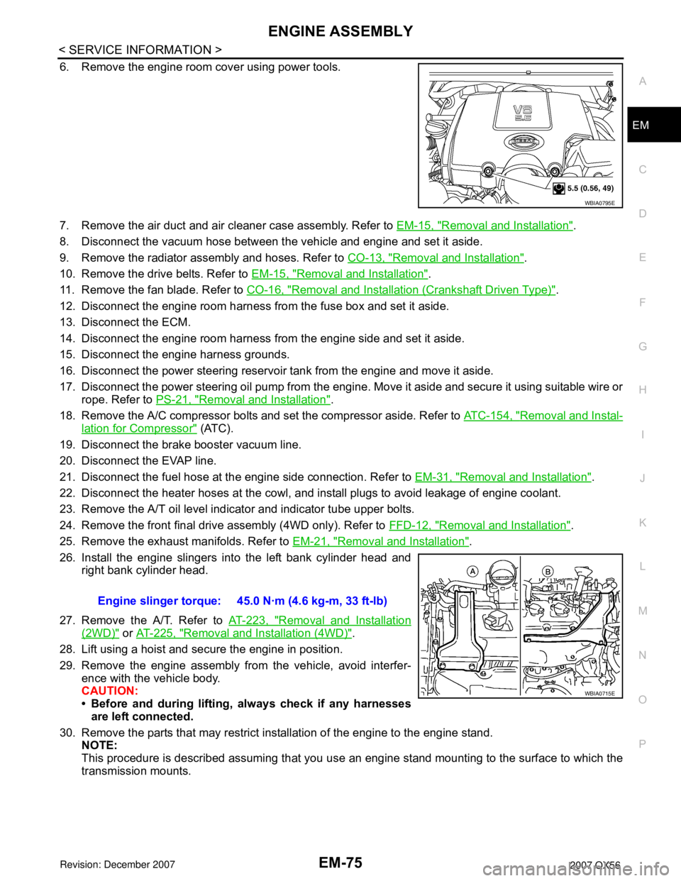
26. Install the engine slingers into the left bank cylinder head and
right bank cylinder head.
27. Remove the A/T. Refer to AT-223, "
Removal and Installation
(2WD)" or AT-225, "Removal and Installation (4WD)".
28. Lift using a hoist and secure the engine in position.
29. Remove the engine assembly from the vehicle, avoid interfer-
ence with the vehicle body.
CAUTION:
• Before and during lifting, always check if any harnesses
are left connected.
30. Remove the parts that may restrict installation of the engine to the engine stand.
NOTE:
This procedure is described assuming that you use an engine stand mounting to the surface to which the
transmission mounts.
WBIA0795E
Engine slinger torque: 45.0 N·m (4.6 kg-m, 33 ft-lb)
WBIA0715E