2007 INFINITI QX56 timing belt
[x] Cancel search: timing beltPage 540 of 3061

ATC-170
< SERVICE INFORMATION >
SERVICE DATA AND SPECIFICATIONS (SDS)
SERVICE DATA AND SPECIFICATIONS (SDS)
Service Data and Specification (SDS)INFOID:0000000003533311
COMPRESSOR
OIL
REFRIGERANT
ENGINE IDLING SPEED
Refer to EC-75, "Idle Speed and Ignition Timing Check".
BELT TENSION
Refer to EM-13, "Checking Drive Belts".
Make ZEXEL VALEO CLIMATE CONTROL
Model DKS-17D
Ty p e Swash plate
Displacement 175.5 cm
3 (10.7 in3 ) / revolution
Cylinder bore × stroke 30.5 mm (1.20 in) x 24.0 mm (0.94 in)
Direction of rotation Clockwise (viewed from drive end)
Drive belt Poly V
Name NISSAN A/C System Oil Type S
Capacity 290 m (9.8 US fl oz, 10.2 Imp fl oz)
Ty p eHFC 134a (R-134a)
Capacity 1.08 ± 0.05 kg (2.38 ± 0.11 oz)
Page 929 of 3061

BRC-1
BRAKES
C
D
E
G
H
I
J
K
L
M
SECTION BRC
A
B
BRC
N
O
P
CONTENTS
BRAKE CONTROL SYSTEM
VDC/TCS/ABS
SERVICE INFORMATION ............................
3
PRECAUTIONS ...................................................3
Precaution for Supplemental Restraint System
(SRS) "AIR BAG" and "SEAT BELT PRE-TEN-
SIONER" ...................................................................
3
Precaution for Brake System ....................................3
Precaution When Using CONSULT-II .......................3
Precaution for Brake Control .....................................4
Precaution for CAN System ......................................4
PREPARATION ...................................................6
Special Service Tool .................................................6
Commercial Service Tool ..........................................6
SYSTEM DESCRIPTION .....................................7
System Component ...................................................7
ABS Function ............................................................8
EBD Function ............................................................8
TCS Function ............................................................8
VDC Function ............................................................8
Fail-Safe Function .....................................................8
Hydraulic Circuit Diagram .........................................9
CAN COMMUNICATION ....................................10
System Description .................................................10
TROUBLE DIAGNOSIS .....................................11
How to Perform Trouble Diagnosis for Quick and
Accurate Repair ......................................................
11
Component Parts and Harness Connector Loca-
tion ..........................................................................
14
Schematic ...............................................................15
Wiring Diagram - VDC - ..........................................16
Basic Inspection ......................................................22
Warning Lamp and Indicator Timing .......................23
Control Unit Input/Output Signal Standard ..............23
CONSULT-II Function (ABS) ..................................26
TROUBLE DIAGNOSIS FOR SELF-DIAG-
NOSTIC ITEMS .................................................
34
Wheel Sensor System Inspection ............................34
Engine System Inspection .......................................35
ABS/TCS/VDC Control Unit Inspection ...................35
Steering Angle Sensor System ................................36
Yaw Rate/Side/Decel G Sensor System Inspec-
tion ...........................................................................
37
Solenoid and VDC Change-Over Valve System
Inspection ................................................................
38
Actuator Motor, Motor Relay, and Circuit Inspec-
tion ...........................................................................
39
Stop Lamp Switch System Inspection .....................40
ABS/TCS/VDC Control Unit Power and Ground
Systems Inspection .................................................
41
Brake Fluid Level Switch System Inspection ...........42
Active Booster System Inspection ...........................43
Delta Stroke Sensor System Inspection ..................44
Pressure Sensor System Inspection .......................45
Steering Angle Sensor Safe Mode Inspection .........47
CAN Communication System Inspection .................48
ICC System Inspection ............................................48
Inspection for Self-Diagnosis Result "ST ANG
SEN SIGNAL" ..........................................................
48
Inspection for Self-Diagnosis Result "DECEL G
SEN SET" ................................................................
49
TROUBLE DIAGNOSES FOR SYMPTOMS .....50
ABS Works Frequently ............................................50
Unexpected Pedal Action ........................................50
Long Stopping Distance ..........................................51
ABS Does Not Work ................................................51
Pedal Vibration or ABS Operation Noise .................51
Vehicle Jerks During TCS/VDC Activation ..............52
Component Inspection .............................................53
ON-VEHICLE SERVICE ....................................54
Adjustment of Steering Angle Sensor Neutral Po-
sition ........................................................................
54
Calibration of Decel G Sensor .................................54
Page 1084 of 3061

EC-1
ENGINE
C
D
E
F
G
H
I
J
K
L
M
SECTION EC
A
EC
N
O
P
CONTENTS
ENGINE CONTROL SYSTEM
SERVICE INFORMATION ............................9
INDEX FOR DTC .................................................9
DTC No. Index ..........................................................9
Alphabetical Index ...................................................12
PRECAUTIONS ..................................................17
Precaution for Supplemental Restraint System
(SRS) "AIR BAG" and "SEAT BELT PRE-TEN-
SIONER" .................................................................
17
On Board Diagnosis (OBD) System of Engine and
A/T ...........................................................................
17
Precaution ...............................................................17
PREPARATION ..................................................21
Special Service Tool ...............................................21
Commercial Service Tool ........................................22
ENGINE CONTROL SYSTEM ............................24
Schematic ...............................................................24
Multiport Fuel Injection (MFI) System .....................24
Electronic Ignition (EI) System ................................27
Fuel Cut Control (at No Load and High Engine
Speed) .....................................................................
27
AIR CONDITIONING CUT CONTROL ...............29
Input/Output Signal Chart ........................................29
System Description .................................................29
AUTOMATIC SPEED CONTROL DEVICE
(ASCD) ...............................................................
30
System Description .................................................30
Component Description ...........................................31
CAN COMMUNICATION ....................................32
System Description .................................................32
EVAPORATIVE EMISSION SYSTEM ................33
Description ..............................................................33
Component Inspection ............................................35
Removal and Installation .........................................37
How to Detect Fuel Vapor Leakage ........................37
ON BOARD REFUELING VAPOR RECOV-
ERY (ORVR) ......................................................
40
System Description ..................................................40
Diagnosis Procedure ...............................................40
Component Inspection .............................................42
POSITIVE CRANKCASE VENTILATION .........45
Description ...............................................................45
Component Inspection .............................................45
IVIS (INFINITI VEHICLE IMMOBILIZER SYS-
TEM-NATS) .......................................................
47
Description ...............................................................47
ON BOARD DIAGNOSTIC (OBD) SYSTEM ....48
Introduction ..............................................................48
Two Trip Detection Logic .........................................48
Emission-related Diagnostic Information .................49
Malfunction Indicator Lamp (MIL) ............................63
OBD System Operation Chart .................................65
BASIC SERVICE PROCEDURE .......................71
Basic Inspection ......................................................71
Idle Speed and Ignition Timing Check .....................75
Procedure After Replacing ECM .............................77
VIN Registration ......................................................77
Accelerator Pedal Released Position Learning .......77
Throttle Valve Closed Position Learning .................77
Idle Air Volume Learning .........................................78
Fuel Pressure Check ...............................................80
TROUBLE DIAGNOSIS ....................................82
Trouble Diagnosis Introduction ................................82
DTC Inspection Priority Chart ..................................87
Fail-Safe Chart ........................................................88
Symptom Matrix Chart .............................................90
Engine Control Component Parts Location .............94
Vacuum Hose Drawing ..........................................100
Circuit Diagram ......................................................101
ECM Harness Connector Terminal Layout ............103
ECM Terminal and Reference Value .....................103
Page 1180 of 3061

TROUBLE DIAGNOSIS
EC-97
< SERVICE INFORMATION >
C
D
E
F
G
H
I
J
K
L
MA
EC
N
P O
13. Intake valve timing control position
sensor (bank 1) (view with engine
cover and intake air duct removed)14. Intake valve timing control solenoid
valve (bank 2) (view with engine cov-
er and intake air duct removed)15. Drive belt (view with engine cover
and intake air duct removed)
16. Radiator hose (view with engine cov-
er and intake air duct removed)17. Intake valve timing control solenoid
valve (bank 1) (view with engine cov-
er and intake air duct removed)
1. Knock sensor (bank 1) (view with en-
gine removed)2. Knock sensor (bank 2) (view with en-
gine removed)3. Battery current sensor
4. Power steering pressure sensor 5. Power steering fluid reservoir 6. Intake manifold
7. Engine coolant temperature sensor 8. Ignition coils (with power transistor) 9. Ignition coil (with power transistor)
10. Injector harness connectors (bank 2) 11. Injector harness connectors (bank 1)
BBIA0774E
Page 1239 of 3061

EC-156
< SERVICE INFORMATION >
DTC P0011, P0021 IVT CONTROL
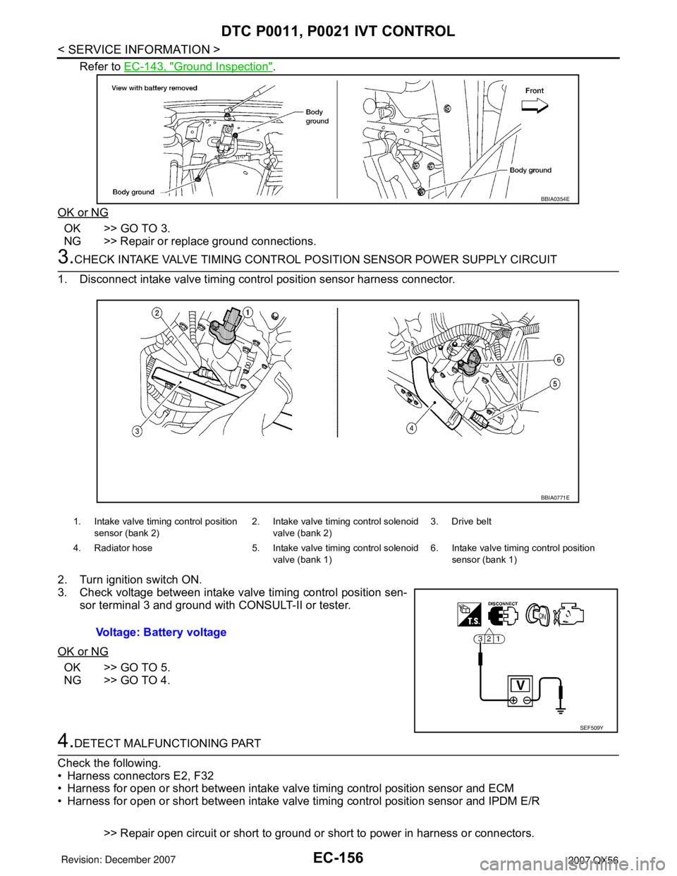
Refer to EC-143, "Ground Inspection".
OK or NG
OK >> GO TO 3.
NG >> Repair or replace ground connections.
3.CHECK INTAKE VALVE TIMING CONTROL POSITION SENSOR POWER SUPPLY CIRCUIT
1. Disconnect intake valve timing control position sensor harness connector.
2. Turn ignition switch ON.
3. Check voltage between intake valve timing control position sen-
sor terminal 3 and ground with CONSULT-II or tester.
OK or NG
OK >> GO TO 5.
NG >> GO TO 4.
4.DETECT MALFUNCTIONING PART
Check the following.
• Harness connectors E2, F32
• Harness for open or short between intake valve timing control position sensor and ECM
• Harness for open or short between intake valve timing control position sensor and IPDM E/R
>> Repair open circuit or short to ground or short to power in harness or connectors.
BBIA0354E
1. Intake valve timing control position
sensor (bank 2)2. Intake valve timing control solenoid
valve (bank 2)3. Drive belt
4. Radiator hose 5. Intake valve timing control solenoid
valve (bank 1)6. Intake valve timing control position
sensor (bank 1)
Voltage: Battery voltage
BBIA0771E
SEF509Y
Page 1241 of 3061

EC-158
< SERVICE INFORMATION >
DTC P0011, P0021 IVT CONTROL
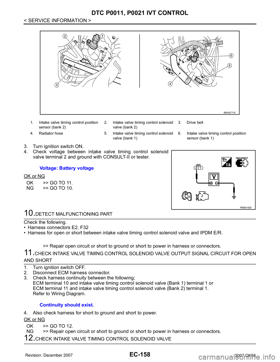
3. Turn ignition switch ON.
4. Check voltage between intake valve timing control solenoid
valve terminal 2 and ground with CONSULT-II or tester.
OK or NG
OK >> GO TO 11.
NG >> GO TO 10.
10.DETECT MALFUNCTIONING PART
Check the following.
• Harness connectors E2, F32
• Harness for open or short between intake valve timing control solenoid valve and IPDM E/R.
>> Repair open circuit or short to ground or short to power in harness or connectors.
11 .CHECK INTAKE VALVE TIMING CONTROL SOLENOID VALVE OUTPUT SIGNAL CIRCUIT FOR OPEN
AND SHORT
1. Turn ignition switch OFF.
2. Disconnect ECM harness connector.
3. Check harness continuity between the following;
ECM terminal 10 and intake valve timing control solenoid valve (Bank 1) terminal 1 or
ECM terminal 11 and intake valve timing control solenoid valve (Bank 2) terminal 1.
Refer to Wiring Diagram.
4. Also check harness for short to ground and short to power.
OK or NG
OK >> GO TO 12.
NG >> Repair open circuit or short to ground or short to power in harness or connectors.
12.CHECK INTAKE VALVE TIMING CONTROL SOLENOID VALVE
1. Intake valve timing control position
sensor (bank 2)2. Intake valve timing control solenoid
valve (bank 2)3. Drive belt
4. Radiator hose 5. Intake valve timing control solenoid
valve (bank 1)6. Intake valve timing control position
sensor (bank 1)
Voltage: Battery voltage
BBIA0771E
PBIB0192E
Continuity should exist.
Page 1244 of 3061

DTC P0011, P0021 IVT CONTROL
EC-161
< SERVICE INFORMATION >
C
D
E
F
G
H
I
J
K
L
MA
EC
N
P O
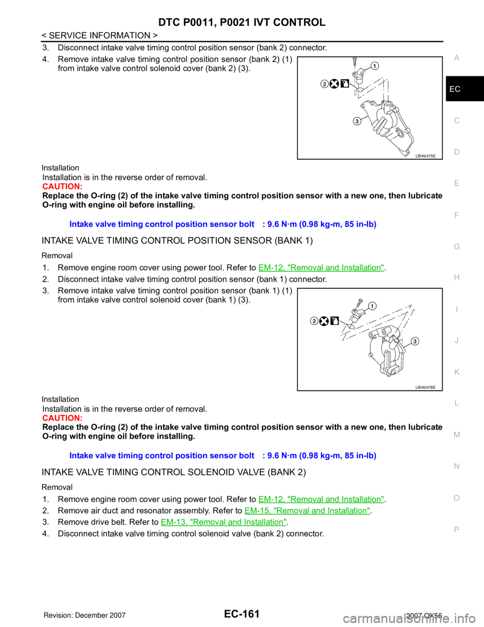
3. Disconnect intake valve timing control position sensor (bank 2) connector.
4. Remove intake valve timing control position sensor (bank 2) (1)
from intake valve control solenoid cover (bank 2) (3).
Installation
Installation is in the reverse order of removal.
CAUTION:
Replace the O-ring (2) of the intake valve timing control position sensor with a new one, then lubricate
O-ring with engine oil before installing.
INTAKE VALVE TIMING CONTROL POSITION SENSOR (BANK 1)
Removal
1. Remove engine room cover using power tool. Refer to EM-12, "Removal and Installation".
2. Disconnect intake valve timing control position sensor (bank 1) connector.
3. Remove intake valve timing control position sensor (bank 1) (1)
from intake valve control solenoid cover (bank 1) (3).
Installation
Installation is in the reverse order of removal.
CAUTION:
Replace the O-ring (2) of the intake valve timing control position sensor with a new one, then lubricate
O-ring with engine oil before installing.
INTAKE VALVE TIMING CONTROL SOLENOID VALVE (BANK 2)
Removal
1. Remove engine room cover using power tool. Refer to EM-12, "Removal and Installation".
2. Remove air duct and resonator assembly. Refer to EM-15, "
Removal and Installation".
3. Remove drive belt. Refer to EM-13, "
Removal and Installation".
4. Disconnect intake valve timing control solenoid valve (bank 2) connector.
LBIA0475E
Intake valve timing control position sensor bolt : 9.6 N·m (0.98 kg-m, 85 in-lb)
LBIA0476E
Intake valve timing control position sensor bolt : 9.6 N·m (0.98 kg-m, 85 in-lb)
Page 1245 of 3061

EC-162
< SERVICE INFORMATION >
DTC P0011, P0021 IVT CONTROL
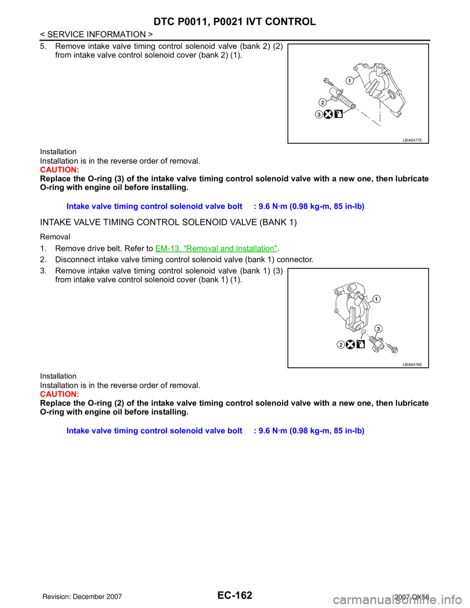
5. Remove intake valve timing control solenoid valve (bank 2) (2)
from intake valve control solenoid cover (bank 2) (1).
Installation
Installation is in the reverse order of removal.
CAUTION:
Replace the O-ring (3) of the intake valve timing control solenoid valve with a new one, then lubricate
O-ring with engine oil before installing.
INTAKE VALVE TIMING CONTROL SOLENOID VALVE (BANK 1)
Removal
1. Remove drive belt. Refer to EM-13, "Removal and Installation".
2. Disconnect intake valve timing control solenoid valve (bank 1) connector.
3. Remove intake valve timing control solenoid valve (bank 1) (3)
from intake valve control solenoid cover (bank 1) (1).
Installation
Installation is in the reverse order of removal.
CAUTION:
Replace the O-ring (2) of the intake valve timing control solenoid valve with a new one, then lubricate
O-ring with engine oil before installing.
LBIA0477E
Intake valve timing control solenoid valve bolt : 9.6 N·m (0.98 kg-m, 85 in-lb)
LBIA0478E
Intake valve timing control solenoid valve bolt : 9.6 N·m (0.98 kg-m, 85 in-lb)