Page 1826 of 3061

EM-56
< SERVICE INFORMATION >
CAMSHAFT
2. Perform the following procedure so as to prevent the engine from being unintentionally started while
checking.
a. Release fuel pressure. Refer to EC-80, "
Fuel Pressure Check".
b. Disconnect ignition coil and injector harness connectors if practical.
3. Remove IVT control solenoid valve.
4. Crank engine, and then make sure that engine oil comes out from IVT control cover oil hole. End cranking
after checking.
WARNING:
Be careful not to touch rotating parts (drive be lts, idler pulley, and crankshaft pulley, etc.).
CAUTION:
• Engine oil may squirt from IVT control soleno id valve installation hole during cranking. Use a
shop cloth to prevent engine oil from splashin g on worker, engine components and vehicle.
• Do not allow engine oil to get on rubber compon ents such as drive belts or engine mount insula-
tors. Immediately wipe off any splashed engine oil.
5. Clean oil groove between oil strainer and IVT control solenoid valve if engine oil does not come out from IVT control valve cover oil hole. Refer to LU-7, "
Schematic".
6. Remove components between IVT control solenoid va lve and camshaft sprocket (INT), and then check
each oil groove for clogging.
• Clean oil groove if necessary.
7. After inspection, installation of the remaining components is in the reverse order of removal.
Valve ClearanceINFOID:0000000003531536
INSPECTION
NOTE:
Perform the following inspection after removal, installation or replacement of camshaft or valve-related parts,
or if there are unusual engine conditions due to changes in valve clearance over time (starting, idling, and/or
noise).
1. Warm up the engine. Then stop the engine.
2. Remove the engine cover and. Refer to EM-12, "
Removal and Installation".
3. Remove the battery cover. Refer to SC-8, "
Removal and Installation".
4. Remove the air cleaner and air duct assembly EM-15, "
Removal and Installation".
5. Remove the RH bank and LH bank rocker covers using power tool. Refer to EM-35, "
Removal and Instal-
lation".
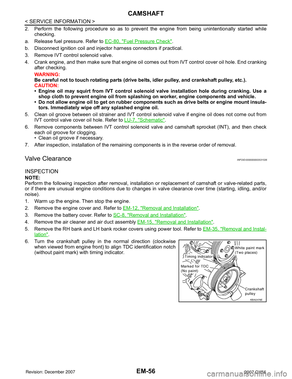
6. Turn the crankshaft pulley in the normal direction (clockwise when viewed from engine front) to align TDC identification notch
(without paint mark) with timing indicator.
KBIA2476E
Page 1835 of 3061

CYLINDER HEADEM-65
< SERVICE INFORMATION >
C
DE
F
G H
I
J
K L
M A
EM
NP
O
Removal and InstallationINFOID:0000000003531541
REMOVAL
1. Remove the engine assembly from the vehicle. Refer to
EM-74, "Removal and Installation".
2. Remove the following components and related parts: • Drive belt auto tensioner drive belts and idler pulley. Refer to EM-13, "
Removal and Installation".
• Thermostat housing and hose. Refer to CO-20, "
Removal and Installation".
• Oil pan and oil strainer. Refer to EM-24, "
Removal and Installation".
• Fuel tube and fuel injector assembly. Refer to EM-31, "
Removal and Installation".
• Intake manifold. Refer to EM-17, "
Removal and Installation".
• Ignition coil. Refer to EM-28, "
Removal and Installation".
• Rocker cover. Refer to EM-35, "
Removal and Installation".
3. Remove the crankshaft pulley, front cover, oil pump, and timing chain. Refer to EM-38, "
Removal and
Installation".
4. Remove the camshaft sprockets and camshafts. Refer to EM-46, "
Removal and Installation".
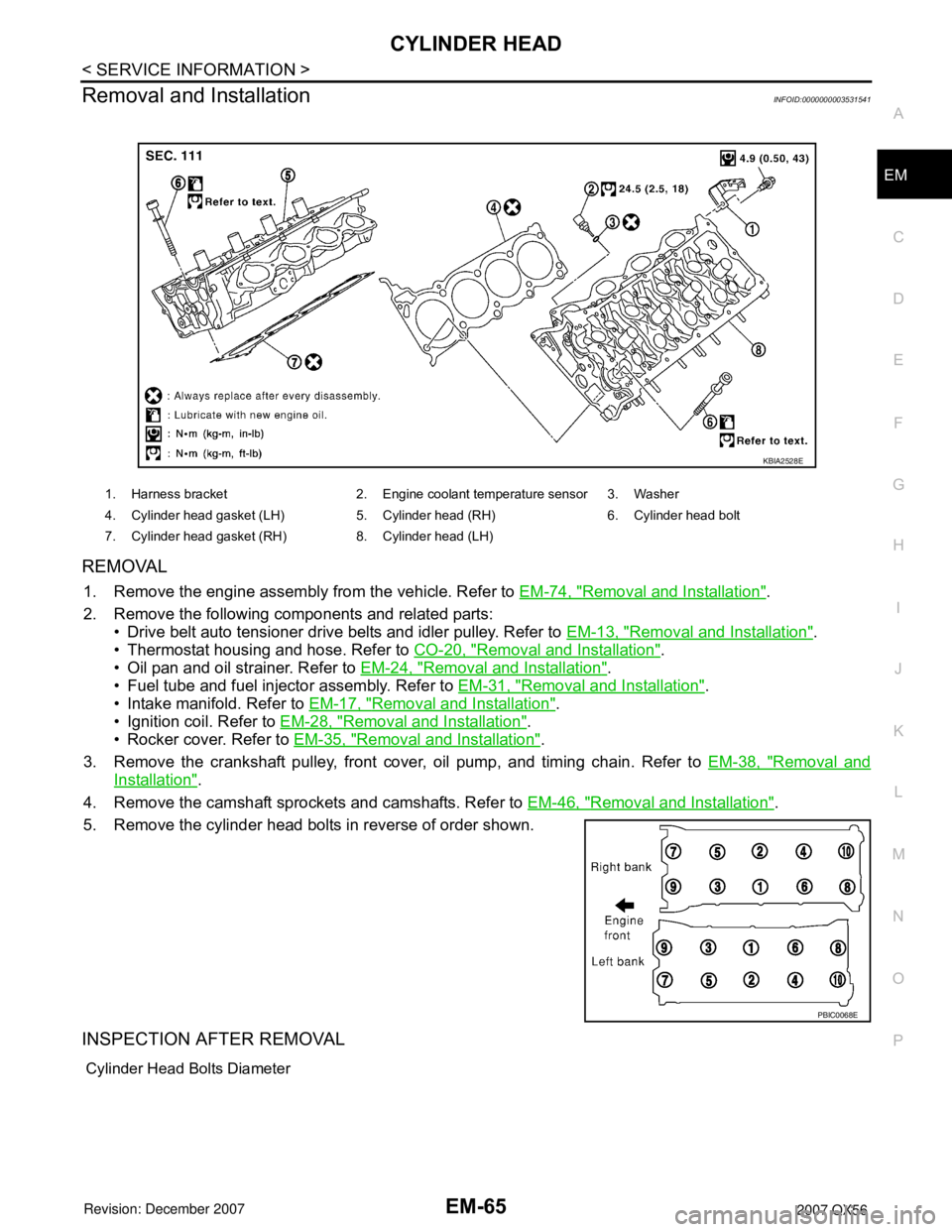
5. Remove the cylinder head bolts in reverse of order shown.
INSPECTION AFTER REMOVAL
Cylinder Head Bolts Diameter
1. Harness bracket 2. Engine coolant temperature sensor 3. Washer
4. Cylinder head gasket (LH) 5. Cylinder head (RH) 6. Cylinder head bolt
7. Cylinder head gasket (RH) 8. Cylinder head (LH)
KBIA2528E
PBIC0068E
Page 2591 of 3061

RSU-1
SUSPENSION
C
D
F
G
H
I
J
K
L
M
SECTION RSU
A
B
RSU
N
O
PCONTENTS
REAR SUSPENSION
SERVICE INFORMATION ............................2
PRECAUTIONS ...................................................2
Precaution for Supplemental Restraint System
(SRS) "AIR BAG" and "SEAT BELT PRE-TEN-
SIONER" ...................................................................
2
Precaution for Rear Suspension ...............................2
PREPARATION ...................................................3
Commercial Service Tool ..........................................3
NOISE, VIBRATION AND HARSHNESS
(NVH) TROUBLESHOOTING .............................
4
NVH Troubleshooting Chart ......................................4
CAN COMMUNICATION .....................................5
System Description ...................................................5
TROUBLE DIAGNOSIS ......................................6
How to Perform Trouble Diagnosis for Quick and
Accurate Repair ........................................................
6
Component Parts and Harness Connector Loca-
tion ............................................................................
8
Wiring Diagram - A/SUSP - .......................................9
Basic Inspection ......................................................10
Chek Suspension Indicator Lamp Timing ...............11
Control Unit Input/Output Signal Standard ..............11
CONSULT-II Function (AIR LEVELIZER) ...............11
TROUBLE DIAGNOSIS FOR SELF-DIAG-
NOSTIC ITEMS ..................................................
14
Height Sensor System Inspection ...........................14
Exhaust Valve Solenoid System Inspection ............15
Compressor Motor, Compressor Motor Relay and
Circuit Inspection .....................................................
17
TROUBLE DIAGNOSES FOR SYMPTOMS ......19
Load Leveling Rear Air Suspension System Does
Not Operate .............................................................
19
Chek Suspension Indicator Lamp Stays On When
Ignition Switch Is Turned On ...................................
20
REAR SUSPENSION ASSEMBLY ...................21
Component ..............................................................21
On-Vehicle Inspection and Service .........................22
Wheel AlignmentInspection .....................................23
REAR SUSPENSION MEMBER .......................26
Removal and Installation .........................................26
SHOCK ABSORBER ........................................30
Removal and Installation .........................................30
SUSPENSION ARM ..........................................31
Removal and Installation .........................................31
FRONT LOWER LINK .......................................33
Removal and Installation .........................................33
REAR LOWER LINK & COIL SPRING .............35
Removal and Installation .........................................35
STABILIZER BAR .............................................37
Removal and Installation .........................................37
REAR LOAD LEVELING AIR SUSPENSION
COMPRESSOR ASSEMBLY ............................
38
Removal and Installation .........................................38
HEIGHT SENSOR .............................................40
Removal and Installation .........................................40
CONTROL UNIT ................................................42
Removal and Installation .........................................42
Initialization Procedure ............................................42
SERVICE DATA AND SPECIFICATIONS
(SDS) .................................................................
43
Wheel Alignment .....................................................43
Ball Joint ..................................................................43
Wheelarch Height (Unladen*1) ................................44
Page:
< prev 1-8 9-16 17-24