2007 INFINITI QX56 lock
[x] Cancel search: lockPage 1868 of 3061
EM-98
< SERVICE INFORMATION >
CYLINDER BLOCK
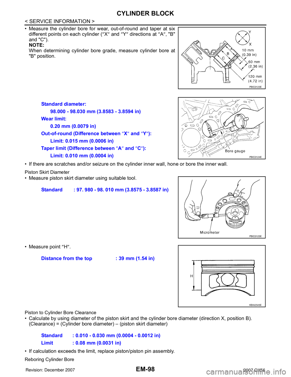
• Measure the cylinder bore for wear, out-of-round and taper at six
different points on each cylinder (″X″ and ″Y″ directions at ″A″, "B"
and "C").
NOTE:
When determining cylinder bore grade, measure cylinder bore at
"B" position.
• If there are scratches and/or seizure on the cylinder inner wall, hone or bore the inner wall.
Piston Skirt Diameter
• Measure piston skirt diameter using suitable tool.
• Measure point ″H″.
Piston to Cylinder Bore Clearance
• Calculate by using diameter of the piston skirt and the cylinder bore diameter (direction X, position B).
(Clearance) = (Cylinder bore diameter) – (piston skirt diameter)
• If calculation exceeds the limit, replace piston/piston pin assembly.
Reboring Cylinder Bore
PBIC0123E
Standard diameter:
98.000 - 98.030 mm (3.8583 - 3.8594 in)
Wear limit:
0.20 mm (0.0079 in)
Out-of-round (Difference between ″X″ and ″Y″):
Limit: 0.015 mm (0.0006 in)
Taper limit (Difference between ″A″ and ″C″):
Limit: 0.010 mm (0.0004 in)
PBIC0124E
Standard : 97. 980 - 98. 010 mm (3.8575 - 3.8587 in)
PBIC0125E
Distance from the top : 39 mm (1.54 in)
KBIA2545E
Standard : 0.010 - 0.030 mm (0.0004 - 0.0012 in)
Limit : 0.08 mm (0.0031 in)
Page 1869 of 3061
CYLINDER BLOCK
EM-99
< SERVICE INFORMATION >
C
D
E
F
G
H
I
J
K
L
MA
EM
N
P O
1. Cylinder bore size is determined by adding piston-to-bore clearance to piston diameter “A”.
2. Install main bearing caps, and tighten them to the specified torque. Otherwise, cylinder bores may be dis-
torted in final assembly.
3. Cut the cylinder bores.
NOTE:
• When any cylinder needs boring, all other cylinders must also be bored.
• Do not cut too much out of cylinder bore at one time. Cut only 0.05 mm (0.0020 in) or so in diameter at a
time.
4. Hone cylinders to obtain the specified piston-to-bore clearance.
5. Measure finished cylinder bore for out-of-round and taper.
NOTE:
Measurement should be done after cylinder bore cools down.
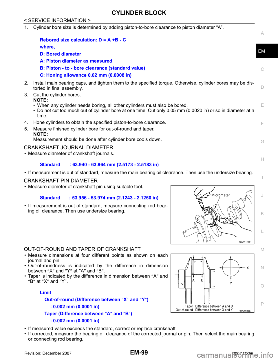
CRANKSHAFT JOURNAL DIAMETER
• Measure diameter of crankshaft journals.
• If measurement is out of standard, measure the main bearing oil clearance. Then use the undersize bearing.
CRANKSHAFT PIN DIAMETER
• Measure diameter of crankshaft pin using suitable tool.
• If measurement is out of standard, measure connecting rod bear-
ing oil clearance. Then use undersize bearing.
OUT-OF-ROUND AND TAPER OF CRANKSHAFT
• Measure dimensions at four different points as shown on each
journal and pin.
• Out-of-roundness is indicated by the difference in dimension
between ″X″ and ″Y″ at ″A″ and ″B″.
• Taper is indicated by the difference in dimension between ″A″ and
″B″ at ″X″ and ″Y″.
• If measured value exceeds the standard, correct or replace crankshaft.
• If corrected, measure the bearing oil clearance of the corrected journal or pin. Then select the main bearing
or connecting rod bearing. Rebored size calculation: D = A +B - C
where,
D: Bored diameter
A: Piston diameter as measured
B: Piston - to - bore clearance (standard value)
C: Honing allowance 0.02 mm (0.0008 in)
Standard : 63.940 - 63.964 mm (2.5173 - 2.5183 in)
Standard : 53.956 - 53.974 mm (2.1243 - 2.1250 in)
PBIC0127E
Limit
Out-of-round (Difference between ″X″ and ″Y″)
: 0.002 mm (0.0001 in)
Taper (Difference between ″A″ and ″B″)
: 0.002 mm (0.0001 in)
PBIC1685E
Page 1870 of 3061
EM-100
< SERVICE INFORMATION >
CYLINDER BLOCK
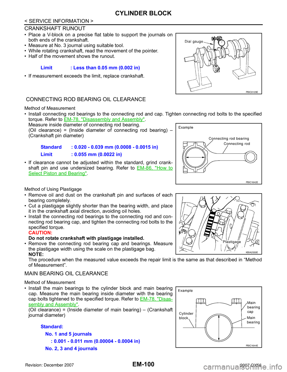
CRANKSHAFT RUNOUT
• Place a V-block on a precise flat table to support the journals on
both ends of the crankshaft.
• Measure at No. 3 journal using suitable tool.
• While rotating crankshaft, read the movement of the pointer.
• Half of the movement shows the runout.
• If measurement exceeds the limit, replace crankshaft.
CONNECTING ROD BEARING OIL CLEARANCE
Method of Measurement
• Install connecting rod bearings to the connecting rod and cap. Tighten connecting rod bolts to the specified
torque. Refer to EM-78, "
Disassembly and Assembly".
Measure inside diameter of connecting rod bearing.
(Oil clearance) = (Inside diameter of connecting rod bearing) –
(Crankshaft pin diameter)
• If clearance cannot be adjusted within the standard, grind crank-
shaft pin and use undersized bearing. Refer to EM-86, "
How to
Select Piston and Bearing".
Method of Using Plastigage
• Remove oil and dust on the crankshaft pin and surfaces of each
bearing completely.
• Cut a plastigage slightly shorter than the bearing width, and place
it in the crankshaft axial direction, avoiding oil holes.
• Install the connecting rod bearings to the connecting rod and con-
necting rod bearing cap, and tighten the connecting rod bolts to the
specified torque.
CAUTION:
Do not rotate crankshaft with plastigage installed.
• Remove the connecting rod bearing cap and bearings. Measure
the plastigage width using the scale on the plastigage bag.
NOTE:
The procedure when the measured value exceeds the repair limit is the same as that described in “Method
of Measurement”.
MAIN BEARING OIL CLEARANCE
Method of Measurement
• Install the main bearings to the cylinder block and main bearing
cap. Measure the main bearing inside diameter with the bearing
cap bolts tightened to the specified torque. Refer to EM-78, "
Disas-
sembly and Assembly".
(Oil clearance) = (Inside diameter of main bearing) – (Crankshaft
journal diameter)Limit : Less than 0.05 mm (0.002 in)
PBIC0129E
Standard : 0.020 - 0.039 mm (0.0008 - 0.0015 in)
Limit : 0.055 mm (0.0022 in)
PBIC1642E
KBIA2550E
Standard:
No. 1 and 5 journals
: 0.001 - 0.011 mm (0.00004 - 0.0004 in)
No. 2, 3 and 4 journals
PBIC1644E
Page 1871 of 3061
CYLINDER BLOCK
EM-101
< SERVICE INFORMATION >
C
D
E
F
G
H
I
J
K
L
MA
EM
N
P O
• If measured value exceeds the repair limit, select main bearings referring to the main bearing inside diame-
ter and crankshaft journal diameter, so that the oil clearance satisfies the standard. Refer to EM-86, "
How to
Select Piston and Bearing".
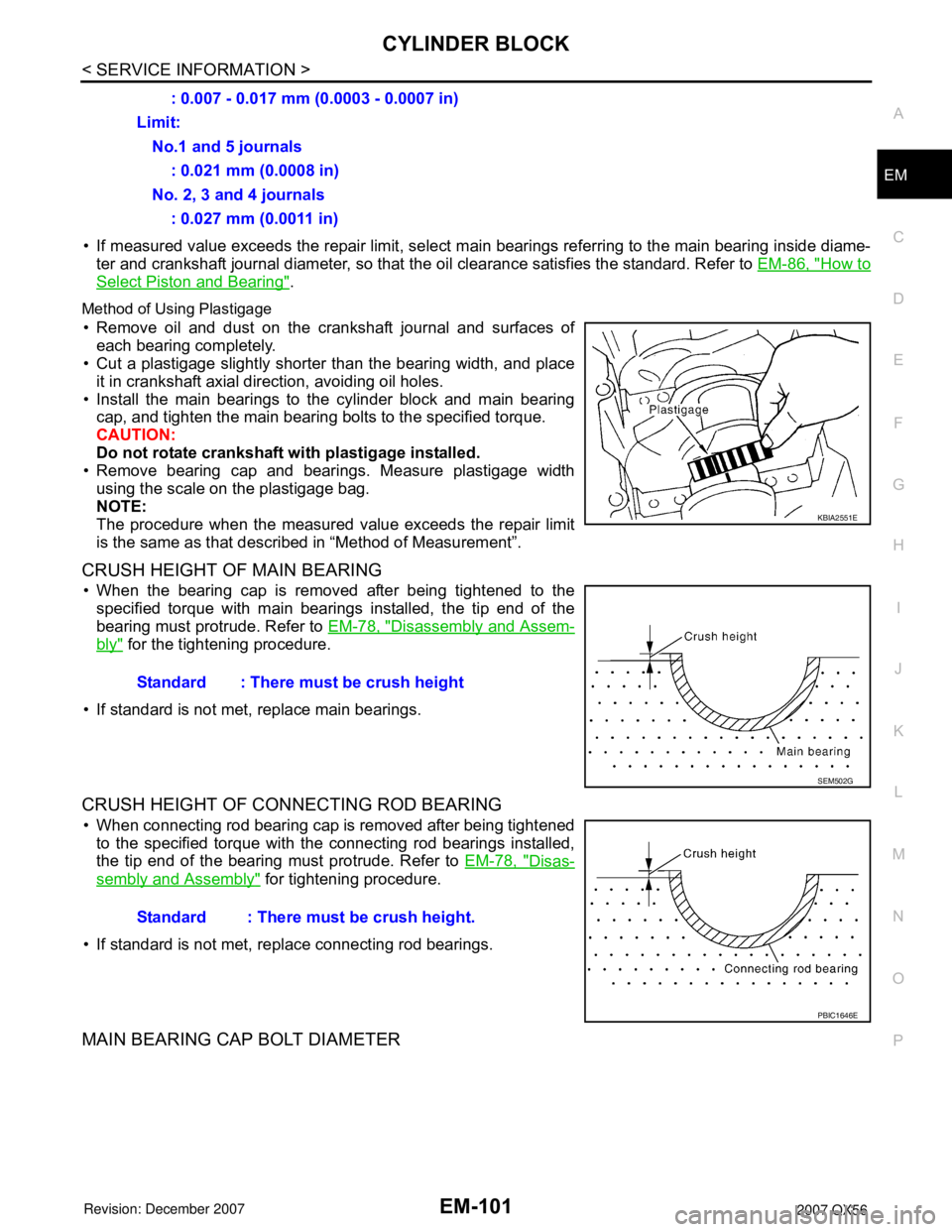
Method of Using Plastigage
• Remove oil and dust on the crankshaft journal and surfaces of
each bearing completely.
• Cut a plastigage slightly shorter than the bearing width, and place
it in crankshaft axial direction, avoiding oil holes.
• Install the main bearings to the cylinder block and main bearing
cap, and tighten the main bearing bolts to the specified torque.
CAUTION:
Do not rotate crankshaft with plastigage installed.
• Remove bearing cap and bearings. Measure plastigage width
using the scale on the plastigage bag.
NOTE:
The procedure when the measured value exceeds the repair limit
is the same as that described in “Method of Measurement”.
CRUSH HEIGHT OF MAIN BEARING
• When the bearing cap is removed after being tightened to the
specified torque with main bearings installed, the tip end of the
bearing must protrude. Refer to EM-78, "
Disassembly and Assem-
bly" for the tightening procedure.
• If standard is not met, replace main bearings.
CRUSH HEIGHT OF CONNECTING ROD BEARING
• When connecting rod bearing cap is removed after being tightened
to the specified torque with the connecting rod bearings installed,
the tip end of the bearing must protrude. Refer to EM-78, "
Disas-
sembly and Assembly" for tightening procedure.
• If standard is not met, replace connecting rod bearings.
MAIN BEARING CAP BOLT DIAMETER
: 0.007 - 0.017 mm (0.0003 - 0.0007 in)
Limit:
No.1 and 5 journals
: 0.021 mm (0.0008 in)
No. 2, 3 and 4 journals
: 0.027 mm (0.0011 in)
KBIA2551E
Standard : There must be crush height
SEM502G
Standard : There must be crush height.
PBIC1646E
Page 1872 of 3061
EM-102
< SERVICE INFORMATION >
CYLINDER BLOCK
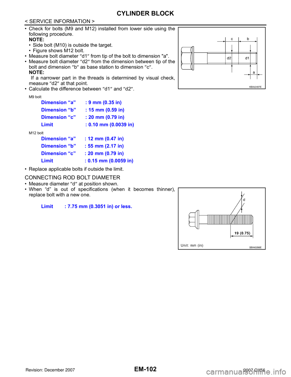
• Check for bolts (M9 and M12) installed from lower side using the
following procedure.
NOTE:
• Side bolt (M10) is outside the target.
• Figure shows M12 bolt.
• Measure bolt diameter ″d1″ from tip of the bolt to dimension "a".
• Measure bolt diameter ″d2″ from the dimension between tip of the
bolt and dimension ″b″ as base station to dimension ″c″.
NOTE:
If a narrower part in the threads is determined by visual check,
measure ″d2″ at that point.
• Calculate the difference between ″d1″ and ″d2″.
M9 bolt
M12 bolt
• Replace applicable bolts if outside the limit.
CONNECTING ROD BOLT DIAMETER
• Measure diameter ″d″ at position shown.
• When “d” is out of specifications (when it becomes thinner),
replace bolt with a new one.
KBIA2497E
Dimension “a” : 9 mm (0.35 in)
Dimension “b” : 15 mm (0.59 in)
Dimension “c” : 20 mm (0.79 in)
Limit : 0.10 mm (0.0039 in)
Dimension “a” : 12 mm (0.47 in)
Dimension “b” : 55 mm (2.17 in)
Dimension “c” : 20 mm (0.79 in)
Limit : 0.15 mm (0.0059 in)
Limit : 7.75 mm (0.3051 in) or less.
SBIA0286E
Page 1877 of 3061
SERVICE DATA AND SPECIFICATIONS (SDS)
EM-107
< SERVICE INFORMATION >
C
D
E
F
G
H
I
J
K
L
MA
EM
N
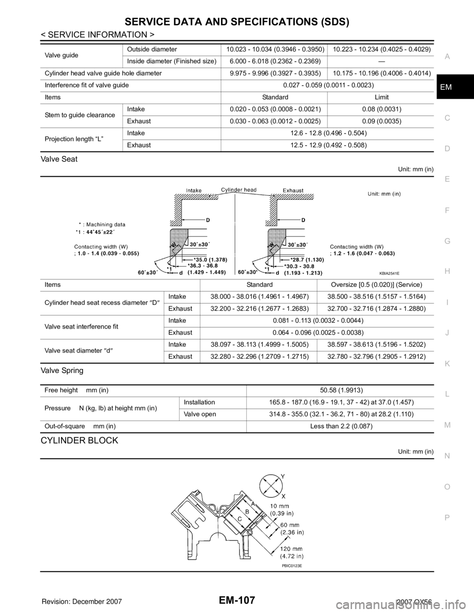
P O Valve Seat
Unit: mm (in)
Va l v e Sp r i n g
CYLINDER BLOCK
Unit: mm (in)
Valve guideOutside diameter 10.023 - 10.034 (0.3946 - 0.3950) 10.223 - 10.234 (0.4025 - 0.4029)
Inside diameter (Finished size) 6.000 - 6.018 (0.2362 - 0.2369) —
Cylinder head valve guide hole diameter 9.975 - 9.996 (0.3927 - 0.3935) 10.175 - 10.196 (0.4006 - 0.4014)
Interference fit of valve guide 0.027 - 0.059 (0.0011 - 0.0023)
Items Standard Limit
Stem to guide clearanceIntake 0.020 - 0.053 (0.0008 - 0.0021) 0.08 (0.0031)
Exhaust 0.030 - 0.063 (0.0012 - 0.0025) 0.09 (0.0035)
Projection length “L”Intake 12.6 - 12.8 (0.496 - 0.504)
Exhaust 12.5 - 12.9 (0.492 - 0.508)
Items Standard Oversize [0.5 (0.020)] (Service)
Cylinder head seat recess diameter ″D″Intake 38.000 - 38.016 (1.4961 - 1.4967) 38.500 - 38.516 (1.5157 - 1.5164)
Exhaust 32.200 - 32.216 (1.2677 - 1.2683) 32.700 - 32.716 (1.2874 - 1.2880)
Valve seat interference fitIntake 0.081 - 0.113 (0.0032 - 0.0044)
Exhaust 0.064 - 0.096 (0.0025 - 0.0038)
Valve seat diameter ″d″Intake 38.097 - 38.113 (1.4999 - 1.5005) 38.597 - 38.613 (1.5196 - 1.5202)
Exhaust 32.280 - 32.296 (1.2709 - 1.2715) 32.780 - 32.796 (1.2905 - 1.2912)
KBIA2541E
Free height mm (in)50.58 (1.9913)
Pressure N (kg, lb) at height mm (in)Installation 165.8 - 187.0 (16.9 - 19.1, 37 - 42) at 37.0 (1.457)
Valve open 314.8 - 355.0 (32.1 - 36.2, 71 - 80) at 28.2 (1.110)
Out-of-square mm (in) Less than 2.2 (0.087)
PBIC0123E
Page 1892 of 3061
FAX-6
< SERVICE INFORMATION >
WHEEL HUB
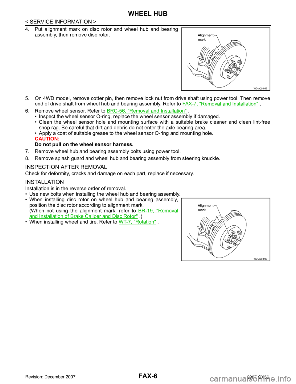
4. Put alignment mark on disc rotor and wheel hub and bearing
assembly, then remove disc rotor.
5. On 4WD model, remove cotter pin, then remove lock nut from drive shaft using power tool. Then remove
end of drive shaft from wheel hub and bearing assembly. Refer to FA X - 7 , "
Removal and Installation" .
6. Remove wheel sensor. Refer to BRC-56, "
Removal and Installation" .
• Inspect the wheel sensor O-ring, replace the wheel sensor assembly if damaged.
• Clean the wheel sensor hole and mounting surface with a suitable brake cleaner and clean lint-free
shop rag. Be careful that dirt and debris do not enter the axle bearing area.
• Apply a coat of suitable grease to the wheel sensor O-ring and mounting hole.
CAUTION:
Do not pull on the wheel sensor harness.
7. Remove wheel hub and bearing assembly bolts using power tool.
8. Remove splash guard and wheel hub and bearing assembly from steering knuckle.
INSPECTION AFTER REMOVAL
Check for deformity, cracks and damage on each part, replace if necessary.
INSTALLATION
Installation is in the reverse order of removal.
• Use new bolts when installing the wheel hub and bearing assembly.
• When installing disc rotor on wheel hub and bearing assembly,
position the disc rotor according to alignment mark.
(When not using the alignment mark, refer to BR-19, "
Removal
and Installation of Brake Caliper and Disc Rotor" .)
• When installing wheel and tire. Refer to WT-7, "
Rotation" .
WDIA0044E
WDIA0044E
Page 1907 of 3061
FFD-8
< SERVICE INFORMATION >
FRONT OIL SEAL
FRONT OIL SEAL
Removal and InstallationINFOID:0000000003532590
REMOVAL
1. Remove the drive shafts from the front final drive assembly. Refer to FAX-7, "Removal and Installation".
2. Remove the front propeller shaft from the front final drive assembly. Refer to PR-4, "
Removal and Installa-
tion".
3. Measure the total preload torque. Refer to FFD-13, "
Disassembly and Assembly".
NOTE:
Record the total preload torque measurement.
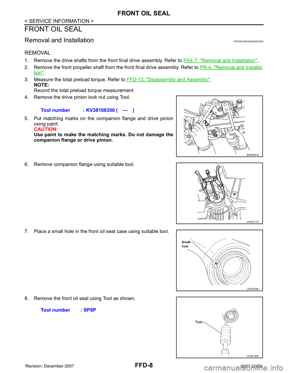
4. Remove the drive pinion lock nut using Tool.
5. Put matching marks on the companion flange and drive pinion
using paint.
CAUTION:
Use paint to make the matching marks. Do not damage the
companion flange or drive pinion.
6. Remove companion flange using suitable tool.
7. Place a small hole in the front oil seal case using suitable tool.
8. Remove the front oil seal using Tool as shown.Tool number : KV38108300 ( — )
BDIA0001E
LDIA0171E
LDIA0129E
Tool number : SP8P
LDIA0130E