Page 1908 of 3061
FRONT OIL SEAL
FFD-9
< SERVICE INFORMATION >
C
E
F
G
H
I
J
K
L
MA
B
FFD
N
O
P
INSTALLATION
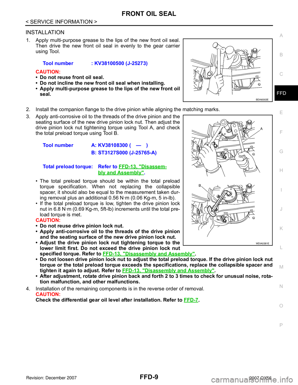
1. Apply multi-purpose grease to the lips of the new front oil seal.
Then drive the new front oil seal in evenly to the gear carrier
using Tool.
CAUTION:
• Do not reuse front oil seal.
• Do not incline the new front oil seal when installing.
• Apply multi-purpose grease to the lips of the new front oil
seal.
2. Install the companion flange to the drive pinion while aligning the matching marks.
3. Apply anti-corrosive oil to the threads of the drive pinion and the
seating surface of the new drive pinion lock nut. Then adjust the
drive pinion lock nut tightening torque using Tool A, and check
the total preload torque using Tool B.
• The total preload torque should be within the total preload
torque specification. When not replacing the collapsible
spacer, it should also be equal to the measurement taken dur-
ing removal plus an additional 0.56 N·m (0.06 Kg-m, 5 in-lb).
• If the total preload torque is low, tighten the drive pinion lock
nut in 6.8 N·m (0.69 Kg-m, 5ft-lb) increments until the total pre-
load torque is met.
CAUTION:
• Do not reuse drive pinion lock nut.
• Apply anti-corrosive oil to the threads of the drive pinion
and the seating surface of the new drive pinion lock nut.
• Adjust the drive pinion lock nut tightening torque to the
lower limit first. Do not exceed the drive pinion lock nut
specified torque. Refer to FFD-13, "
Disassembly and Assembly".
• Do not loosen drive pinion lock nut to adjust the total preload torque. If the drive pinion lock nut
torque or the total preload torque exceeds the specifications, replace the collapsible spacer and
tighten it again to adjust. Refer to FFD-13, "
Disassembly and Assembly".
• After adjustment, rotate drive pinion back and forth 2 to 3 times to check for unusual noise, rota-
tion malfunction, and other malfunctions.
4. Installation of the remaining components is in the reverse order of removal.
CAUTION:
Check the differential gear oil level after installation. Refer to FFD-7
. Tool number : KV38100500 (J-25273)
BDIA0003E
Tool number A: KV38108300 ( — )
B: ST3127S000 (J-25765-A)
Total preload torque: Refer to FFD-13, "
Disassem-
bly and Assembly".
WDIA0381E
Page 1913 of 3061
FFD-14
< SERVICE INFORMATION >
FRONT FINAL DRIVE ASSEMBLY
ASSEMBLY INSPECTION AND ADJUSTMENT
• Drain the differential gear oil before inspection and adjustment. Refer to FFD-7.
• Remove and install the carrier cover as necessary for inspection and adjustment. Refer to FFD-11
.
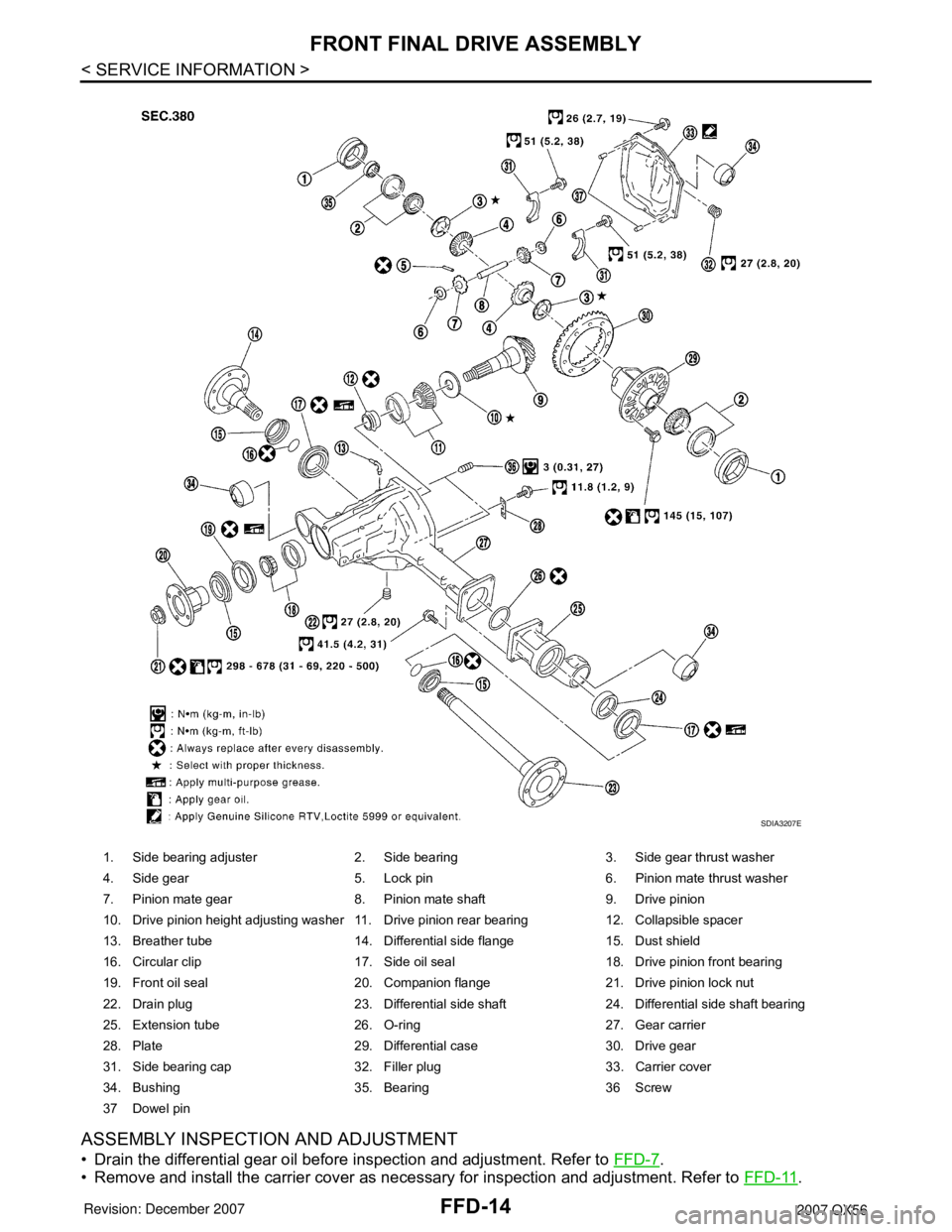
1. Side bearing adjuster 2. Side bearing 3. Side gear thrust washer
4. Side gear 5. Lock pin 6. Pinion mate thrust washer
7. Pinion mate gear 8. Pinion mate shaft 9. Drive pinion
10. Drive pinion height adjusting washer 11. Drive pinion rear bearing 12. Collapsible spacer
13. Breather tube 14. Differential side flange 15. Dust shield
16. Circular clip 17. Side oil seal 18. Drive pinion front bearing
19. Front oil seal 20. Companion flange 21. Drive pinion lock nut
22. Drain plug 23. Differential side shaft 24. Differential side shaft bearing
25. Extension tube 26. O-ring 27. Gear carrier
28. Plate 29. Differential case 30. Drive gear
31. Side bearing cap 32. Filler plug 33. Carrier cover
34. Bushing 35. Bearing 36 Screw
37 Dowel pin
SDIA3207E
Page 1914 of 3061
FRONT FINAL DRIVE ASSEMBLY
FFD-15
< SERVICE INFORMATION >
C
E
F
G
H
I
J
K
L
MA
B
FFD
N
O
P Total Preload Torque
1. Install the differential side shaft and differential side flange if necessary.
CAUTION:
The differential side shaft and differential side flange must be installed in order to measure total
preload torque.
2. Rotate the drive pinion back and forth 2 to 3 times to check for unusual noise and rotation malfunction.
3. Rotate the drive pinion at least 20 times to check for smooth operation of the bearings.
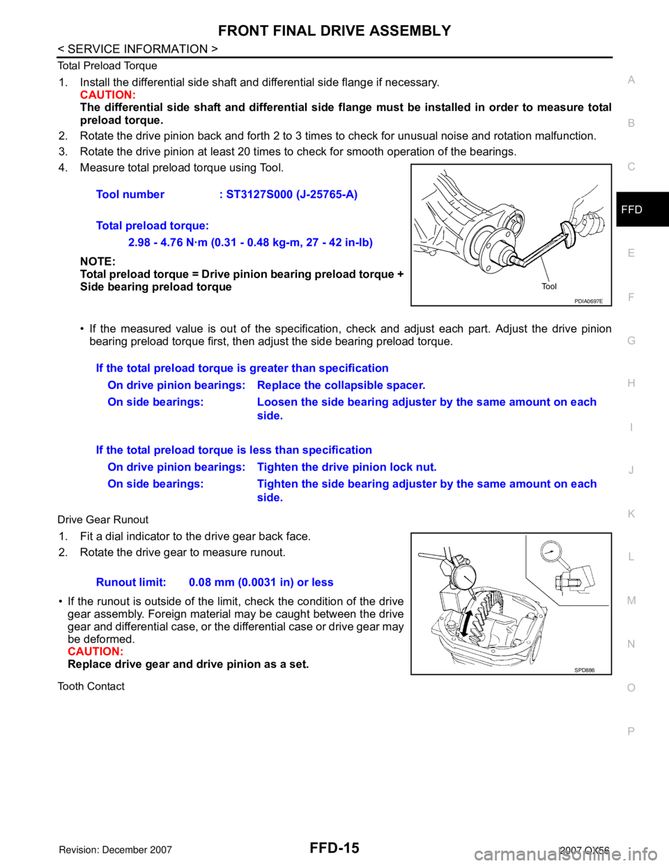
4. Measure total preload torque using Tool.
NOTE:
Total preload torque = Drive pinion bearing preload torque +
Side bearing preload torque
• If the measured value is out of the specification, check and adjust each part. Adjust the drive pinion
bearing preload torque first, then adjust the side bearing preload torque.
Drive Gear Runout
1. Fit a dial indicator to the drive gear back face.
2. Rotate the drive gear to measure runout.
• If the runout is outside of the limit, check the condition of the drive
gear assembly. Foreign material may be caught between the drive
gear and differential case, or the differential case or drive gear may
be deformed.
CAUTION:
Replace drive gear and drive pinion as a set.
Tooth Contact
Tool number : ST3127S000 (J-25765-A)
Total preload torque:
2.98 - 4.76 N·m (0.31 - 0.48 kg-m, 27 - 42 in-lb)
PDIA0697E
If the total preload torque is greater than specification
On drive pinion bearings: Replace the collapsible spacer.
On side bearings: Loosen the side bearing adjuster by the same amount on each
side.
If the total preload torque is less than specification
On drive pinion bearings: Tighten the drive pinion lock nut.
On side bearings: Tighten the side bearing adjuster by the same amount on each
side.
Runout limit: 0.08 mm (0.0031 in) or less
SPD886
Page 1919 of 3061
FFD-20
< SERVICE INFORMATION >
FRONT FINAL DRIVE ASSEMBLY
• Keep side bearing outer races together with side bearing
inner races. Do not mix them up.
12. For proper reinstallation, paint matching marks on the differential
case and drive gear.
CAUTION:
Use paint for matching marks. Do not damage differential
case or drive gear.
13. Remove the drive gear bolts.
14. Tap the drive gear off the differential case using suitable tool.
CAUTION:
Tap evenly all around to keep drive gear from bending.
15. Remove the lock pin of the pinion mate shaft from the drive gear
side using suitable tool.
16. Remove the pinion mate shaft.
17. Turn the pinion mate gear, then remove the pinion mate gear,
pinion mate thrust washer, side gear and side gear thrust
washer from the differential case.
SPD022
PDIA0496E
SPD025
SDIA0031J
SDIA0032J
Page 1920 of 3061
FRONT FINAL DRIVE ASSEMBLY
FFD-21
< SERVICE INFORMATION >
C
E
F
G
H
I
J
K
L
MA
B
FFD
N
O
P Drive Pinion Assembly
1. Remove the differential assembly.
2. Remove the drive pinion lock nut using Tool.
3. Put matching marks on the companion flange and drive pinion
using paint.
CAUTION:
Use paint to make the matching marks. Do not damage the
companion flange or drive pinion.
4. Remove the companion flange using suitable tool.
5. Press the drive pinion assembly (with rear inner bearing race
and collapsible spacer) out of the gear carrier.
CAUTION:
Do not drop drive pinion assembly.
6. Remove the drive pinion rear bearing inner race and drive pinion
height adjusting washer using Tool.Tool number : KV38108300 (J-44195)
PDIA0702E
PDIA0703E
SDIA2234E
Tool number : ST30021000 ( — )
S-PD179
Page 1926 of 3061
FRONT FINAL DRIVE ASSEMBLY
FFD-27
< SERVICE INFORMATION >
C
E
F
G
H
I
J
K
L
MA
B
FFD
N
O
P
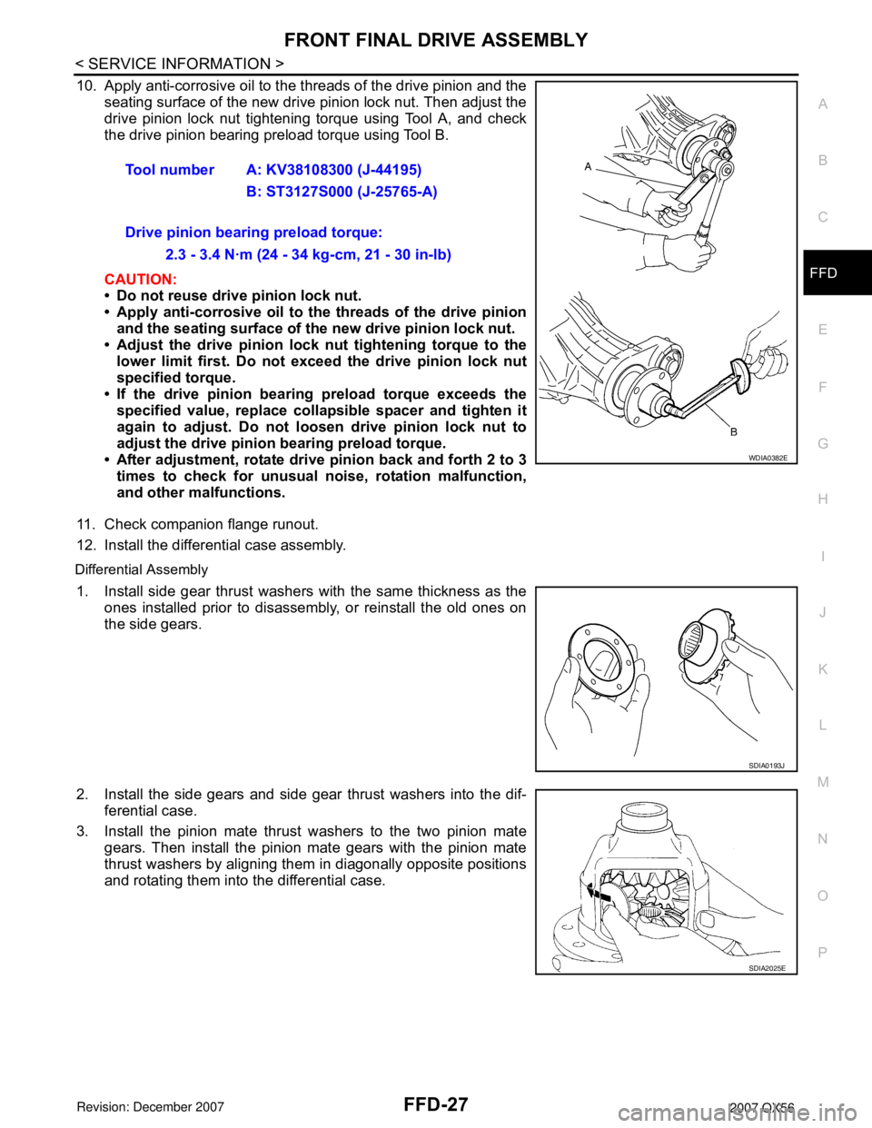
10. Apply anti-corrosive oil to the threads of the drive pinion and the
seating surface of the new drive pinion lock nut. Then adjust the
drive pinion lock nut tightening torque using Tool A, and check
the drive pinion bearing preload torque using Tool B.
CAUTION:
• Do not reuse drive pinion lock nut.
• Apply anti-corrosive oil to the threads of the drive pinion
and the seating surface of the new drive pinion lock nut.
• Adjust the drive pinion lock nut tightening torque to the
lower limit first. Do not exceed the drive pinion lock nut
specified torque.
• If the drive pinion bearing preload torque exceeds the
specified value, replace collapsible spacer and tighten it
again to adjust. Do not loosen drive pinion lock nut to
adjust the drive pinion bearing preload torque.
• After adjustment, rotate drive pinion back and forth 2 to 3
times to check for unusual noise, rotation malfunction,
and other malfunctions.
11. Check companion flange runout.
12. Install the differential case assembly.
Differential Assembly
1. Install side gear thrust washers with the same thickness as the
ones installed prior to disassembly, or reinstall the old ones on
the side gears.
2. Install the side gears and side gear thrust washers into the dif-
ferential case.
3. Install the pinion mate thrust washers to the two pinion mate
gears. Then install the pinion mate gears with the pinion mate
thrust washers by aligning them in diagonally opposite positions
and rotating them into the differential case.Tool number A: KV38108300 (J-44195)
B: ST3127S000 (J-25765-A)
Drive pinion bearing preload torque:
2.3 - 3.4 N·m (24 - 34 kg-cm, 21 - 30 in-lb)
WDIA0382E
SDIA0193J
SDIA2025E
Page 1927 of 3061
FFD-28
< SERVICE INFORMATION >
FRONT FINAL DRIVE ASSEMBLY
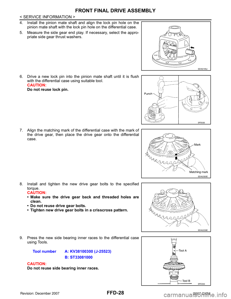
4. Install the pinion mate shaft and align the lock pin hole on the
pinion mate shaft with the lock pin hole on the differential case.
5. Measure the side gear end play. If necessary, select the appro-
priate side gear thrust washers.
6. Drive a new lock pin into the pinion mate shaft until it is flush
with the differential case using suitable tool.
CAUTION:
Do not reuse lock pin.
7. Align the matching mark of the differential case with the mark of
the drive gear, then place the drive gear onto the differential
case.
8. Install and tighten the new drive gear bolts to the specified
torque.
CAUTION:
• Make sure the drive gear back and threaded holes are
clean.
• Do not reuse drive gear bolts.
• Tighten new drive gear bolts in a crisscross pattern.
9. Press the new side bearing inner races to the differential case
using Tools.
CAUTION:
Do not reuse side bearing inner races.
SDIA0195J
SPD030
SDIA2593E
SDIA2239E
Tool number A: KV38100300 (J-25523)
B: ST33081000
SPD353
Page 1934 of 3061
PREPARATION
FL-3
< SERVICE INFORMATION >
C
D
E
F
G
H
I
J
K
L
MA
FL
N
P O
PREPARATION
Special Service ToolINFOID:0000000003532201
The actual shapes of the Kent-Moore tools may differ from those of the special tools illustrated here.
Commercial Service ToolINFOID:0000000003532202
Tool number
(Kent-Moore No.)
Tool nameDescription
—
(J-46536)
Fuel tank lock ring toolRemoving and installing fuel tank lock ring
LBIA0398E
Tool nameDescription
Power toolLoosening bolts and nuts
PBIC0190E