2007 INFINITI QX56 lock
[x] Cancel search: lockPage 1956 of 3061
FSU-10
< SERVICE INFORMATION >
COIL SPRING AND SHOCK ABSORBER
COIL SPRING AND SHOCK ABSORBER
Removal and InstallationINFOID:0000000003532638
REMOVAL
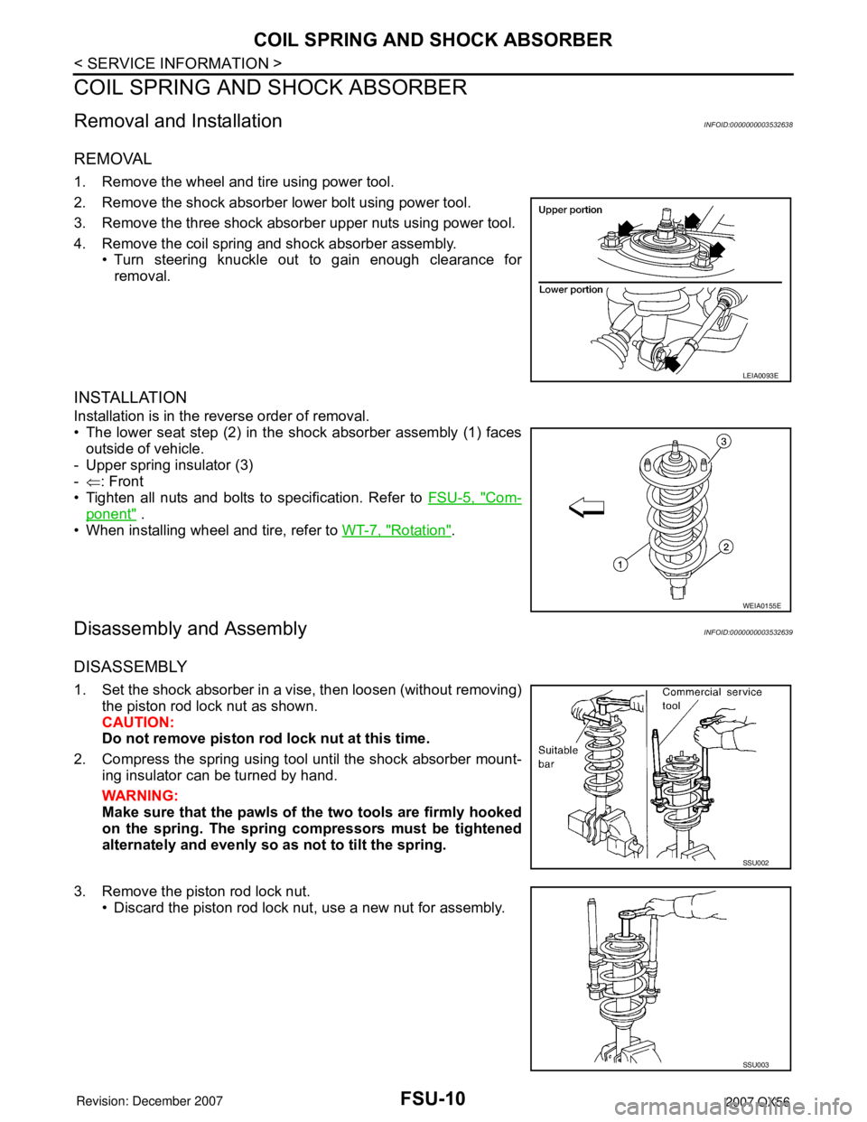
1. Remove the wheel and tire using power tool.
2. Remove the shock absorber lower bolt using power tool.
3. Remove the three shock absorber upper nuts using power tool.
4. Remove the coil spring and shock absorber assembly.
• Turn steering knuckle out to gain enough clearance for
removal.
INSTALLATION
Installation is in the reverse order of removal.
• The lower seat step (2) in the shock absorber assembly (1) faces
outside of vehicle.
- Upper spring insulator (3)
-⇐: Front
• Tighten all nuts and bolts to specification. Refer to FSU-5, "
Com-
ponent" .
• When installing wheel and tire, refer to WT-7, "
Rotation".
Disassembly and AssemblyINFOID:0000000003532639
DISASSEMBLY
1. Set the shock absorber in a vise, then loosen (without removing)
the piston rod lock nut as shown.
CAUTION:
Do not remove piston rod lock nut at this time.
2. Compress the spring using tool until the shock absorber mount-
ing insulator can be turned by hand.
WARNING:
Make sure that the pawls of the two tools are firmly hooked
on the spring. The spring compressors must be tightened
alternately and evenly so as not to tilt the spring.
3. Remove the piston rod lock nut.
• Discard the piston rod lock nut, use a new nut for assembly.
LEIA0093E
WEIA0155E
SSU002
SSU003
Page 1957 of 3061
COIL SPRING AND SHOCK ABSORBER
FSU-11
< SERVICE INFORMATION >
C
D
F
G
H
I
J
K
L
MA
B
FSU
N
O
P
INSPECTION AFTER DISASSEMBLY
Shock Absorber Assembly
• Check for smooth operation through a full stroke, both compression and extension.
• Check for oil leakage on welded or gland packing portions.
• Check piston rod for cracks, deformation or other damage and replace if necessary.
Mounting Insulator and Rubber Parts
Check cemented rubber-to-metal portion for separation or cracks. Check rubber parts for deterioration and
replace if necessary.
Coil Spring
• Check for cracks, deformation or other damage and replace if necessary.
• Check the free spring height.
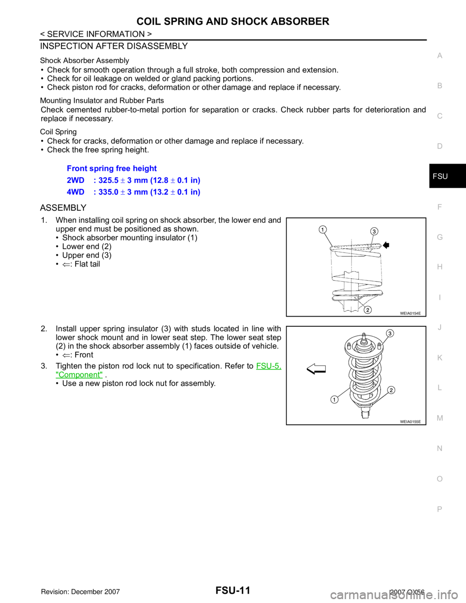
ASSEMBLY
1. When installing coil spring on shock absorber, the lower end and
upper end must be positioned as shown.
• Shock absorber mounting insulator (1)
• Lower end (2)
• Upper end (3)
•⇐: Flat tail
2. Install upper spring insulator (3) with studs located in line with
lower shock mount and in lower seat step. The lower seat step
(2) in the shock absorber assembly (1) faces outside of vehicle.
•⇐: Front
3. Tighten the piston rod lock nut to specification. Refer to FSU-5,
"Component" .
• Use a new piston rod lock nut for assembly.Front spring free height
2WD : 325.5 ± 3 mm (12.8 ± 0.1 in)
4WD : 335.0 ± 3 mm (13.2 ± 0.1 in)
WEIA0154E
WEIA0155E
Page 1964 of 3061
FSU-18
< SERVICE INFORMATION >
KNUCKLE
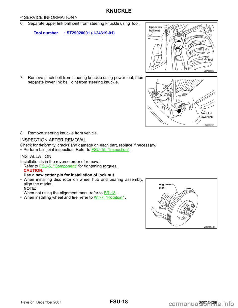
6. Separate upper link ball joint from steering knuckle using Tool.
7. Remove pinch bolt from steering knuckle using power tool, then
separate lower link ball joint from steering knuckle.
8. Remove steering knuckle from vehicle.
INSPECTION AFTER REMOVAL
Check for deformity, cracks and damage on each part, replace if necessary.
• Perform ball joint inspection. Refer to FSU-15, "
Inspection" .
INSTALLATION
Installation is in the reverse order of removal.
• Refer to FSU-5, "
Component" for tightening torques.
CAUTION:
Use a new cotter pin for installation of lock nut.
• When installing disc rotor on wheel hub and bearing assembly,
align the marks.
NOTE:
When not using the alignment mark, refer to BR-18
.
• When installing wheel and tire, refer to WT-7, "
Rotation" . Tool number : ST29020001 (J-24319-01)
LEIA0095E
LEIA0097E
WDIA0044E
Page 1968 of 3061
GI-2
< SERVICE INFORMATION >
PRECAUTIONS
SERVICE INFORMATION
PRECAUTIONS
DescriptionINFOID:0000000003531468
Observe the following precautions to ensure safe and proper servicing. These precautions are not
described in each individual section.
Precaution for Supplemental Restraint System (SRS) "AIR BAG" and "SEAT BELT
PRE-TENSIONER"
INFOID:0000000003531469
The Supplemental Restraint System such as “AIR BAG” and “SEAT BELT PRE-TENSIONER”, used along
with a front seat belt, helps to reduce the risk or severity of injury to the driver and front passenger for certain
types of collision. This system includes seat belt switch inputs and dual stage front air bag modules. The SRS
system uses the seat belt switches to determine the front air bag deployment, and may only deploy one front
air bag, depending on the severity of a collision and whether the front occupants are belted or unbelted.
Information necessary to service the system safely is included in the SRS and SB section of this Service Man-
ual.
WARNING:
• To avoid rendering the SRS inoperative, which could increase the risk of personal injury or death in
the event of a collision which would result in air bag inflation, all maintenance must be performed by
an authorized NISSAN/INFINITI dealer.
• Improper maintenance, including incorrect removal and installation of the SRS, can lead to personal
injury caused by unintentional activation of the system. For removal of Spiral Cable and Air Bag
Module, see the SRS section.
• Do not use electrical test equipment on any circuit related to the SRS unless instructed to in this
Service Manual. SRS wiring harnesses can be identified by yellow and/or orange harnesses or har-
ness connectors.
Precaution for NVIS/IVIS (NISSAN/INFINITI VEHICLE IMMOBILIZER SYSTEM -
NATS) (If Equipped)
INFOID:0000000003531470
NVIS/IVIS (NATS) will immobilize the engine if someone tries to start it without the registered key of NVIS/IVIS
(NATS).
Both of the originally supplied ignition key IDs have been NVIS/IVIS (NATS) registered.
The security indicator is located on the instrument panel. The indicator blinks when the immobilizer system is
functioning.
Therefore, NVIS/IVIS (NATS) warns outsiders that the vehicle is equipped with the anti-theft system.
• When NVIS/IVIS (NATS) detects trouble, the security indicator lamp lights up while ignition switch is in "ON"
position.
This lighting up indicates that the anti-theft is not functioning, so prompt service is required.
• When servicing NVIS/IVIS (NATS) (trouble diagnoses, system initialization and additional registration of
other NVIS/IVIS (NATS) ignition key IDs), CONSULT-II hardware and CONSULT-II NVIS/IVIS (NATS) soft-
ware is necessary.
Regarding the procedures of NVIS/IVIS (NATS) initialization and NVIS/IVIS (NATS) ignition key ID registra-
tion, refer to CONSULT-II operation manual, NVIS/IVIS (NATS).
Therefore, CONSULT-II NVIS/IVIS (NATS) software (program card and operation manual) must be kept
strictly confidential to maintain the integrity of the anti-theft function.
• When servicing NVIS/IVIS (NATS) (trouble diagnoses, system initialization and additional registration of
other NVIS/IVIS (NATS) ignition key IDs), it may be necessary to re-register original key identification.
Therefore, be sure to receive all keys from vehicle owner. A maximum of four or five key IDs can be regis-
tered into NVIS/IVIS (NATS).
• When failing to start the engine first time using the key of NVIS/IVIS (NATS), start as follows.
1. Leave the ignition key in "ON" position for approximately 5 seconds.
2. Turn ignition key to "OFF" or "LOCK" position and wait approximately 5 seconds.
3. Repeat step 1 and 2 again.
4. Restart the engine while keeping the key separate from any others on key-chain.
Page 1969 of 3061
PRECAUTIONS
GI-3
< SERVICE INFORMATION >
C
D
E
F
G
H
I
J
K
L
MB
GI
N
O
P
General PrecautionINFOID:0000000003531471
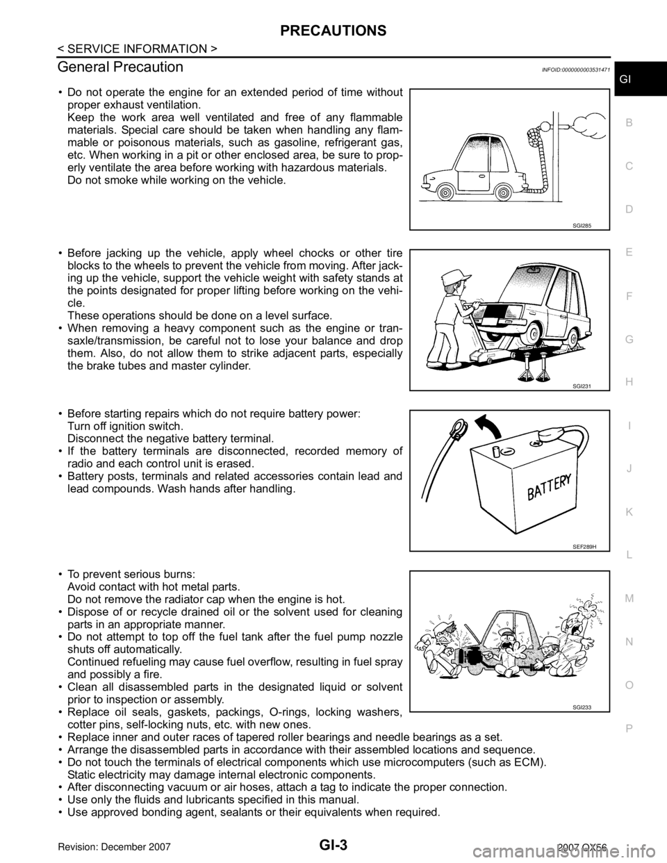
• Do not operate the engine for an extended period of time without
proper exhaust ventilation.
Keep the work area well ventilated and free of any flammable
materials. Special care should be taken when handling any flam-
mable or poisonous materials, such as gasoline, refrigerant gas,
etc. When working in a pit or other enclosed area, be sure to prop-
erly ventilate the area before working with hazardous materials.
Do not smoke while working on the vehicle.
• Before jacking up the vehicle, apply wheel chocks or other tire
blocks to the wheels to prevent the vehicle from moving. After jack-
ing up the vehicle, support the vehicle weight with safety stands at
the points designated for proper lifting before working on the vehi-
cle.
These operations should be done on a level surface.
• When removing a heavy component such as the engine or tran-
saxle/transmission, be careful not to lose your balance and drop
them. Also, do not allow them to strike adjacent parts, especially
the brake tubes and master cylinder.
• Before starting repairs which do not require battery power:
Turn off ignition switch.
Disconnect the negative battery terminal.
• If the battery terminals are disconnected, recorded memory of
radio and each control unit is erased.
• Battery posts, terminals and related accessories contain lead and
lead compounds. Wash hands after handling.
• To prevent serious burns:
Avoid contact with hot metal parts.
Do not remove the radiator cap when the engine is hot.
• Dispose of or recycle drained oil or the solvent used for cleaning
parts in an appropriate manner.
• Do not attempt to top off the fuel tank after the fuel pump nozzle
shuts off automatically.
Continued refueling may cause fuel overflow, resulting in fuel spray
and possibly a fire.
• Clean all disassembled parts in the designated liquid or solvent
prior to inspection or assembly.
• Replace oil seals, gaskets, packings, O-rings, locking washers,
cotter pins, self-locking nuts, etc. with new ones.
• Replace inner and outer races of tapered roller bearings and needle bearings as a set.
• Arrange the disassembled parts in accordance with their assembled locations and sequence.
• Do not touch the terminals of electrical components which use microcomputers (such as ECM).
Static electricity may damage internal electronic components.
• After disconnecting vacuum or air hoses, attach a tag to indicate the proper connection.
• Use only the fluids and lubricants specified in this manual.
• Use approved bonding agent, sealants or their equivalents when required.
SGI285
SGI231
SEF289H
SGI233
Page 1973 of 3061
HOW TO USE THIS MANUAL
GI-7
< SERVICE INFORMATION >
C
D
E
F
G
H
I
J
K
L
MB
GI
N
O
PHOW TO USE THIS MANUAL
DescriptionINFOID:0000000003531478
This volume explains “Removal, Disassembly, Installation, Inspection and Adjustment” and “Trouble Diag-
noses”.
Te r m sINFOID:0000000003531479
• The captions WARNING and CAUTION warn you of steps that must be followed to prevent personal injury
and/or damage to some part of the vehicle.
WARNING indicates the possibility of personal injury if instructions are not followed.
CAUTION indicates the possibility of component damage if instructions are not followed.
BOLD TYPED STATEMENTS except WARNING and CAUTION give you helpful information.
Standard value:Tolerance at inspection and adjustment.
Limit value:The maximum or minimum limit value that should not be exceeded at inspection and adjustment.
UnitsINFOID:0000000003531480
• The UNITS given in this manual are primarily expressed as the SI UNIT (International System of Unit), and
alternatively expressed in the metric system and in the yard/pound system.
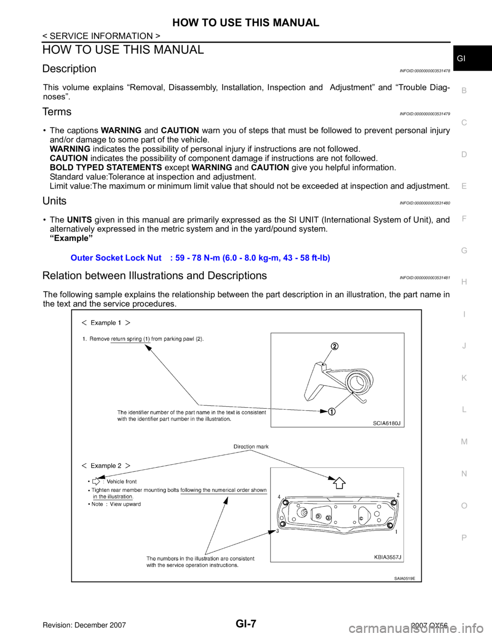
“Example”
Relation between Illustrations and DescriptionsINFOID:0000000003531481
The following sample explains the relationship between the part description in an illustration, the part name in
the text and the service procedures.Outer Socket Lock Nut : 59 - 78 N-m (6.0 - 8.0 kg-m, 43 - 58 ft-lb)
SAIA0519E
Page 1980 of 3061
GI-14
< SERVICE INFORMATION >
HOW TO USE THIS MANUAL
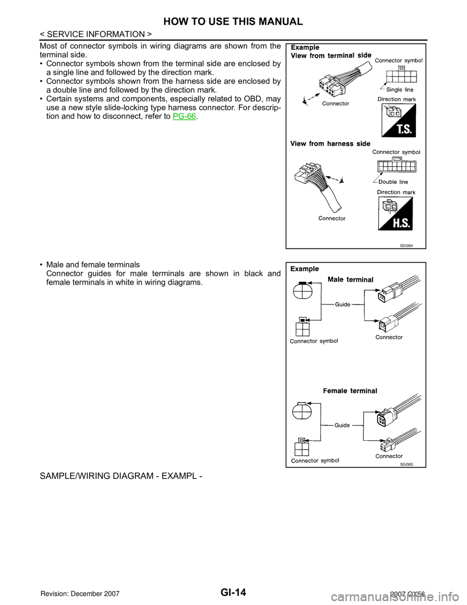
Most of connector symbols in wiring diagrams are shown from the
terminal side.
• Connector symbols shown from the terminal side are enclosed by
a single line and followed by the direction mark.
• Connector symbols shown from the harness side are enclosed by
a double line and followed by the direction mark.
• Certain systems and components, especially related to OBD, may
use a new style slide-locking type harness connector. For descrip-
tion and how to disconnect, refer to PG-66
.
• Male and female terminals
Connector guides for male terminals are shown in black and
female terminals in white in wiring diagrams.
SAMPLE/WIRING DIAGRAM - EXAMPL -
SGI364
SGI363
Page 1990 of 3061
GI-24
< SERVICE INFORMATION >
SERVICE INFORMATION FOR ELECTRICAL INCIDENT
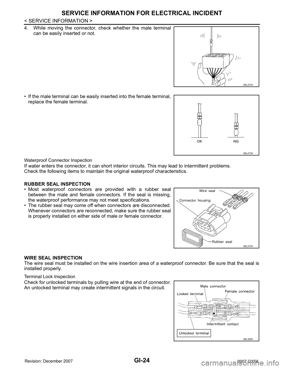
4. While moving the connector, check whether the male terminal
can be easily inserted or not.
• If the male terminal can be easily inserted into the female terminal,
replace the female terminal.
Waterproof Connector Inspection
If water enters the connector, it can short interior circuits. This may lead to intermittent problems.
Check the following items to maintain the original waterproof characteristics.
RUBBER SEAL INSPECTION
• Most waterproof connectors are provided with a rubber seal
between the male and female connectors. If the seal is missing,
the waterproof performance may not meet specifications.
• The rubber seal may come off when connectors are disconnected.
Whenever connectors are reconnected, make sure the rubber seal
is properly installed on either side of male or female connector.
WIRE SEAL INSPECTION
The wire seal must be installed on the wire insertion area of a waterproof connector. Be sure that the seal is
installed properly.
Terminal Lock Inspection
Check for unlocked terminals by pulling wire at the end of connector.
An unlocked terminal may create intermittent signals in the circuit.
SEL272V
SEL273V
SEL275V
SEL330V