2007 INFINITI QX56 stop start
[x] Cancel search: stop startPage 2421 of 3061

IPDM E/R (INTELLIGENT POWER DISTRIBUTION MODULE ENGINE ROOM)
PG-19
< SERVICE INFORMATION >
C
D
E
F
G
H
I
J
L
MA
B
PG
N
O
P
NOTE:
The details for display of the period are as follows:
• CRNT: Error currently detected with IPDM E/R.
• PAST: Error detected in the past and placed in IPDM E/R memory.
DATA MONITOR
All Signals, Main Signals, Selection From Menu
Display itemsCONSULT-II
display codeMalfunction detectionTIME
Possible causes
CRNT PAST
NO DTC IS DETECTED.
FURTHER TESTING
MAY BE REQUIRED.—————
CAN COMM CIRC U1000• If CAN communication reception/transmission
data has a malfunction, or if any of the control
units fail, data reception/transmission cannot
be confirmed.
• When the data in CAN communication is not
received before the specified time.XXAny of items listed be-
low have errors:
• TRANSMIT DIAG
•ECM
•BCM/SEC
ALL SIGNALS All signals will be monitored.
MAIN SIGNALS Monitors the predetermined item(s).
SELECTION FROM MENU Selects and monitors individual signal(s).
Item nameCONSULT-II
screen displayDisplay or unitMonitor item selection
Description
ALL
SIGNALSMAIN
SIGNALSSELECTION
FROM MENU
Motor fan requestMOTOR FAN
REQ1/2/3/4 X X X Signal status input from ECM
Compressor re-
questAC COMP REQ ON/OFF X X X Signal status input from ECM
Parking, license,
and tail lamp re-
questTAIL & CLR REQ ON/OFF X X X Signal status input from BCM
Headlamp low
beam requestHL LO REQ ON/OFF X X X Signal status input from BCM
Headlamp high
beam requestHL HI REQ ON/OFF X X X Signal status input from BCM
Front fog request FR FOG REQ ON/OFF X X X Signal status input from BCM
Front wiper re-
questFR WIP REQSTOP/1LOW/
LOW/HIX X X Signal status input from BCM
Wiper auto stopWIP AUTO
STOPACT P/STOP P X X X Output status of IPDM E/R
Wiper protection WIP PROT OFF/Block X X X Control status of IPDM E/R
Starter request ST RLY REQ ON/OFF X X
Status of input signal
NOTE
Ignition relay
statusIGN RLY ON/OFF X X XIgnition relay status monitored
with IPDM E/R
Rear defogger re-
questRR DEF REQ ON/OFF X X X Signal status input from BCM
Oil pressure
switchOIL P SW (*1) OPEN/CLOSE X XSignal status input from IPDM
E/R
Hood switch HOOD SW OFF XSignal status input from IPDM
E/R
Page 2426 of 3061

PG-24
< SERVICE INFORMATION >
IPDM E/R (INTELLIGENT POWER DISTRIBUTION MODULE ENGINE ROOM)
43 L/Y Wiper auto stop signal InputON or
STARTWiper switch OFF, LO, INT Battery voltage
44 BRDaytime light relay
controlInput ONDaytime light system active 0V
Daytime light system inactive Battery voltage
45 G/W Horn relay control Input ONWhen door locks are operated
using key fob (OFF → ON)*1Battery voltage → 0V
46 GRFuel pump relay con-
trolInput —Ignition switch ON or START 0V
Ignition switch OFF or ACC Battery voltage
47 OThrottle control motor
relay controlInput —Ignition switch ON or START 0V
Ignition switch OFF or ACC Battery voltage
48 B/RStarter relay (inhibit
switch)InputON or
STARTSelector lever in "P" or "N" 0V
Selector lever any other posi-
tionBattery voltage
49 R/L Trailer tow relay Output ONLighting
switch must
be in the 1st
positionOFF 0V
ON Battery voltage
50 W/R Front fog lamp (LH) OutputON or
STARTLighting
switch must
be in the 2nd
position
(LOW beam
is ON) and
the front fog
lamp switchOFF 0V
ON Battery voltage
51 W/R Front fog lamp (RH) OutputON or
STARTLighting
switch must
be in the 2nd
position
(LOW beam
is ON) and
the front fog
lamp switchOFF 0V
ON Battery voltage
52 LLH low beam head-
lampOutput — Lighting switch in 2nd position Battery voltage
54 R/YRH low beam head-
lampOutput — Lighting switch in 2nd position Battery voltage
55 GLH high beam head-
lampOutput —Lighting switch in 2nd position
and placed in HIGH or PASS
positionBattery voltage
56L/W*2
Y*3LH high beam head-
lampOutput —Lighting switch in 2nd position
and placed in HIGH or PASS
positionBattery voltage
57 R/LParking, license, and
tail lampOutput ONLighting
switch 1st po-
sitionOFF 0V
ON Battery voltage
59 B Ground Input — — 0V
60 B/WRear window defog-
ger relayOutputON or
STARTRear defogger switch ON Battery voltage
Rear defogger switch OFF 0V Te r m i n a lWire
colorSignal nameSignal
input/
outputMeasuring condition
Reference value
(Approx.) Igni-
tion
switchOperation or condition
Page 2463 of 3061

HARNESS
PG-61
< SERVICE INFORMATION >
C
D
E
F
G
H
I
J
L
MA
B
PG
N
O
P
ICC/BS EC ICC Steering Switch
ICC/SW EC ICC Brake Switch
I/MIRR GW Inside Mirror (Auto Anti-Dazzling Mirror)
IATS EC Intake Air Temperature Sensor
IGNSYS EC Ignition System
ILL LT Illumination
INJECT EC Injector
INT/L LT Room/Map, Vanity, Cargo, Personal, Foot, Step, and Puddle Lamps
KEYLES BL Remote Keyless Entry System
KS EC Knock Sensor
MAFS EC Mass Air Flow Sensor
MAIN EC Main Power Supply and Ground Circuit
METER DI Speedometer, Tachometer, Temp. and Fuel Gauges
MIL/DL EC Malfunction Indicator Lamp
MIRROR GW Door Mirror
NATS BL Nissan Anti-Theft System
NAVI AV Navigation System
O2H2B1 EC Rear Heated Oxygen Sensor 2 Heater Bank 1
O2H2B2 EC Rear Heated Oxygen Sensor 2 Heater Bank 2
O2S2B1 EC Heated Oxygen Sensor 2 Bank 1
O2S2B2 EC Heated Oxygen Sensor 2 Bank 2
P/SCKT WW Power Socket
PGC/V EC EVAP Canister Purge Volume Control Solenoid Valve
PHASE EC Camshaft Position Sensor (PHASE) (Bank 1)
PNP/SW EC Park/Neutral Position Switch
POS EC Crankshaft Position Sensor (POS)
POWER PG Power Supply Routing
PRE/SE EC EVAP Control System Pressure Sensor
PS/SEN EC Power Steering Pressure Sensor
R/VIEW DI Rear View Monitor
RP/SEN EC Refrigerant Pressure Sensor
SEN/PW EC Sensor Power Supply
SHIFT AT A/T Shift Lock System
SONAR DI Rear Sonar System
SROOF RF Sunroof
SRS SRS Supplemental Restraint System
START SC Starting System
STOP/L LT Stop Lamp
T/TOW LT Trailer Tow
T/WARN WT Low Tire Pressure Warning System
TAIL/L LT Parking, License and Tail Lamps
T/F TF Transfer Case
TPS1 EC Throttle Position Sensor
TPS2 EC Throttle Position Sensor
TPS3 EC Throttle Position Sensor
TRNSCV BL HOMELINK® Universal Transceiver
TURN LT Turn Signal and Hazard Warning Lamps
VDC BRC Vehicle Dynamic Control System
VEHSEC BL Vehicle security (theft warning) system
VENT/V EC EVAP Canister Vent Control Valve
W/ANT AV Audio Antenna
WARN DI Warning Lamps
Page 2538 of 3061

RF-6
< SERVICE INFORMATION >
SQUEAK AND RATTLE TROUBLE DIAGNOSIS
Insulates where slight movement is present. Ideal for instrument panel applications.
SILICONE GREASE
Used in place of UHMW tape that will be visible or not fit.
Note: Will only last a few months.
SILICONE SPRAY
Use when grease cannot be applied.
DUCT TAPE
Use to eliminate movement.
CONFIRM THE REPAIR
Confirm that the cause of a noise is repaired by test driving the vehicle. Operate the vehicle under the same
conditions as when the noise originally occurred. Refer to the notes on the Diagnostic Worksheet.
Generic Squeak and Rattle TroubleshootingINFOID:0000000003533093
Refer to Table of Contents for specific component removal and installation information.
INSTRUMENT PANEL
Most incidents are caused by contact and movement between:
1. The cluster lid A and instrument panel
2. Acrylic lens and combination meter housing
3. Instrument panel to front pillar garnish
4. Instrument panel to windshield
5. Instrument panel pins
6. Wiring harnesses behind the combination meter
7. A/C defroster duct and duct joint
These incidents can usually be located by tapping or moving the components to duplicate the noise or by
pressing on the components while driving to stop the noise. Most of these incidents can be repaired by apply-
ing felt cloth tape or silicone spray (in hard to reach areas). Urethane pads can be used to insulate wiring har-
ness.
CAUTION:
Do not use silicone spray to isolate a squeak or rattle. If you saturate the area with silicone, you will
not be able to recheck the repair.
CENTER CONSOLE
Components to pay attention to include:
1. Shifter assembly cover to finisher
2. A/C control unit and cluster lid C
3. Wiring harnesses behind audio and A/C control unit
The instrument panel repair and isolation procedures also apply to the center console.
DOORS
Pay attention to the:
1. Finisher and inner panel making a slapping noise
2. Inside handle escutcheon to door finisher
3. Wiring harnesses tapping
4. Door striker out of alignment causing a popping noise on starts and stops
Tapping or moving the components or pressing on them while driving to duplicate the conditions can isolate
many of these incidents. You can usually insulate the areas with felt cloth tape or insulator foam blocks from
the NISSAN Squeak and Rattle Kit (J-43980) to repair the noise.
TRUNK
Trunk noises are often caused by a loose jack or loose items put into the trunk by the owner.
In addition look for:
1. Trunk lid bumpers out of adjustment
2. Trunk lid striker out of adjustment
3. The trunk lid torsion bars knocking together
4. A loose license plate or bracket
Page 2565 of 3061

RFD-8
< SERVICE INFORMATION >
DIFFERENTIAL GEAR OIL
DIFFERENTIAL GEAR OIL
Changing Differential Gear OilINFOID:0000000003532601
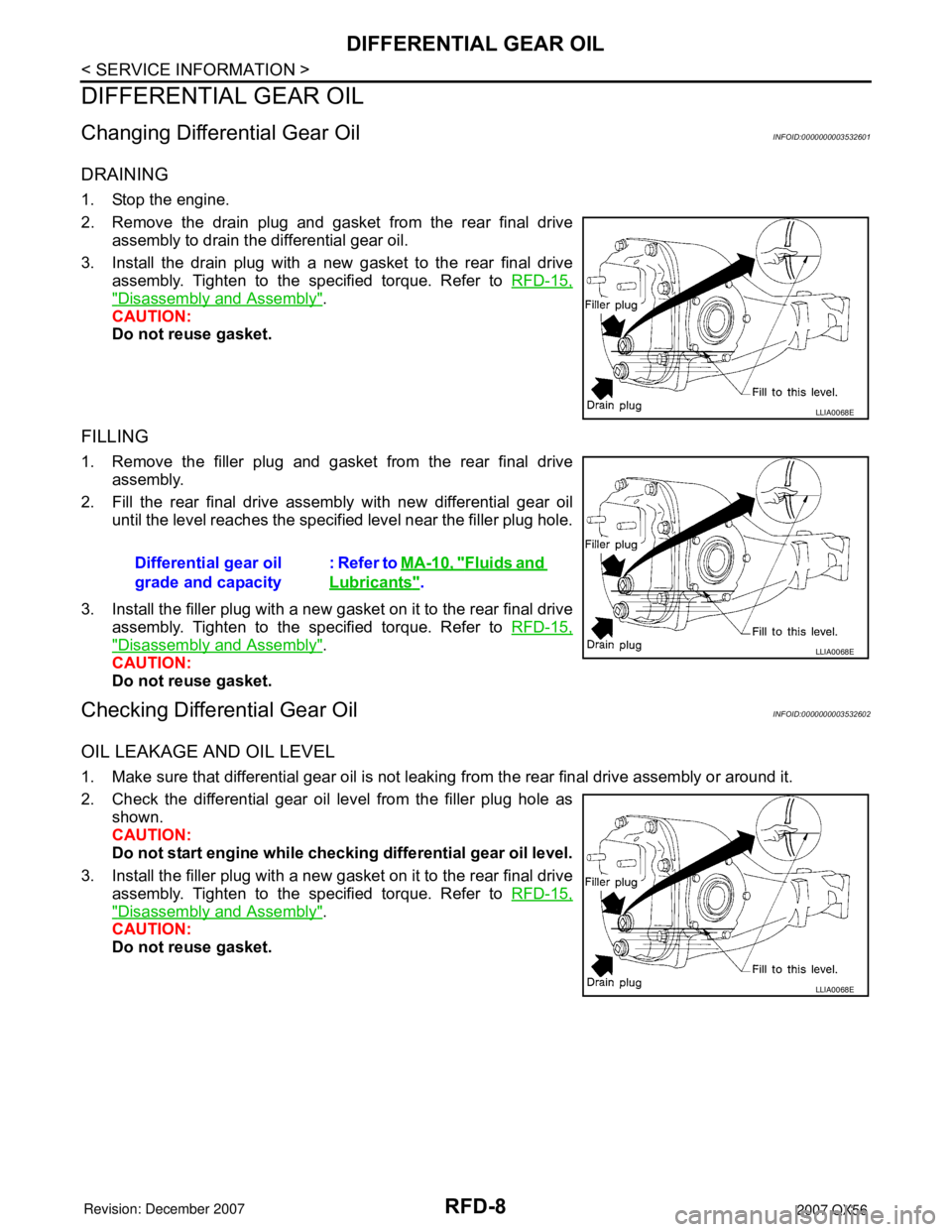
DRAINING
1. Stop the engine.
2. Remove the drain plug and gasket from the rear final drive
assembly to drain the differential gear oil.
3. Install the drain plug with a new gasket to the rear final drive
assembly. Tighten to the specified torque. Refer to RFD-15,
"Disassembly and Assembly".
CAUTION:
Do not reuse gasket.
FILLING
1. Remove the filler plug and gasket from the rear final drive
assembly.
2. Fill the rear final drive assembly with new differential gear oil
until the level reaches the specified level near the filler plug hole.
3. Install the filler plug with a new gasket on it to the rear final drive
assembly. Tighten to the specified torque. Refer to RFD-15,
"Disassembly and Assembly".
CAUTION:
Do not reuse gasket.
Checking Differential Gear OilINFOID:0000000003532602
OIL LEAKAGE AND OIL LEVEL
1. Make sure that differential gear oil is not leaking from the rear final drive assembly or around it.
2. Check the differential gear oil level from the filler plug hole as
shown.
CAUTION:
Do not start engine while checking differential gear oil level.
3. Install the filler plug with a new gasket on it to the rear final drive
assembly. Tighten to the specified torque. Refer to RFD-15,
"Disassembly and Assembly".
CAUTION:
Do not reuse gasket.
LLIA0068E
Differential gear oil
grade and capacity: Refer to MA-10, "Fluids and
Lubricants".
LLIA0068E
LLIA0068E
Page 2603 of 3061

TROUBLE DIAGNOSIS
RSU-13
< SERVICE INFORMATION >
C
D
F
G
H
I
J
K
L
MA
B
RSU
N
O
P
X: Applicable
–: Not applicable
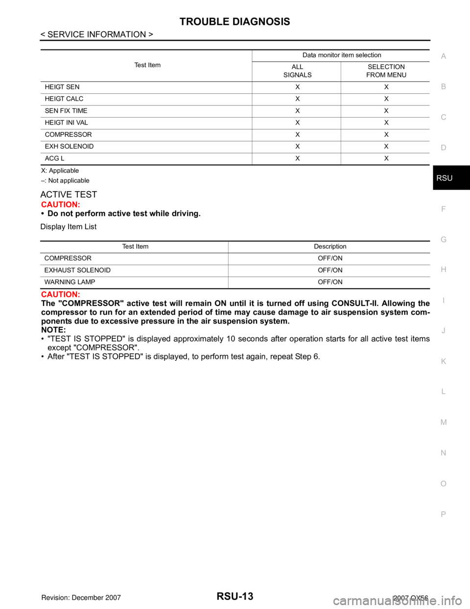
ACTIVE TEST
CAUTION:
• Do not perform active test while driving.
Display Item List
CAUTION:
The "COMPRESSOR" active test will remain ON until it is turned off using CONSULT-II. Allowing the
compressor to run for an extended period of time may cause damage to air suspension system com-
ponents due to excessive pressure in the air suspension system.
NOTE:
• "TEST IS STOPPED" is displayed approximately 10 seconds after operation starts for all active test items
except "COMPRESSOR".
• After "TEST IS STOPPED" is displayed, to perform test again, repeat Step 6.
Test ItemData monitor item selection
ALL
SIGNALSSELECTION
FROM MENU
HEIGT SENXX
HEIGT CALCXX
SEN FIX TIME X X
HEIGT INI VAL X X
COMPRESSOR X X
EXH SOLENOID X X
ACG LXX
Test Item Description
COMPRESSOROFF/ON
EXHAUST SOLENOID OFF/ON
WARNING LAMPOFF/ON
Page 2654 of 3061

SC-6
< SERVICE INFORMATION >
BATTERY
CHARGING THE BATTERY
CAUTION:
• Do not “quick charge” a fully discharged battery.
• Keep the battery away from open flame while it is being charged.
• When connecting the charger, connect the leads first, then turn on the charger. Do not turn on the
charger first, as this may cause a spark.
• If battery electrolyte temperature rises above 55°C (131°F), stop charging. Always charge battery at a
temperature below 55°C (131°F).
Charging Rates
Do not charge at more than 50 ampere rate.
NOTE:
The ammeter reading on your battery charger will automatically decrease as the battery charges. This indi-
cates that the voltage of the battery is increasing normally as the state of charge improves. The charging amps
indicated above refer to initial charge rate.
• If, after charging, the specific gravity of any two cells varies more than 0.050, the battery should be replaced.
Trouble Diagnosis with Battery/Starting/Charging System TesterINFOID:0000000003533317
CAUTION:
When working with batteries, always wear appropriate eye protection.
NOTE:
• To ensure a complete and thorough diagnosis, the battery, starter and generator test segments must be
done as a set from start to finish.
• If battery surface charge is detected while testing, the tester will prompt you to turn on the headlights to
remove the surface charge.
• If necessary, the tester will prompt you to determine if the battery temperature is above or below 0°C (32°F).
Choose the appropriate selection by pressing the up or down arrow button, then press “ENTER” to make the
selection.
−7 (20)−0.024
−12 (10)−0.028
−18 (0)−0.032
Corrected specific gravity Approximate charge condition
1.260 - 1.280 Fully charged
1.230 - 1.250 3/4 charged
1.200 - 1.220 1/2 charged
1.170 - 1.190 1/4 charged
1.140 - 1.160 Almost discharged
1.110 - 1.130 Completely discharged Battery electrolyte temperature °C (°F) Add to specific gravity reading
Amps Time
50 1 hour
25 2 hours
10 5 hours
5 10 hours
Page 2666 of 3061

SC-18
< SERVICE INFORMATION >
CHARGING SYSTEM
Before starting, perform the preliminary inspection. Refer to "PRELIMINARY INSPECTION".
1. Stop the operation of the power generation variable voltage control system using either of the following
procedures.
• Using the CONSULT-II, select "ENGINE" from "SELECT SYSTEM" and set the "ALT DUTY" to 0%.
Keep "ALT DUTY" at 0% until the end of the inspection. When the "ALT DUTY" value is 0% or 100%,
normal power generation is performed according to the characteristic of the IC regulator in the genera-
tor.
• Turn the ignition switch off, and disconnect the battery current sensor connector. Disconnecting the bat-
tery current sensor may cause DTC (P1550 - P1554) to set. After finishing the inspection, connect the
battery current sensor connector and erase the self-diagnostic results history of the engine using CON-
SULT-II.
2. Turn off all loads on the vehicle electrical system.
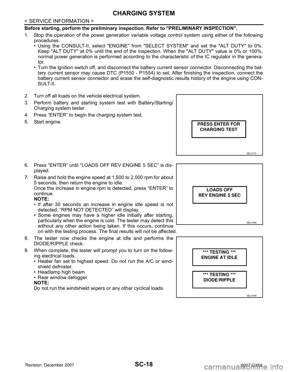
3. Perform battery and starting system test with Battery/Starting/
Charging system tester.
4. Press “ENTER” to begin the charging system test.
5. Start engine.
6. Press “ENTER” until “LOADS OFF REV ENGINE 5 SEC” is dis-
played.
7. Raise and hold the engine speed at 1,500 to 2,000 rpm for about
5 seconds, then return the engine to idle.
Once the increase in engine rpm is detected, press “ENTER” to
continue.
NOTE:
• If after 30 seconds an increase in engine idle speed is not
detected, “RPM NOT DETECTED” will display.
• Some engines may have a higher idle initially after starting,
particularly when the engine is cold. The tester may detect this
without any other action being taken. If this occurs, continue
on with the testing process. The final results will not be affected.
8. The tester now checks the engine at idle and performs the
DIODE/RIPPLE check.
9. When complete, the tester will prompt you to turn on the follow-
ing electrical loads.
• Heater fan set to highest speed. Do not run the A/C or wind-
shield defroster.
• Headlamp high beam
• Rear window defogger
NOTE:
Do not run the windshield wipers or any other cyclical loads.
SEL417X
SEL418X
SEL419X