2007 INFINITI QX56 stop start
[x] Cancel search: stop startPage 2672 of 3061

SC-24
< SERVICE INFORMATION >
SERVICE DATA AND SPECIFICATIONS (SDS)
SERVICE DATA AND SPECIFICATIONS (SDS)
BatteryINFOID:0000000003533327
StarterINFOID:0000000003533328
GeneratorINFOID:0000000003533329
Ty p eGr. 27
Capacity (20 HR) minimum 12V - 80AH
Cold cranking current A
(For reference value)710
ApplicationAll models
ManufacturerMitsubishi
M002T85571ZCKD
Ty p eReduction gear type
System voltage 12V
No-loadTerminal voltage 11V
Current Less than 145A
Revolution More than 3,300 rpm
Minimum diameter of commutator 31.4 mm (1.236 in)
Minimum length of brush 11.0 mm (0.433 in)
Brush spring tension 26.7 - 36.1 N (2.72 - 3.68 kg, 5.93 - 8.02 lb)
Clearance between pinion front edge and
pinion stopper0.5 - 2.0 mm (0.020 - 0.079 in)
Ty p eTG15C13
Va l e o
Nominal rating14V - 130A
Ground polarityNegative
Minimum revolution under no-load 1,200 rpm
Hot output current (When 13.5 volts is applied)More than 52A/1,500 rpm
More than 82A/1,800 rpm
More than 115A/2,500 rpm
More than 130A/5,000 rpm
Regulated output voltage 13.5V @ 5,000 rpm @ 20°C
Adjustment range of power generation variable voltage control 11.4-15.6V
Page 2679 of 3061
SQUEAK AND RATTLE TROUBLE DIAGNOSIS
SE-7
< SERVICE INFORMATION >
C
D
E
F
G
H
J
K
L
MA
B
SE
N
O
P
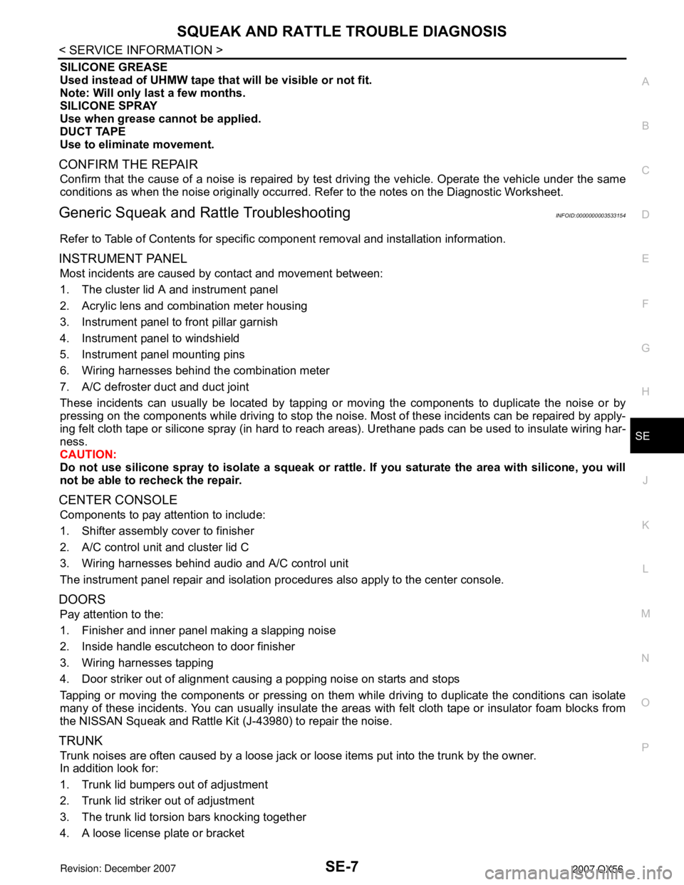
SILICONE GREASE
Used instead of UHMW tape that will be visible or not fit.
Note: Will only last a few months.
SILICONE SPRAY
Use when grease cannot be applied.
DUCT TAPE
Use to eliminate movement.
CONFIRM THE REPAIR
Confirm that the cause of a noise is repaired by test driving the vehicle. Operate the vehicle under the same
conditions as when the noise originally occurred. Refer to the notes on the Diagnostic Worksheet.
Generic Squeak and Rattle TroubleshootingINFOID:0000000003533154
Refer to Table of Contents for specific component removal and installation information.
INSTRUMENT PANEL
Most incidents are caused by contact and movement between:
1. The cluster lid A and instrument panel
2. Acrylic lens and combination meter housing
3. Instrument panel to front pillar garnish
4. Instrument panel to windshield
5. Instrument panel mounting pins
6. Wiring harnesses behind the combination meter
7. A/C defroster duct and duct joint
These incidents can usually be located by tapping or moving the components to duplicate the noise or by
pressing on the components while driving to stop the noise. Most of these incidents can be repaired by apply-
ing felt cloth tape or silicone spray (in hard to reach areas). Urethane pads can be used to insulate wiring har-
ness.
CAUTION:
Do not use silicone spray to isolate a squeak or rattle. If you saturate the area with silicone, you will
not be able to recheck the repair.
CENTER CONSOLE
Components to pay attention to include:
1. Shifter assembly cover to finisher
2. A/C control unit and cluster lid C
3. Wiring harnesses behind audio and A/C control unit
The instrument panel repair and isolation procedures also apply to the center console.
DOORS
Pay attention to the:
1. Finisher and inner panel making a slapping noise
2. Inside handle escutcheon to door finisher
3. Wiring harnesses tapping
4. Door striker out of alignment causing a popping noise on starts and stops
Tapping or moving the components or pressing on them while driving to duplicate the conditions can isolate
many of these incidents. You can usually insulate the areas with felt cloth tape or insulator foam blocks from
the NISSAN Squeak and Rattle Kit (J-43980) to repair the noise.
TRUNK
Trunk noises are often caused by a loose jack or loose items put into the trunk by the owner.
In addition look for:
1. Trunk lid bumpers out of adjustment
2. Trunk lid striker out of adjustment
3. The trunk lid torsion bars knocking together
4. A loose license plate or bracket
Page 2684 of 3061

SE-12
< SERVICE INFORMATION >
AUTOMATIC DRIVE POSITIONER
NOTE:
• Disconnecting the battery erases the stored memory.
• After connecting the battery, insert the key into the ignition cylinder and turn the front door switch LH ON (open)→OFF (close)→ON
(open), the entry/exiting function becomes possible.
• After Exiting operation is carried out, return operation can be operated.
NOTE:
During automatic operation, if the ignition switch is turned ON→START, the automatic operation is suspended. When the ignition switch
returns to ON, it resumes.
FA I L - S A F E M O D E
When any manual and automatic operations are not performed, if any motor operations of seats or pedals are
detected for T2 or more, status is judged “Output error”.
CANCEL OF FAIL-SAFE MODE
The mode is cancelled when the A/T selector lever is shifted to P position from any other position.
NOTE:
The front seat LH position and pedal adjustment functions (see the following table) operate simultaneously in
the order of priority.
*: In conjunction with sliding the seat, the door mirrors are positioned.Function Description
Memory operation The front seat LH, steering wheel, pedals (accelerator, brake) and door mirrors move
to the stored driving position by pushing seat memory switch (1 or 2).
Entry/exit-
ing functionExiting operation At exit, the seat moves backward and the steering wheel raises. (Exiting position)
Entry operationAt entry, the seat and steering wheel return from exiting position to the previous driving
position before the exiting operation.
Keyfob interlock operationPerform memory operation, turnout operation and return operation by pressing keyfob
unlock button.
Auto operation temporary stop
conditions.When ignition switch is turned to START during seat memory switch operation and return
operation, seat memory switch operation and return operation is stopped.
Auto operation stop conditions.• When the vehicle speed becomes 7 km/h (4 MPH) or higher (memory switch operation
and entry operation).
• When the setting switch, seat memory switch 1, or 2 are pressed.
• When A/T selector lever is in any position other than P.
• When the door mirror remote control switch is operated (when ignition switch turned to
ON).
• When power seat switch turned ON.
• When pedal adjusting switch turned ON.
• When front seat sliding entry/exiting setting is OFF (entry/exiting operation).
OPERATED PORTION T2
Seat sliding Approx. 0.1 sec.
Seat reclining Same as above
Seat lifting (Front) Same as above
Seat lifting (Rear) Same as above
Steering wheel Same as above
Pedal adjust Same as above
Priority Function Priority Function
1 Seat sliding, (door mirror LH/RH)* 4 Seat reclining
2 Pedal 5 Seat lifter-FR
3 Steering wheel 6 Seat lifter-RR
Page 2825 of 3061
PRECAUTIONS
TF-3
< SERVICE INFORMATION >
C
E
F
G
H
I
J
K
L
MA
B
TF
N
O
P
SERVICE INFORMATION
PRECAUTIONS
Precaution for Supplemental Restraint System (SRS) "AIR BAG" and "SEAT BELT
PRE-TENSIONER"
INFOID:0000000003532506
The Supplemental Restraint System such as “AIR BAG” and “SEAT BELT PRE-TENSIONER”, used along
with a front seat belt, helps to reduce the risk or severity of injury to the driver and front passenger for certain
types of collision. This system includes seat belt switch inputs and dual stage front air bag modules. The SRS
system uses the seat belt switches to determine the front air bag deployment, and may only deploy one front
air bag, depending on the severity of a collision and whether the front occupants are belted or unbelted.
Information necessary to service the system safely is included in the SRS and SB section of this Service Man-
ual.
WARNING:
• To avoid rendering the SRS inoperative, which could increase the risk of personal injury or death in
the event of a collision which would result in air bag inflation, all maintenance must be performed by
an authorized NISSAN/INFINITI dealer.
• Improper maintenance, including incorrect removal and installation of the SRS, can lead to personal
injury caused by unintentional activation of the system. For removal of Spiral Cable and Air Bag
Module, see the SRS section.
• Do not use electrical test equipment on any circuit related to the SRS unless instructed to in this
Service Manual. SRS wiring harnesses can be identified by yellow and/or orange harnesses or har-
ness connectors.
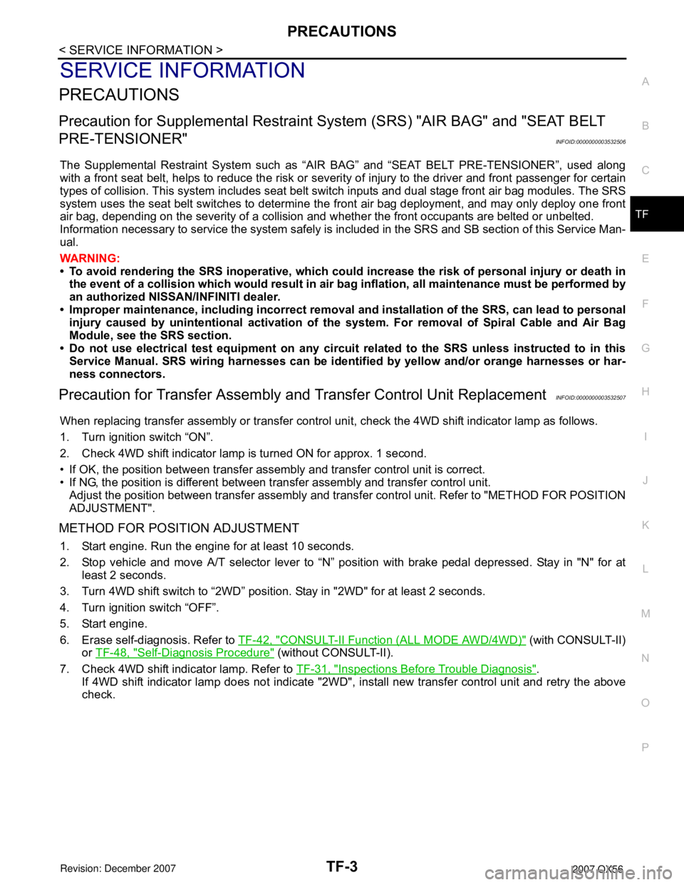
Precaution for Transfer Assembly and Transfer Control Unit ReplacementINFOID:0000000003532507
When replacing transfer assembly or transfer control unit, check the 4WD shift indicator lamp as follows.
1. Turn ignition switch “ON”.
2. Check 4WD shift indicator lamp is turned ON for approx. 1 second.
• If OK, the position between transfer assembly and transfer control unit is correct.
• If NG, the position is different between transfer assembly and transfer control unit.
Adjust the position between transfer assembly and transfer control unit. Refer to "METHOD FOR POSITION
ADJUSTMENT".
METHOD FOR POSITION ADJUSTMENT
1. Start engine. Run the engine for at least 10 seconds.
2. Stop vehicle and move A/T selector lever to “N” position with brake pedal depressed. Stay in "N" for at
least 2 seconds.
3. Turn 4WD shift switch to “2WD” position. Stay in "2WD" for at least 2 seconds.
4. Turn ignition switch “OFF”.
5. Start engine.
6. Erase self-diagnosis. Refer to TF-42, "
CONSULT-II Function (ALL MODE AWD/4WD)" (with CONSULT-II)
or TF-48, "
Self-Diagnosis Procedure" (without CONSULT-II).
7. Check 4WD shift indicator lamp. Refer to TF-31, "
Inspections Before Trouble Diagnosis".
If 4WD shift indicator lamp does not indicate "2WD", install new transfer control unit and retry the above
check.
Page 2833 of 3061
TRANSFER FLUID
TF-11
< SERVICE INFORMATION >
C
E
F
G
H
I
J
K
L
MA
B
TF
N
O
P
TRANSFER FLUID
ReplacementINFOID:0000000003532513
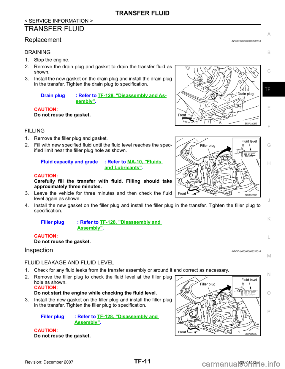
DRAINING
1. Stop the engine.
2. Remove the drain plug and gasket to drain the transfer fluid as
shown.
3. Install the new gasket on the drain plug and install the drain plug
in the transfer. Tighten the drain plug to specification.
CAUTION:
Do not reuse the gasket.
FILLING
1. Remove the filler plug and gasket.
2. Fill with new specified fluid until the fluid level reaches the spec-
ified limit near the filler plug hole as shown.
CAUTION:
Carefully fill the transfer with fluid. Filling should take
approximately three minutes.
3. Leave the vehicle for three minutes and then check the fluid
level again as shown.
4. Install the new gasket on the filler plug and install the filler plug in the transfer. Tighten the filler plug to
specification.
CAUTION:
Do not reuse the gasket.
InspectionINFOID:0000000003532514
FLUID LEAKAGE AND FLUID LEVEL
1. Check for any fluid leaks from the transfer assembly or around it and correct as necessary.
2. Remove the filler plug to check the fluid level at the filler plug
hole as shown.
CAUTION:
Do not start the engine while checking the fluid level.
3. Install the new gasket on the filler plug and install the filler plug
in the transfer. Tighten the filler plug to specification.
CAUTION:
Do not reuse the gasket.Drain plug : Refer to TF-128, "
Disassembly and As-
sembly".
SDIA3208E
Fluid capacity and grade : Refer to MA-10, "Fluids
and Lubricants".
Filler plug : Refer to TF-128, "
Disassembly and
Assembly".
SDIA3209E
Filler plug : Refer to TF-128, "Disassembly and
Assembly".
SDIA3209E
Page 2840 of 3061

TF-18
< SERVICE INFORMATION >
ALL-MODE 4WD SYSTEM
LINE PRESSURE SWITCH
• With the transfer system design, control of the oil pressure provides the transmission of drive torque to the
front wheels. The main pressure to control the oil pressure is referred to as the line pressure.
• The line pressure switch determines whether or not adequate line pressure has built up under different oper-
ating conditions.
• The line pressure switch turns ON when line pressure is produced.
• The line pressure switch senses line pressure abnormalities and turns the 4WD warning lamp ON.
CLUTCH PRESSURE SWITCH
• The clutch pressure switch determines whether or not adequate clutch pressure has built up under different
operating conditions.
• The clutch pressure switch turns ON when clutch pressure is produced.
• The clutch pressure switch senses clutch pressure abnormalities and turns the 4WD warning lamp ON.
TRANSFER FLUID TEMPERATURE SENSOR
The transfer temperature sensor detects the transfer fluid temperature and sends a signal to the transfer con-
trol unit.
TRANSFER CONTROL UNIT
• Transfer control unit controls transfer control device by input signals of each sensor and each switch.
• Self-diagnosis can be done.
TRANSFER CONTROL DEVICE
The transfer control device changes the state of transfer assembly between 2WD, AUTO, 4H⇔4LO with the
2WD, AUTO, 4H and 4LO signals of 4WD shift switch.
NOTE:
• To shift between 4H⇔4LO, stop the vehicle, depress the brake pedal and shift the transmission selector to
the "N" position. Depress and turn the 4WD shift switch. The shift switch will not shift to the desired mode if
the transmission is not in "N" or the vehicle is moving. The 4LO indicator lamp will be lit when the 4LO is
engaged.
• Actuator motor and actuator position switch are integrated.
4WD SHIFT SWITCH AND INDICATOR LAMP
4WD Shift Switch
The 4WD shift switch allows selection from 2WD, AUTO, 4H or 4LO.
4WD Shift Indicator Lamp
• Displays driving conditions selected by 4WD shift switch with 2WD, AUTO and 4H indicators while engine is
running. (When 4WD warning lamp is turned on, all 4WD shift indicator lamps are turned off.)
• Turns ON for approximately 1 second when ignition switch is turned ON, for purpose of lamp check.
4LO Indicator Lamp
• Displays 4LO condition while engine is running. 4LO indicator lamp flashes if transfer gear does not shift
completely under 2WD, AUTO, 4H⇔4LO. (When 4WD warning lamp is turned on, 4LO indicator lamp is
turned off.)
• Turns ON for approximately 1 second when ignition switch is turned ON, for purpose of lamp check.
4WD WARNING LAMP
Turns ON or FLASH when there is a malfunction in 4WD system.
Also turns ON when ignition switch is turned ON, for purpose of lamp check. Turns OFF for approximately 1
second after the engine starts if system is normal.
4WD Warning Lamp Indication
Condition Content 4WD warning lamp
During self-diagnosis Indicates the malfunction position by number of flickers. Flickers at malfunction mode.
Lamp check*Checks the lamp by turning ON during engine starting. After
engine starts, it turns OFF if there are no malfunctions.ON
Malfunction in 4WD system*Turns ON to indicate malfunction. When ignition switch is
turned to “OFF” or the malfunction is corrected, it turns OFF.ON
When vehicle is driven with different
diameters of front and rear tiresFlickers once every 2 seconds.
Turns OFF when ignition switch is “OFF”.Flickers once every 2 sec-
onds.
Page 2877 of 3061
TROUBLE DIAGNOSIS FOR SYSTEM
TF-55
< SERVICE INFORMATION >
C
E
F
G
H
I
J
K
L
MA
B
TF
N
O
P
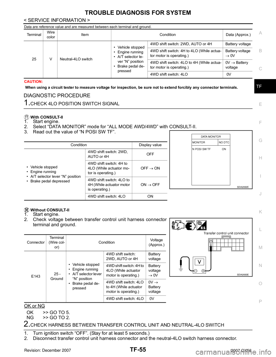
Data are reference value and are measured between each terminal and ground.
CAUTION:
When using a circuit tester to measure voltage for inspection, be sure not to extend forcibly any connector terminals.
DIAGNOSTIC PROCEDURE
1.CHECK 4LO POSITION SWITCH SIGNAL
With CONSULT-II
1. Start engine.
2. Select “DATA MONITOR” mode for “ALL MODE AWD/4WD” with CONSULT-II.
3. Read out the value of “N POSI SW TF”.
Without CONSULT-II
1. Start engine.
2. Check voltage between transfer control unit harness connector
terminal and ground.
OK or NG
OK >> GO TO 5.
NG >> GO TO 2.
2.CHECK HARNESS BETWEEN TRANSFER CONTROL UNIT AND NEUTRAL-4LO SWITCH
1. Turn ignition switch “OFF”. (Stay for at least 5 seconds.)
2. Disconnect transfer control unit harness connector and the neutral-4LO switch harness connector.
Te r m i n a lWire
colorItem Condition Data (Approx.)
25 V Neutral-4LO switch• Vehicle stopped
• Engine running
• A/T selector le-
ver “N” position
• Brake pedal de-
pressed4WD shift switch: 2WD, AUTO or 4H Battery voltage
4WD shift switch: 4H to 4LO (While actua-
tor motor is operating.)Battery voltage
→ 0V
4WD shift switch: 4LO to 4H (While actua-
tor motor is operating.)0V → Battery
voltage
4WD shift switch: 4LO 0V
Condition Display value
• Vehicle stopped
• Engine running
• A/T selector lever “N” position
• Brake pedal depressed4WD shift switch: 2WD,
AUTO or 4HOFF
4WD shift switch: 4H to
4LO (While actuator mo-
tor is operating.)OFF → ON
4WD shift switch: 4LO to
4H (While actuator motor
is operating.)ON → OFF
4WD shift switch: 4LO ON
SDIA2692E
ConnectorTe r m i n a l
(Wire col-
or)ConditionVoltage
(Approx.)
E143 25 -
Ground• Vehicle stopped
• Engine running
• A/T selector lever
“N” position
• Brake pedal de-
pressed4WD shift switch:
2WD, AUTO or 4HBattery
voltage
4WD shift switch: 4H to
4LO (While actuator
motor is operating.)Battery
voltage
→ 0V
4WD shift switch: 4LO
to 4H (While actuator
motor is operating.)0V →
Battery
voltage
4WD shift switch: 4LO 0V
SDIA2693E
Page 2879 of 3061
TROUBLE DIAGNOSIS FOR SYSTEM
TF-57
< SERVICE INFORMATION >
C
E
F
G
H
I
J
K
L
MA
B
TF
N
O
P
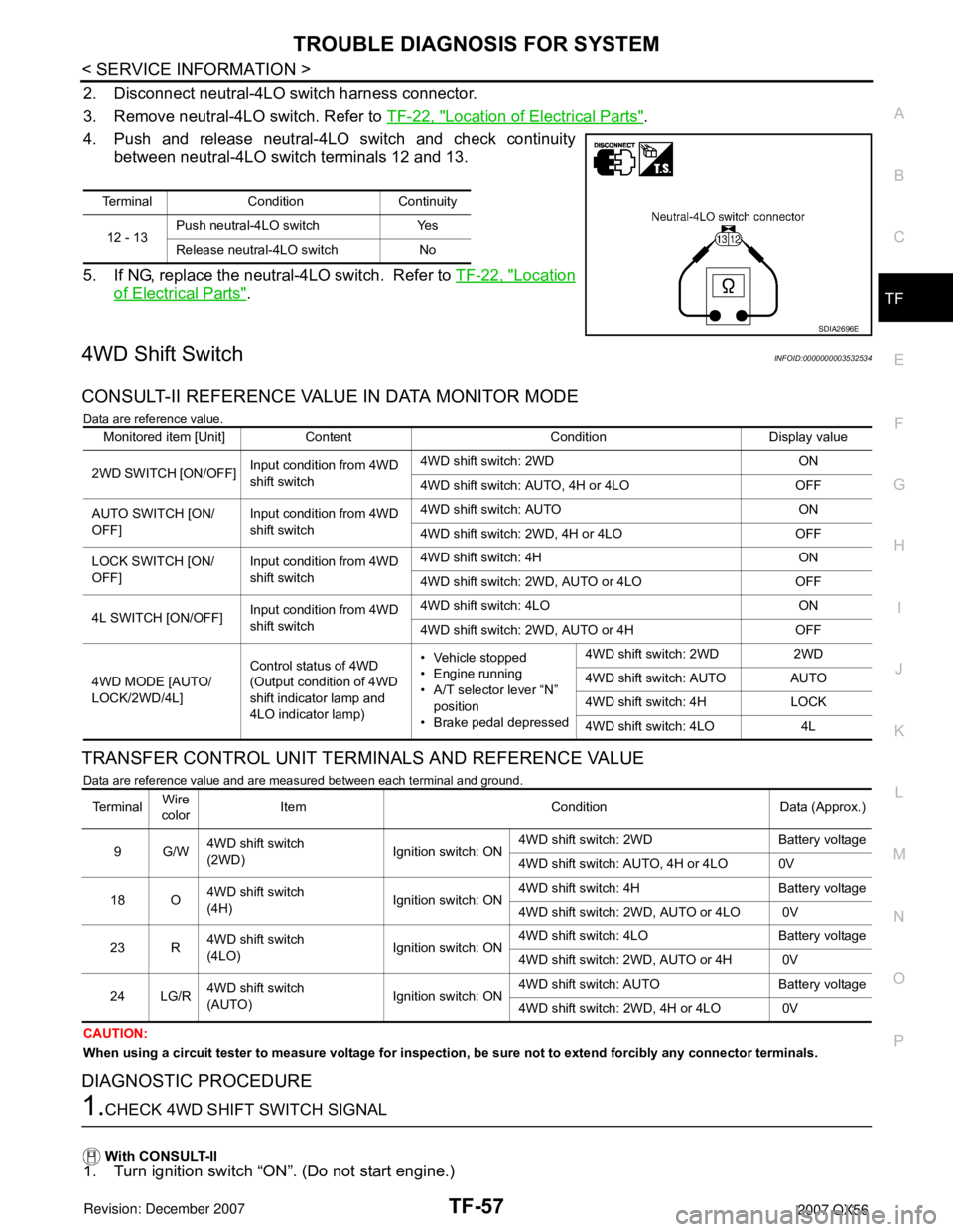
2. Disconnect neutral-4LO switch harness connector.
3. Remove neutral-4LO switch. Refer to TF-22, "
Location of Electrical Parts".
4. Push and release neutral-4LO switch and check continuity
between neutral-4LO switch terminals 12 and 13.
5. If NG, replace the neutral-4LO switch. Refer to TF-22, "
Location
of Electrical Parts".
4WD Shift SwitchINFOID:0000000003532534
CONSULT-II REFERENCE VALUE IN DATA MONITOR MODE
Data are reference value.
TRANSFER CONTROL UNIT TERMINALS AND REFERENCE VALUE
Data are reference value and are measured between each terminal and ground.
CAUTION:
When using a circuit tester to measure voltage for inspection, be sure not to extend forcibly any connector terminals.
DIAGNOSTIC PROCEDURE
1.CHECK 4WD SHIFT SWITCH SIGNAL
With CONSULT-II
1. Turn ignition switch “ON”. (Do not start engine.)
Terminal Condition Continuity
12 - 13Push neutral-4LO switch Yes
Release neutral-4LO switch No
SDIA2696E
Monitored item [Unit] Content Condition Display value
2WD SWITCH [ON/OFF]Input condition from 4WD
shift switch4WD shift switch: 2WD ON
4WD shift switch: AUTO, 4H or 4LO OFF
AUTO SWITCH [ON/
OFF]Input condition from 4WD
shift switch4WD shift switch: AUTO ON
4WD shift switch: 2WD, 4H or 4LO OFF
LOCK SWITCH [ON/
OFF]Input condition from 4WD
shift switch4WD shift switch: 4H ON
4WD shift switch: 2WD, AUTO or 4LO OFF
4L SWITCH [ON/OFF]Input condition from 4WD
shift switch4WD shift switch: 4LO ON
4WD shift switch: 2WD, AUTO or 4H OFF
4WD MODE [AUTO/
LOCK/2WD/4L]Control status of 4WD
(Output condition of 4WD
shift indicator lamp and
4LO indicator lamp)• Vehicle stopped
• Engine running
• A/T selector lever “N”
position
• Brake pedal depressed4WD shift switch: 2WD 2WD
4WD shift switch: AUTO AUTO
4WD shift switch: 4H LOCK
4WD shift switch: 4LO 4L
Te r m i n a lWire
colorItem Condition Data (Approx.)
9G/W4WD shift switch
(2WD)Ignition switch: ON4WD shift switch: 2WD Battery voltage
4WD shift switch: AUTO, 4H or 4LO 0V
18 O4WD shift switch
(4H)Ignition switch: ON4WD shift switch: 4H Battery voltage
4WD shift switch: 2WD, AUTO or 4LO 0V
23 R4WD shift switch
(4LO)Ignition switch: ON4WD shift switch: 4LO Battery voltage
4WD shift switch: 2WD, AUTO or 4H 0V
24 LG/R4WD shift switch
(AUTO)Ignition switch: ON4WD shift switch: AUTO Battery voltage
4WD shift switch: 2WD, 4H or 4LO 0V