2007 INFINITI QX56 stop start
[x] Cancel search: stop startPage 2302 of 3061
TRAILER TOW
LT-95
< SERVICE INFORMATION >
C
D
E
F
G
H
I
J
L
MA
B
LT
N
O
P
• to trailer tow relay 1 terminal 3,
• through 20A fuse (No. 53, located in the IPDM E/R)
• to CPU (central processing unit) of the IPDM E/R,
• through 30A fusible link (letter j , located in the fuse and fusible link box)
• to trailer tow relay 2 terminals 3 and 6, and
• through 40A fusible link (letter k , located in the fuse and fusible link box)
• to electric brake (pre-wiring) terminal 5.
With the ignition switch in the ON or START position, power is supplied
• to ignition relay, located in the IPDM E/R,
• through 10A fuse (No. 59, located in the fuse and relay box)
• to BCM terminal 38, and
• through 10A fuse (No. 51, located in the IPDM E/R)
• to trailer tow relay 2 terminal 1.
Ground is supplied
• to BCM terminal 67
• to electric brake (pre-wiring) terminal 1,
• through grounds M57, M61 and M79,
• to IPDM E/R terminals 38 and 59
• to trailer tow relay 1 terminal 2
• to trailer tow relay 2 terminal 2, and
• to trailer connector terminal 2
• to trailer turn relay LH and RH terminal 2
• through grounds E9, E15 and E24.
TRAILER TAIL LAMP OPERATION
The trailer tail lamps are controlled by the trailer tow relay 1.
With the lighting switch in the parking and tail lamp ON (1ST) position, AUTO position (and the auto light sys-
tem is activated) or headlamp ON (2ND) position, power is supplied
• through the tail lamp relay, located in the IPDM E/R
• through 10A fuse (No. 36, located in the IPDM E/R)
• through IPDM E/R terminal 49
• to trailer tow relay 1 terminal 1.
When energized, trailer tow relay 1 supplies tail lamp power to trailer connector terminal 6.
TRAILER TURN SIGNAL AND HAZARD LAMP OPERATION
The trailer turn signal and hazard lamps are controlled by the BCM through trailer turn relays (LH and RH). If
either turn signal or the hazard lamps are turned on, the BCM supplies voltage to the trailer turn relays (LH
and RH) to make them cycle on and off.
Trailer turn relay LH output is supplied
• through BCM terminal 52
• to trailer turn relay LH terminal 1.
Trailer turn relay RH output is supplied
• through BCM terminal 51
• to trailer turn relay RH terminal 1.
Left turn signal and hazard lamp output is supplied
• through trailer turn relay LH terminal 3
• to trailer connector terminal 1.
Right turn signal and hazard lamp output is supplied
• through trailer turn relay RH terminal 3
• to trailer connector terminal 4.
TRAILER STOP LAMP OPERATION
The trailer stop lamps are controlled by the electric brake. The electric brake receives stop lamp switch signal
when the brake pedal is pressed.
When the brake pedal is pressed, power is supplied
• through electric brake (pre-wiring) terminal 3
• to trailer connector terminal 3.
TRAILER POWER SUPPLY OPERATION
The trailer power supply is controlled by the trailer tow relay 2.
When the ignition switch is in the ON or START position, power is supplied
• through 10A fuse (No. 51, located in the IPDM E/R)
Page 2354 of 3061
ENGINE OIL
LU-9
< SERVICE INFORMATION >
C
D
E
F
G
H
I
J
K
L
MA
LU
N
P O
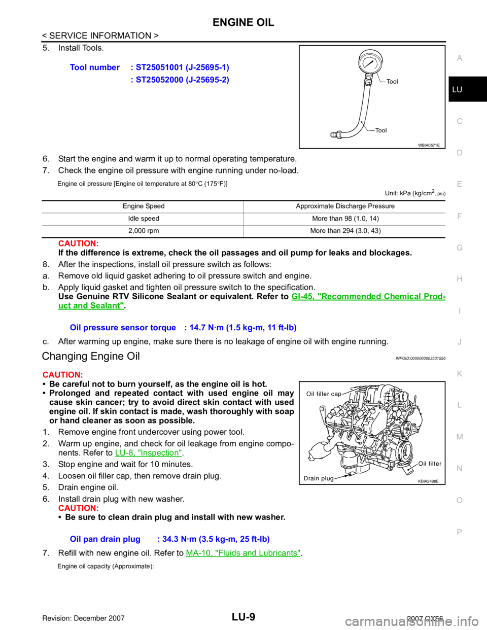
5. Install Tools.
6. Start the engine and warm it up to normal operating temperature.
7. Check the engine oil pressure with engine running under no-load.
Engine oil pressure [Engine oil temperature at 80°C (175°F)]
Unit: kPa (kg/cm2
, psi)
CAUTION:
If the difference is extreme, check the oil passages and oil pump for leaks and blockages.
8. After the inspections, install oil pressure switch as follows:
a. Remove old liquid gasket adhering to oil pressure switch and engine.
b. Apply liquid gasket and tighten oil pressure switch to the specification.
Use Genuine RTV Silicone Sealant or equivalent. Refer to GI-45, "
Recommended Chemical Prod-
uct and Sealant".
c. After warming up engine, make sure there is no leakage of engine oil with engine running.
Changing Engine OilINFOID:0000000003531556
CAUTION:
• Be careful not to burn yourself, as the engine oil is hot.
• Prolonged and repeated contact with used engine oil may
cause skin cancer; try to avoid direct skin contact with used
engine oil. If skin contact is made, wash thoroughly with soap
or hand cleaner as soon as possible.
1. Remove engine front undercover using power tool.
2. Warm up engine, and check for oil leakage from engine compo-
nents. Refer to LU-8, "
Inspection".
3. Stop engine and wait for 10 minutes.
4. Loosen oil filler cap, then remove drain plug.
5. Drain engine oil.
6. Install drain plug with new washer.
CAUTION:
• Be sure to clean drain plug and install with new washer.
7. Refill with new engine oil. Refer to MA-10, "
Fluids and Lubricants".
Engine oil capacity (Approximate):
Tool number : ST25051001 (J-25695-1)
: ST25052000 (J-25695-2)
WBIA0571E
Engine Speed Approximate Discharge Pressure
Idle speed More than 98 (1.0, 14)
2,000 rpm More than 294 (3.0, 43)
Oil pressure sensor torque : 14.7 N·m (1.5 kg-m, 11 ft-lb)
Oil pan drain plug : 34.3 N·m (3.5 kg-m, 25 ft-lb)
KBIA2498E
Page 2356 of 3061

OIL FILTER
LU-11
< SERVICE INFORMATION >
C
D
E
F
G
H
I
J
K
L
MA
LU
N
P O
OIL FILTER
Removal and InstallationINFOID:0000000003531557
REMOVAL
1. Remove the engine front undercover using power tool.
2. Remove the oil filter using Tool.
WARNING:
• The oil filter is provided with a relief valve.
Use Genuine NISSAN oil filter or equivalent.
• When removing, prepare a shop cloth to absorb any
engine oil leakage or spillage.
• Do not allow engine oil to adhere to the drive belts.
• Completely wipe off any engine oil that adheres to the
engine and the vehicle.
CAUTION:
• Be careful not to get burned when the engine and engine oil are hot.
INSTALLATION
1. Remove foreign materials adhering to the oil filter installation surface.
2. Apply engine oil to the oil seal circumference of the new oil filter.
3. Screw the oil filter manually until it touches the installation sur-
face, then tighten it by 2/3 turn. Or tighten to specification.
4. Inspect the engine for oil leakage. Refer to EM-74, "
Removal
and Installation".
5. Install the engine front undercover using power tool.
INSPECTION AFTER INSTALLATION
1. Check the engine oil level. Refer to LU-8, "Inspection".
2. Start the engine and check for engine oil leakage.
3. Stop the engine and wait for 10 minutes.
4. Check the engine oil level and add engine oil as required.Tool number : KV10115801 (J-38956)
WBIA0388E
SMA010
Oil filter : 17.7 N·m (1.8 kg-m, 13 ft-lb)
SMA229B
Page 2358 of 3061
OIL COOLER
LU-13
< SERVICE INFORMATION >
C
D
E
F
G
H
I
J
K
L
MA
LU
N
P O
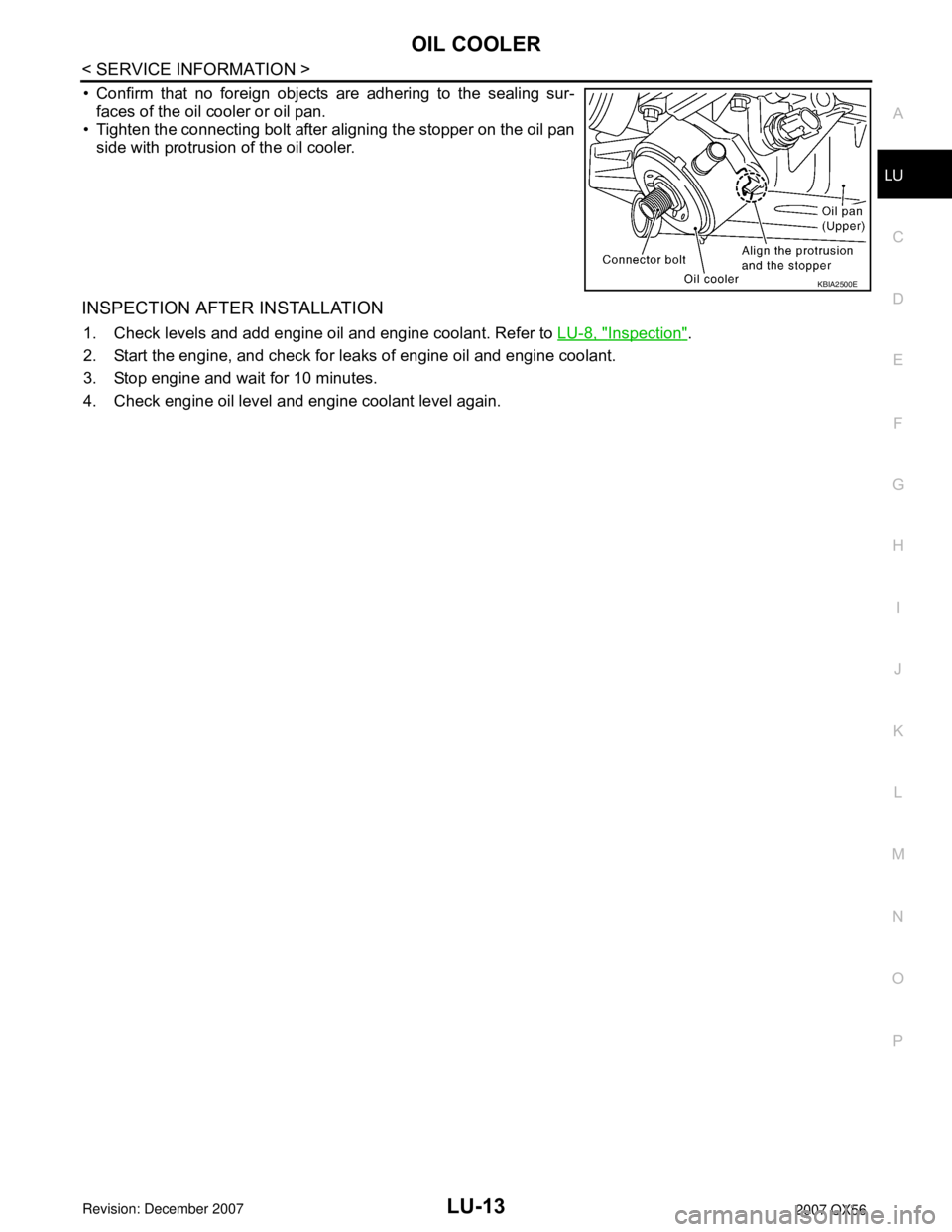
• Confirm that no foreign objects are adhering to the sealing sur-
faces of the oil cooler or oil pan.
• Tighten the connecting bolt after aligning the stopper on the oil pan
side with protrusion of the oil cooler.
INSPECTION AFTER INSTALLATION
1. Check levels and add engine oil and engine coolant. Refer to LU-8, "Inspection".
2. Start the engine, and check for leaks of engine oil and engine coolant.
3. Stop engine and wait for 10 minutes.
4. Check engine oil level and engine coolant level again.
KBIA2500E
Page 2359 of 3061
LU-14
< SERVICE INFORMATION >
OIL PUMP
OIL PUMP
Removal and InstallationINFOID:0000000003531559
REMOVAL
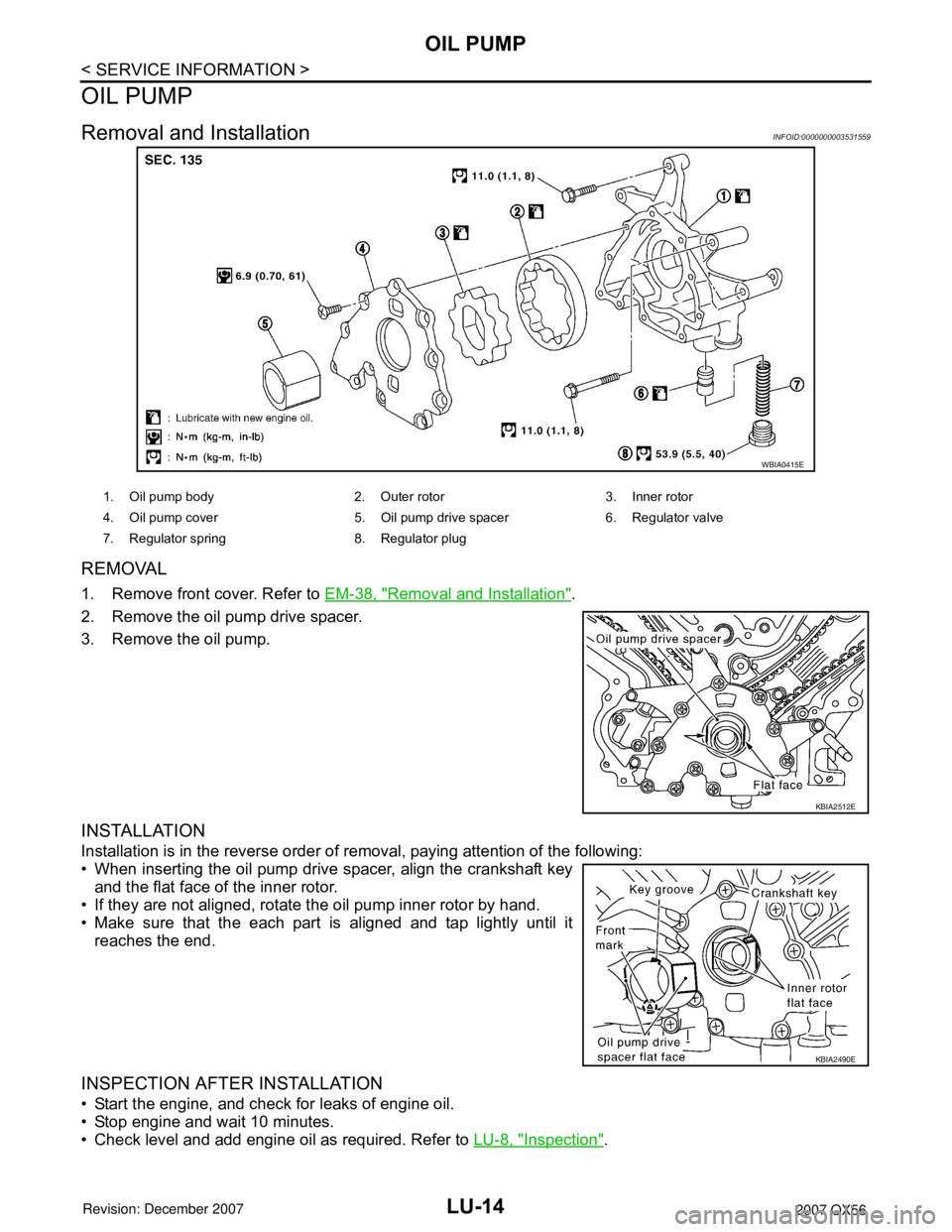
1. Remove front cover. Refer to EM-38, "Removal and Installation".
2. Remove the oil pump drive spacer.
3. Remove the oil pump.
INSTALLATION
Installation is in the reverse order of removal, paying attention of the following:
• When inserting the oil pump drive spacer, align the crankshaft key
and the flat face of the inner rotor.
• If they are not aligned, rotate the oil pump inner rotor by hand.
• Make sure that the each part is aligned and tap lightly until it
reaches the end.
INSPECTION AFTER INSTALLATION
• Start the engine, and check for leaks of engine oil.
• Stop engine and wait 10 minutes.
• Check level and add engine oil as required. Refer to LU-8, "
Inspection".
WBIA0415E
1. Oil pump body 2. Outer rotor 3. Inner rotor
4. Oil pump cover 5. Oil pump drive spacer 6. Regulator valve
7. Regulator spring 8. Regulator plug
KBIA2512E
KBIA2490E
Page 2379 of 3061
ENGINE MAINTENANCE
MA-17
< SERVICE INFORMATION >
C
D
E
F
G
H
I
J
K
MA
B
MA
N
O
P
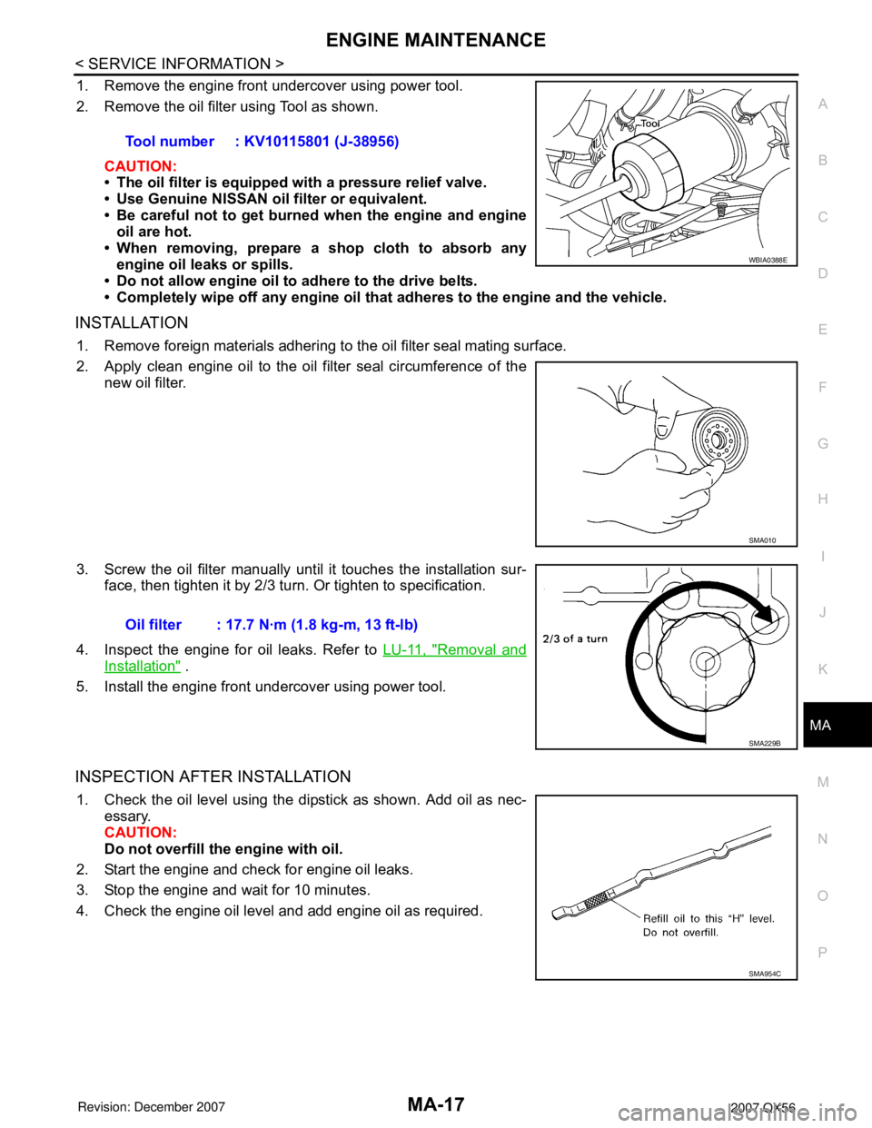
1. Remove the engine front undercover using power tool.
2. Remove the oil filter using Tool as shown.
CAUTION:
• The oil filter is equipped with a pressure relief valve.
• Use Genuine NISSAN oil filter or equivalent.
• Be careful not to get burned when the engine and engine
oil are hot.
• When removing, prepare a shop cloth to absorb any
engine oil leaks or spills.
• Do not allow engine oil to adhere to the drive belts.
• Completely wipe off any engine oil that adheres to the engine and the vehicle.
INSTALLATION
1. Remove foreign materials adhering to the oil filter seal mating surface.
2. Apply clean engine oil to the oil filter seal circumference of the
new oil filter.
3. Screw the oil filter manually until it touches the installation sur-
face, then tighten it by 2/3 turn. Or tighten to specification.
4. Inspect the engine for oil leaks. Refer to LU-11, "
Removal and
Installation" .
5. Install the engine front undercover using power tool.
INSPECTION AFTER INSTALLATION
1. Check the oil level using the dipstick as shown. Add oil as nec-
essary.
CAUTION:
Do not overfill the engine with oil.
2. Start the engine and check for engine oil leaks.
3. Stop the engine and wait for 10 minutes.
4. Check the engine oil level and add engine oil as required.Tool number : KV10115801 (J-38956)
WBIA0388E
SMA010
Oil filter : 17.7 N·m (1.8 kg-m, 13 ft-lb)
SMA229B
SMA954C
Page 2419 of 3061
IPDM E/R (INTELLIGENT POWER DISTRIBUTION MODULE ENGINE ROOM)
PG-17
< SERVICE INFORMATION >
C
D
E
F
G
H
I
J
L
MA
B
PG
N
O
P
IPDM E/R (INTELLIGENT POWER DISTRIBUTION MODULE ENGINE
ROOM)
System DescriptionINFOID:0000000003533835
• IPDM E/R (Intelligent Power Distribution Module Engine Room) integrates the relay box and fuse block
which were originally placed in engine compartment. It controls integrated relays via IPDM E/R control cir-
cuits.
• IPDM E/R-integrated control circuits perform ON-OFF operation of relays, CAN communication control, etc.
• It controls operation of each electrical component via ECM, BCM and CAN communication lines.
CAUTION:
None of the IPDM E/R integrated relays can be removed.
SYSTEMS CONTROLLED BY IPDM E/R
1. Lamp control
Using CAN communication lines, it receives signals from the BCM and controls the following lamps:
• Headlamps (Hi, Lo)
• Parking lamps
• Tail and license lamps
• Front fog lamps
2. Wiper control
Using CAN communication lines, it receives signals from the BCM and controls the front wipers.
3. Rear window defogger relay control
Using CAN communication lines, it receives signals from the BCM and controls the rear window defogger
relay.
4. A/C compressor control
Using CAN communication lines, it receives signals from the ECM and controls the A/C compressor
(magnetic clutch).
5. Starter control
Using CAN communication lines, it receives signals from the BCM and controls the starter relay.
6. Cooling fan control
Using CAN communication lines, it receives signals from the ECM and controls the cooling fan relays.
7. Horn control
Using CAN communication lines, it receives signals from the BCM and controls the horn relay.
CAN COMMUNICATION LINE CONTROL
With CAN communication, by connecting each control unit using two communication lines (CAN L-line, CAN
H-line), it is possible to transmit a maximum amount of information with minimum wiring. Each control unit can
transmit and receive data, and reads necessary information only.
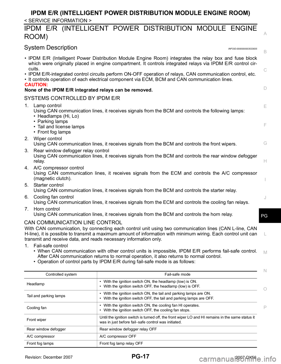
1. Fail-safe control
• When CAN communication with other control units is impossible, IPDM E/R performs fail-safe control.
After CAN communication returns to normal operation, it also returns to normal control.
• Operation of control parts by IPDM E/R during fail-safe mode is as follows:
Controlled system Fail-safe mode
Headlamp• With the ignition switch ON, the headlamp (low) is ON.
• With the ignition switch OFF, the headlamp (low) is OFF.
Tail and parking lamps• With the ignition switch ON, the tail and parking lamps are ON.
• With the ignition switch OFF, the tail and parking lamps are OFF.
Cooling fan• With the ignition switch ON, the cooling fan HI operates.
• With the ignition switch OFF, the cooling fan stops.
Front wiperUntil the ignition switch is turned off, the front wiper LO and HI remains in the same status it
was in just before fail−safe control was initiated.
Rear window defogger Rear window defogger relay OFF
A/C compressor A/C compressor OFF
Front fog lamps Front fog lamp relay OFF
Page 2420 of 3061
PG-18
< SERVICE INFORMATION >
IPDM E/R (INTELLIGENT POWER DISTRIBUTION MODULE ENGINE ROOM)
IPDM E/R STATUS CONTROL
In order to save power, IPDM E/R switches status automatically based on each operating condition.
1. CAN communication status
• CAN communication is normally performed with other control units.
• Individual unit control by IPDM E/R is normally performed.
• When sleep request signal is received from BCM, mode is switched to sleep waiting status.
2. Sleep waiting status
• Process to stop CAN communication is activated.
• All systems controlled by IPDM E/R are stopped. When 1 second has elapsed after CAN communica-
tion with other control units is stopped, mode switches to sleep status.
3. Sleep status
• IPDM E/R operates in low current-consumption mode.
• CAN communication is stopped.
• When a change in CAN communication signal is detected, mode switches to CAN communication sta-
tus.
• When a change in ignition switch signal is detected, mode switches to CAN communication status.
CAN Communication System DescriptionINFOID:0000000003533836
Refer to LAN-4.
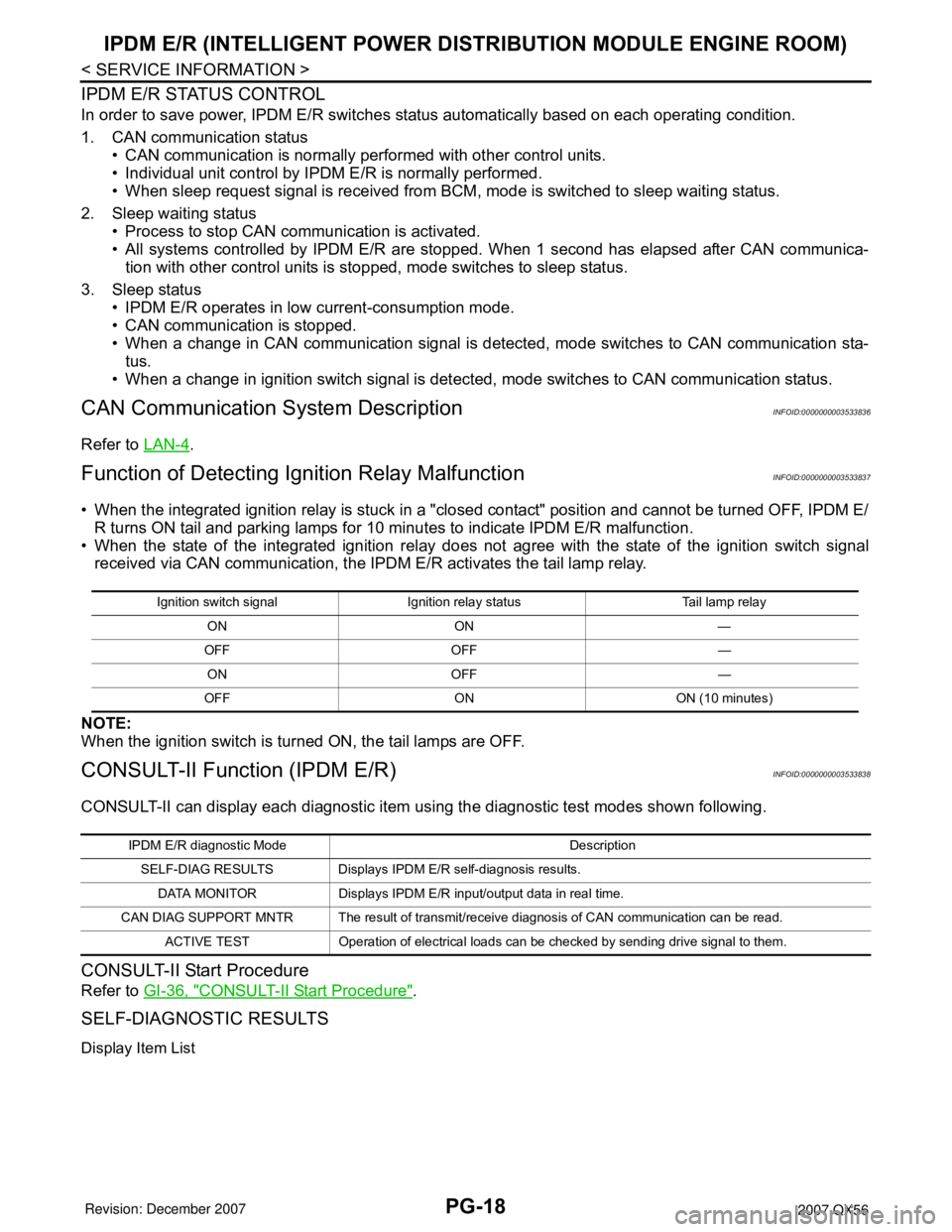
Function of Detecting Ignition Relay MalfunctionINFOID:0000000003533837
• When the integrated ignition relay is stuck in a "closed contact" position and cannot be turned OFF, IPDM E/
R turns ON tail and parking lamps for 10 minutes to indicate IPDM E/R malfunction.
• When the state of the integrated ignition relay does not agree with the state of the ignition switch signal
received via CAN communication, the IPDM E/R activates the tail lamp relay.
NOTE:
When the ignition switch is turned ON, the tail lamps are OFF.
CONSULT-II Function (IPDM E/R)INFOID:0000000003533838
CONSULT-II can display each diagnostic item using the diagnostic test modes shown following.
CONSULT-II Start Procedure
Refer to GI-36, "CONSULT-II Start Procedure".
SELF-DIAGNOSTIC RESULTS
Display Item List
Ignition switch signal Ignition relay status Tail lamp relay
ON ON —
OFF OFF —
ON OFF —
OFF ON ON (10 minutes)
IPDM E/R diagnostic Mode Description
SELF-DIAG RESULTS Displays IPDM E/R self-diagnosis results.
DATA MONITOR Displays IPDM E/R input/output data in real time.
CAN DIAG SUPPORT MNTR The result of transmit/receive diagnosis of CAN communication can be read.
ACTIVE TEST Operation of electrical loads can be checked by sending drive signal to them.