2007 INFINITI QX56 stop start
[x] Cancel search: stop startPage 2907 of 3061
TROUBLE DIAGNOSIS FOR SYSTEM
TF-85
< SERVICE INFORMATION >
C
E
F
G
H
I
J
K
L
MA
B
TF
N
O
P
CAUTION:
When using a circuit tester to measure voltage for inspection, be sure not to extend forcibly any connector terminals.
DIAGNOSTIC PROCEDURE
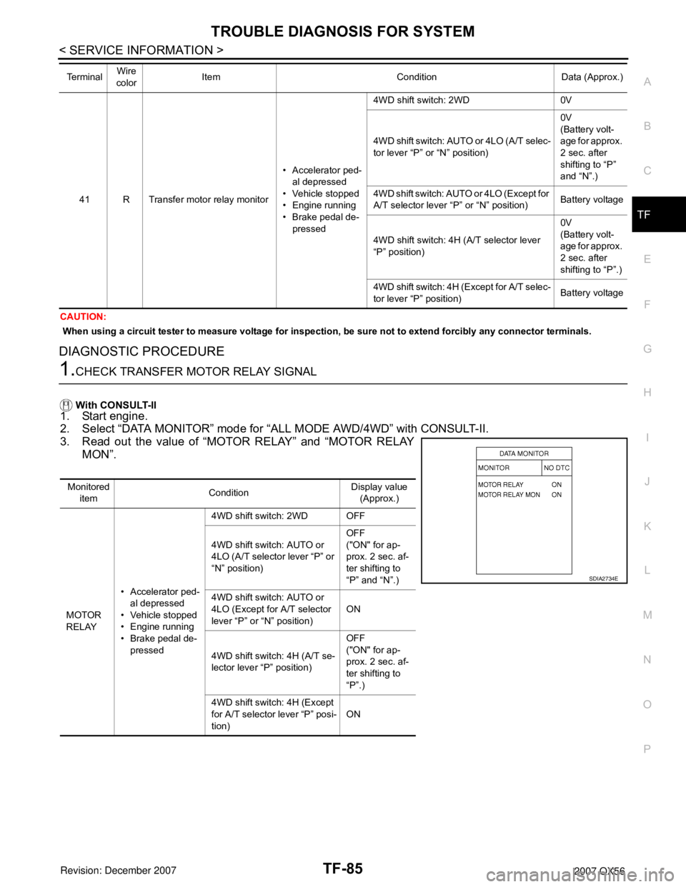
1.CHECK TRANSFER MOTOR RELAY SIGNAL
With CONSULT-II
1. Start engine.
2. Select “DATA MONITOR” mode for “ALL MODE AWD/4WD” with CONSULT-II.
3. Read out the value of “MOTOR RELAY” and “MOTOR RELAY
MON”.
41 R Transfer motor relay monitor• Accelerator ped-
al depressed
• Vehicle stopped
• Engine running
• Brake pedal de-
pressed4WD shift switch: 2WD 0V
4WD shift switch: AUTO or 4LO (A/T selec-
tor lever “P” or “N” position)0V
(Battery volt-
age for approx.
2 sec. after
shifting to “P”
and “N”.)
4WD shift switch: AUTO or 4LO (Except for
A/T selector lever “P” or “N” position)Battery voltage
4WD shift switch: 4H (A/T selector lever
“P” position)0V
(Battery volt-
age for approx.
2 sec. after
shifting to “P”.)
4WD shift switch: 4H (Except for A/T selec-
tor lever “P” position)Battery voltage Te r m i n a lWire
colorItem Condition Data (Approx.)
Monitored
itemConditionDisplay value
(Approx.)
MOTOR
RELAY• Accelerator ped-
al depressed
• Vehicle stopped
• Engine running
• Brake pedal de-
pressed4WD shift switch: 2WD OFF
4WD shift switch: AUTO or
4LO (A/T selector lever “P” or
“N” position)OFF
("ON" for ap-
prox. 2 sec. af-
ter shifting to
“P” and “N”.)
4WD shift switch: AUTO or
4LO (Except for A/T selector
lever “P” or “N” position)ON
4WD shift switch: 4H (A/T se-
lector lever “P” position)OFF
("ON" for ap-
prox. 2 sec. af-
ter shifting to
“P”.)
4WD shift switch: 4H (Except
for A/T selector lever “P” posi-
tion)ON
SDIA2734E
Page 2908 of 3061
TF-86
< SERVICE INFORMATION >
TROUBLE DIAGNOSIS FOR SYSTEM
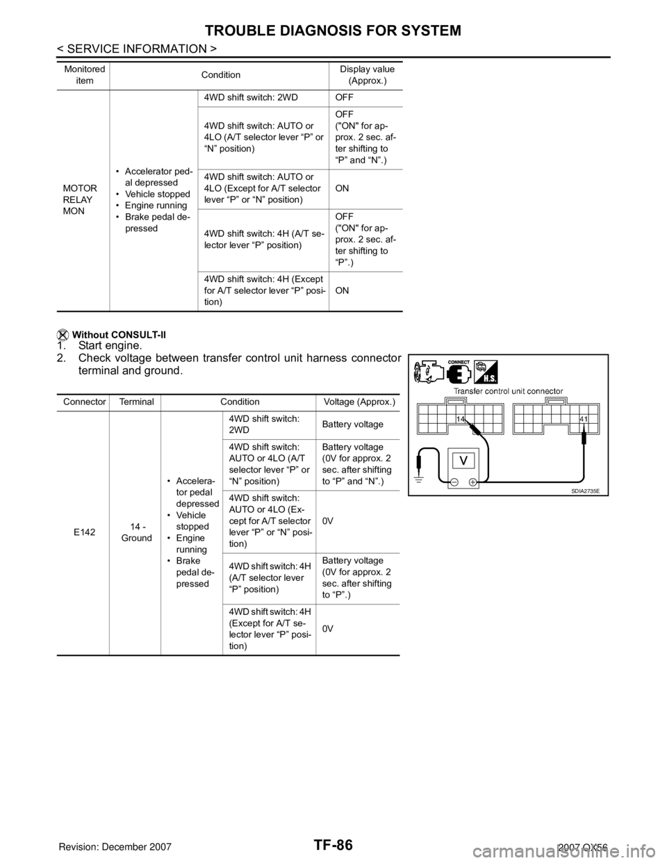
Without CONSULT-II
1. Start engine.
2. Check voltage between transfer control unit harness connector
terminal and ground.
MOTOR
RELAY
MON• Accelerator ped-
al depressed
• Vehicle stopped
• Engine running
• Brake pedal de-
pressed4WD shift switch: 2WD OFF
4WD shift switch: AUTO or
4LO (A/T selector lever “P” or
“N” position)OFF
("ON" for ap-
prox. 2 sec. af-
ter shifting to
“P” and “N”.)
4WD shift switch: AUTO or
4LO (Except for A/T selector
lever “P” or “N” position)ON
4WD shift switch: 4H (A/T se-
lector lever “P” position)OFF
("ON" for ap-
prox. 2 sec. af-
ter shifting to
“P”.)
4WD shift switch: 4H (Except
for A/T selector lever “P” posi-
tion)ON Monitored
itemConditionDisplay value
(Approx.)
Connector Terminal Condition Voltage (Approx.)
E142 14 -
Ground• Accelera-
tor pedal
depressed
• Vehicle
stopped
•Engine
running
•Brake
pedal de-
pressed4WD shift switch:
2WDBattery voltage
4WD shift switch:
AUTO or 4LO (A/T
selector lever “P” or
“N” position)Battery voltage
(0V for approx. 2
sec. after shifting
to “P” and “N”.)
4WD shift switch:
AUTO or 4LO (Ex-
cept for A/T selector
lever “P” or “N” posi-
tion)0V
4WD shift switch: 4H
(A/T selector lever
“P” position)Battery voltage
(0V for approx. 2
sec. after shifting
to “P”.)
4WD shift switch: 4H
(Except for A/T se-
lector lever “P” posi-
tion)0V
SDIA2735E
Page 2909 of 3061
TROUBLE DIAGNOSIS FOR SYSTEM
TF-87
< SERVICE INFORMATION >
C
E
F
G
H
I
J
K
L
MA
B
TF
N
O
P
OK or NG
OK >> GO TO 7.
NG >> GO TO 2.
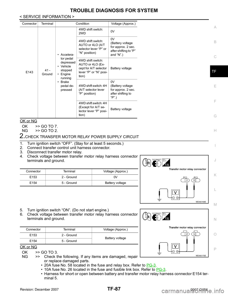
2.CHECK TRANSFER MOTOR RELAY POWER SUPPLY CIRCUIT
1. Turn ignition switch “OFF”. (Stay for at least 5 seconds.)
2. Connect transfer control unit harness connector.
3. Disconnect transfer motor relay.
4. Check voltage between transfer motor relay harness connector
terminals and ground.
5. Turn ignition switch “ON”. (Do not start engine.)
6. Check voltage between transfer motor relay harness connector
terminals and ground.
OK or NG
OK >> GO TO 3.
NG >> Check the following. If any items are damaged, repair
or replace damaged parts.
• 20A fuse No. 58 located in the fuse and relay box. Refer to PG-3
.
• 10A fuse No. 26 located in the fuse and fusible link box. Refer to PG-3
.
• Harness for short or open between battery and transfer motor relay harness connector E154 ter-
minal 5.
E143 41 -
Ground• Accelera-
tor pedal
depressed
• Vehicle
stopped
•Engine
running
•Brake
pedal de-
pressed4WD shift switch:
2WD0V
4WD shift switch:
AUTO or 4LO (A/T
selector lever “P” or
“N” position)0V
(Battery voltage
for approx. 2 sec.
after shifting to “P”
and “N”.)
4WD shift switch:
AUTO or 4LO (Ex-
cept for A/T selector
lever “P” or “N” posi-
tion)Battery voltage
4WD shift switch: 4H
(A/T selector lever
“P” position)0V
(Battery voltage
for approx. 2 sec.
after shifting to
“P”.)
4WD shift switch: 4H
(Except for A/T se-
lector lever “P” posi-
tion)Battery voltage Connector Terminal Condition Voltage (Approx.)
Connector Terminal Voltage (Approx.)
E153 2 - Ground 0V
E154 5 - Ground Battery voltage
WDIA0169E
Connector Terminal Voltage (Approx.)
E153 2 - Ground
Battery voltage
E154 5 - Ground
WDIA0170E
Page 2914 of 3061
TF-92
< SERVICE INFORMATION >
TROUBLE DIAGNOSIS FOR SYSTEM
Perform the self-diagnosis, after driving a vehicle for a while.
OK or NG
OK >> Inspection End.
NG >> Replace transfer control unit. Refer to TF-115, "
Removal and Installation".
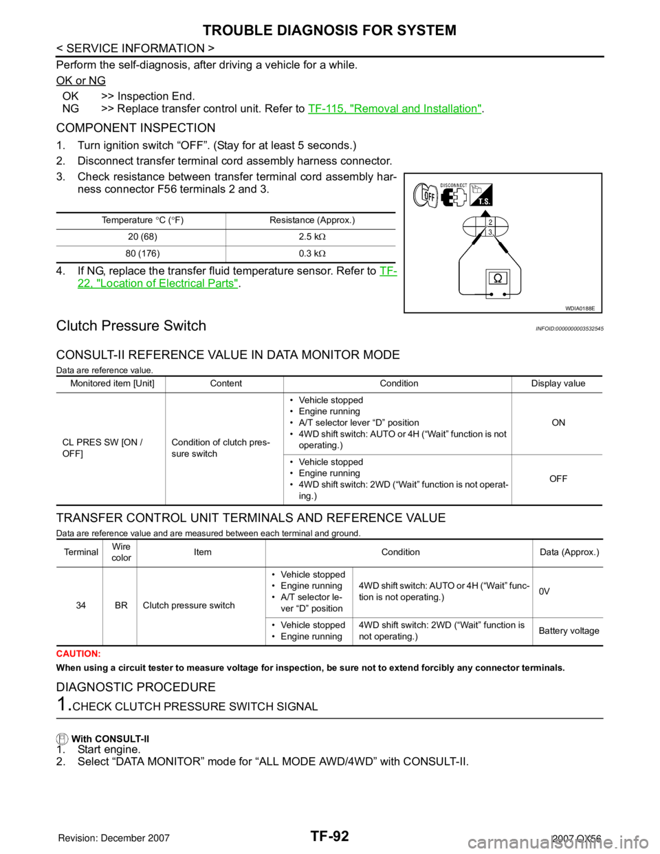
COMPONENT INSPECTION
1. Turn ignition switch “OFF”. (Stay for at least 5 seconds.)
2. Disconnect transfer terminal cord assembly harness connector.
3. Check resistance between transfer terminal cord assembly har-
ness connector F56 terminals 2 and 3.
4. If NG, replace the transfer fluid temperature sensor. Refer to TF-
22, "Location of Electrical Parts".
Clutch Pressure SwitchINFOID:0000000003532545
CONSULT-II REFERENCE VALUE IN DATA MONITOR MODE
Data are reference value.
TRANSFER CONTROL UNIT TERMINALS AND REFERENCE VALUE
Data are reference value and are measured between each terminal and ground.
CAUTION:
When using a circuit tester to measure voltage for inspection, be sure not to extend forcibly any connector terminals.
DIAGNOSTIC PROCEDURE
1.CHECK CLUTCH PRESSURE SWITCH SIGNAL
With CONSULT-II
1. Start engine.
2. Select “DATA MONITOR” mode for “ALL MODE AWD/4WD” with CONSULT-II.
Temperature °C (°F) Resistance (Approx.)
20 (68) 2.5 kΩ
80 (176) 0.3 kΩ
WDIA0188E
Monitored item [Unit] Content Condition Display value
CL PRES SW [ON /
OFF]Condition of clutch pres-
sure switch• Vehicle stopped
• Engine running
• A/T selector lever “D” position
• 4WD shift switch: AUTO or 4H (“Wait” function is not
operating.)ON
• Vehicle stopped
• Engine running
• 4WD shift switch: 2WD (“Wait” function is not operat-
ing.)OFF
Te r m i n a lWire
colorItem Condition Data (Approx.)
34 BR Clutch pressure switch• Vehicle stopped
• Engine running
• A/T selector le-
ver “D” position4WD shift switch: AUTO or 4H (“Wait” func-
tion is not operating.)0V
• Vehicle stopped
• Engine running4WD shift switch: 2WD (“Wait” function is
not operating.)Battery voltage
Page 2921 of 3061
TROUBLE DIAGNOSIS FOR SYSTEM
TF-99
< SERVICE INFORMATION >
C
E
F
G
H
I
J
K
L
MA
B
TF
N
O
P
CAN Communication LineINFOID:0000000003532551
DIAGNOSTIC PROCEDURE
1.CHECK CAN COMMUNICATION CIRCUIT
With CONSULT-II
1. Turn ignition switch “ON” and start engine.
2. Select “SELF-DIAG RESULTS” mode for “ALL MODE AWD/4WD” within CONSULT-II.
3. Perform the self-diagnosis.
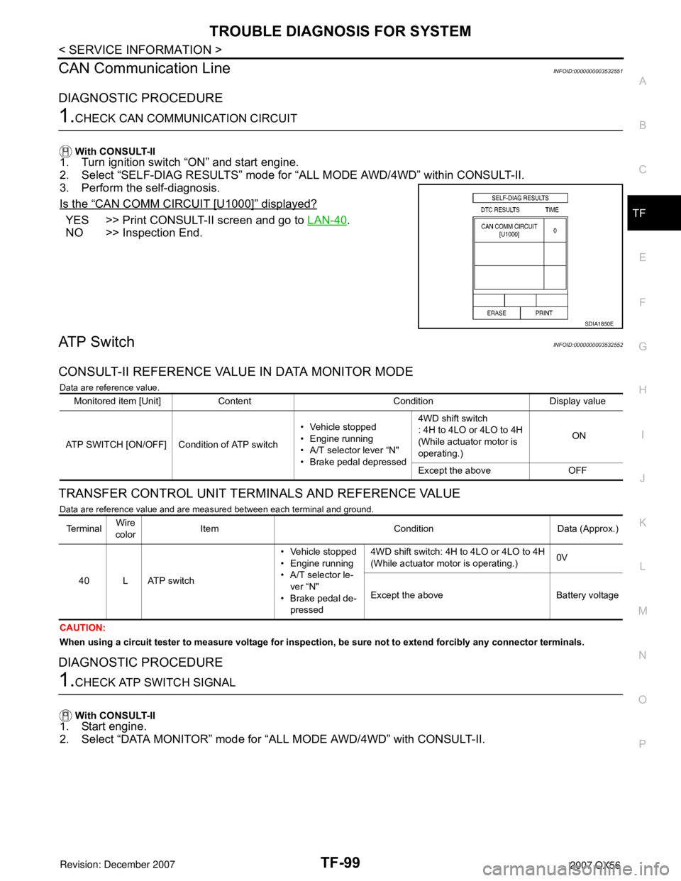
Is the
“CAN COMM CIRCUIT [U1000]” displayed?
YES >> Print CONSULT-II screen and go to LAN-40.
NO >> Inspection End.
ATP SwitchINFOID:0000000003532552
CONSULT-II REFERENCE VALUE IN DATA MONITOR MODE
Data are reference value.
TRANSFER CONTROL UNIT TERMINALS AND REFERENCE VALUE
Data are reference value and are measured between each terminal and ground.
CAUTION:
When using a circuit tester to measure voltage for inspection, be sure not to extend forcibly any connector terminals.
DIAGNOSTIC PROCEDURE
1.CHECK ATP SWITCH SIGNAL
With CONSULT-II
1. Start engine.
2. Select “DATA MONITOR” mode for “ALL MODE AWD/4WD” with CONSULT-II.
SDIA1850E
Monitored item [Unit] Content Condition Display value
ATP SWITCH [ON/OFF] Condition of ATP switch• Vehicle stopped
• Engine running
• A/T selector lever “N"
• Brake pedal depressed4WD shift switch
: 4H to 4LO or 4LO to 4H
(While actuator motor is
operating.) ON
Except the above OFF
Te r m i n a lWire
colorItem Condition Data (Approx.)
40 L ATP switch• Vehicle stopped
• Engine running
• A/T selector le-
ver “N"
• Brake pedal de-
pressed4WD shift switch: 4H to 4LO or 4LO to 4H
(While actuator motor is operating.)0V
Except the above Battery voltage
Page 2922 of 3061
TF-100
< SERVICE INFORMATION >
TROUBLE DIAGNOSIS FOR SYSTEM
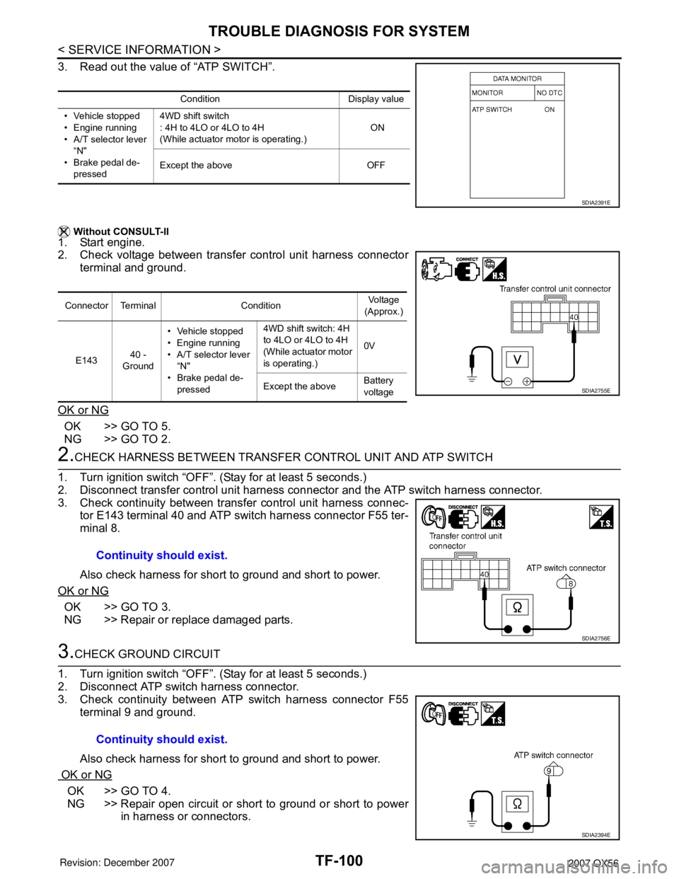
3. Read out the value of “ATP SWITCH”.
Without CONSULT-II
1. Start engine.
2. Check voltage between transfer control unit harness connector
terminal and ground.
OK or NG
OK >> GO TO 5.
NG >> GO TO 2.
2.CHECK HARNESS BETWEEN TRANSFER CONTROL UNIT AND ATP SWITCH
1. Turn ignition switch “OFF”. (Stay for at least 5 seconds.)
2. Disconnect transfer control unit harness connector and the ATP switch harness connector.
3. Check continuity between transfer control unit harness connec-
tor E143 terminal 40 and ATP switch harness connector F55 ter-
minal 8.
Also check harness for short to ground and short to power.
OK or NG
OK >> GO TO 3.
NG >> Repair or replace damaged parts.
3.CHECK GROUND CIRCUIT
1. Turn ignition switch “OFF”. (Stay for at least 5 seconds.)
2. Disconnect ATP switch harness connector.
3. Check continuity between ATP switch harness connector F55
terminal 9 and ground.
Also check harness for short to ground and short to power.
OK or NG
OK >> GO TO 4.
NG >> Repair open circuit or short to ground or short to power
in harness or connectors.
Condition Display value
• Vehicle stopped
• Engine running
• A/T selector lever
“N"
• Brake pedal de-
pressed4WD shift switch
: 4H to 4LO or 4LO to 4H
(While actuator motor is operating.) ON
Except the above OFF
SDIA2391E
Connector Terminal ConditionVoltage
(Approx.)
E14340 -
Ground• Vehicle stopped
• Engine running
• A/T selector lever
“N"
• Brake pedal de-
pressed4WD shift switch: 4H
to 4LO or 4LO to 4H
(While actuator motor
is operating.)0V
Except the aboveBattery
voltage
SDIA2755E
Continuity should exist.
SDIA2756E
Continuity should exist.
SDIA2394E
Page 2947 of 3061
TRANSFER MOTOR
TF-125
< SERVICE INFORMATION >
C
E
F
G
H
I
J
K
L
MA
B
TF
N
O
P
TRANSFER MOTOR
Removal and InstallationINFOID:0000000003532568
REMOVAL
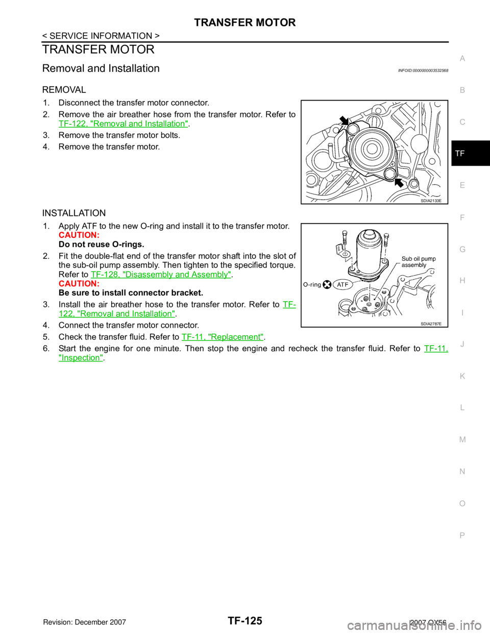
1. Disconnect the transfer motor connector.
2. Remove the air breather hose from the transfer motor. Refer to
TF-122, "
Removal and Installation".
3. Remove the transfer motor bolts.
4. Remove the transfer motor.
INSTALLATION
1. Apply ATF to the new O-ring and install it to the transfer motor.
CAUTION:
Do not reuse O-rings.
2. Fit the double-flat end of the transfer motor shaft into the slot of
the sub-oil pump assembly. Then tighten to the specified torque.
Refer to TF-128, "
Disassembly and Assembly".
CAUTION:
Be sure to install connector bracket.
3. Install the air breather hose to the transfer motor. Refer to TF-
122, "Removal and Installation".
4. Connect the transfer motor connector.
5. Check the transfer fluid. Refer to TF-11, "
Replacement".
6. Start the engine for one minute. Then stop the engine and recheck the transfer fluid. Refer to TF-11,
"Inspection".
SDIA2133E
SDIA2787E
Page 2949 of 3061
TRANSFER OIL FILTER
TF-127
< SERVICE INFORMATION >
C
E
F
G
H
I
J
K
L
MA
B
TF
N
O
P
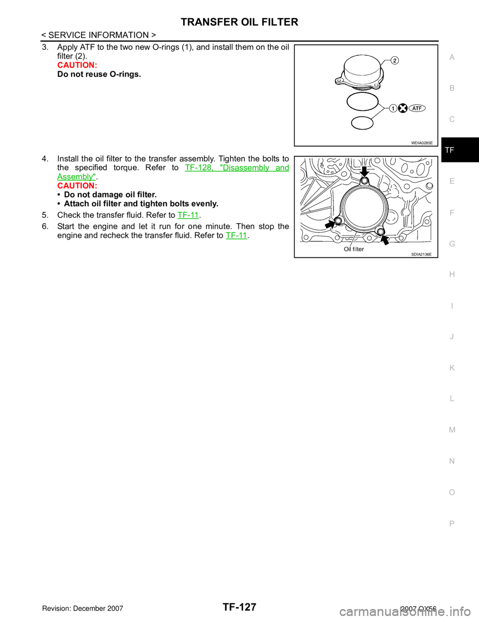
3. Apply ATF to the two new O-rings (1), and install them on the oil
filter (2).
CAUTION:
Do not reuse O-rings.
4. Install the oil filter to the transfer assembly. Tighten the bolts to
the specified torque. Refer to TF-128, "
Disassembly and
Assembly".
CAUTION:
• Do not damage oil filter.
• Attach oil filter and tighten bolts evenly.
5. Check the transfer fluid. Refer to TF-11
.
6. Start the engine and let it run for one minute. Then stop the
engine and recheck the transfer fluid. Refer to TF-11
.
WDIA0285E
SDIA2136E