2007 INFINITI QX56 stop start
[x] Cancel search: stop startPage 1935 of 3061
FL-4
< SERVICE INFORMATION >
FUEL SYSTEM
FUEL SYSTEM
Checking Fuel LineINFOID:0000000003532203
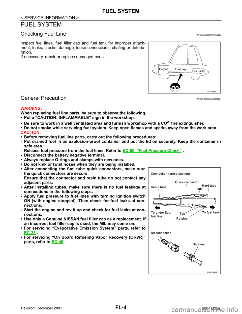
Inspect fuel lines, fuel filler cap and fuel tank for improper attach-
ment, leaks, cracks, damage, loose connections, chafing or deterio-
ration.
If necessary, repair or replace damaged parts.
General PrecautionINFOID:0000000003532204
WARNING:
When replacing fuel line parts, be sure to observe the following.
• Put a “CAUTION: INFLAMMABLE” sign in the workshop.
• Be sure to work in a well ventilated area and furnish workshop with a CO
2 fire extinguisher.
• Do not smoke while servicing fuel system. Keep open flames and sparks away from the work area.
CAUTION:
• Before removing fuel line parts, carry out the following procedures:
- Put drained fuel in an explosion-proof container and put the lid on securely. Keep the container in
safe area.
- Release fuel pressure from the fuel lines. Refer to EC-80, "
Fuel Pressure Check" .
- Disconnect the battery negative terminal.
• Always replace O-rings and clamps with new ones.
• Do not kink or twist hoses when they are being installed.
• After connecting the fuel tube quick connectors, make sure
the quick connectors are secure.
Ensure that the connector and resin tube do not contact any
adjacent parts.
• After installing tubes, make sure there is no fuel leakage at
connections in the following steps.
- Apply fuel pressure to fuel lines with turning ignition switch
ON (with engine stopped). Then check for fuel leaks at con-
nections.
- Start the engine and rev it up and check for fuel leaks at con-
nections.
• Use only a Genuine NISSAN fuel filler cap as a replacement. If
an incorrect fuel filler cap is used, the MIL may come on.
• For servicing “Evaporative Emission System” parts, refer to
EC-33
.
• For servicing “On Board Refueling Vapor Recovery (ORVR)”
parts, refer to EC-40
.
SMA803A
PBIC1268E
Page 2026 of 3061

SQUEAK AND RATTLE TROUBLE DIAGNOSIS
GW-7
< SERVICE INFORMATION >
C
D
E
F
G
H
J
K
L
MA
B
GW
N
O
P
SILICONE GREASE
Used instead of UHMW tape that will be visible or not fit.
Note: Will only last a few months.
SILICONE SPRAY
Use when grease cannot be applied.
DUCT TAPE
Use to eliminate movement.
CONFIRM THE REPAIR
Confirm that the cause of a noise is repaired by test driving the vehicle. Operate the vehicle under the same
conditions as when the noise originally occurred. Refer to the notes on the Diagnostic Worksheet.
Generic Squeak and Rattle TroubleshootingINFOID:0000000003533020
Refer to Table of Contents for specific component removal and installation information.
INSTRUMENT PANEL
Most incidents are caused by contact and movement between:
1. The cluster lid A and instrument panel
2. Acrylic lens and combination meter housing
3. Instrument panel to front pillar garnish
4. Instrument panel to windshield
5. Instrument panel mounting pins
6. Wiring harnesses behind the combination meter
7. A/C defroster duct and duct joint
These incidents can usually be located by tapping or moving the components to duplicate the noise or by
pressing on the components while driving to stop the noise. Most of these incidents can be repaired by apply-
ing felt cloth tape or silicone spray (in hard to reach areas). Urethane pads can be used to insulate wiring har-
ness.
CAUTION:
Do not use silicone spray to isolate a squeak or rattle. If you saturate the area with silicone, you will
not be able to recheck the repair.
CENTER CONSOLE
Components to pay attention to include:
1. Shifter assembly cover to finisher
2. A/C control unit and cluster lid C
3. Wiring harnesses behind audio and A/C control unit
The instrument panel repair and isolation procedures also apply to the center console.
DOORS
Pay attention to the:
1. Finisher and inner panel making a slapping noise
2. Inside handle escutcheon to door finisher
3. Wiring harnesses tapping
4. Door striker out of alignment causing a popping noise on starts and stops
Tapping or moving the components or pressing on them while driving to duplicate the conditions can isolate
many of these incidents. You can usually insulate the areas with felt cloth tape or insulator foam blocks from
the NISSAN Squeak and Rattle Kit (J-43980) to repair the noise.
TRUNK
Trunk noises are often caused by a loose jack or loose items put into the trunk by the owner.
In addition look for:
1. Trunk lid bumpers out of adjustment
2. Trunk lid striker out of adjustment
3. The trunk lid torsion bars knocking together
4. A loose license plate or bracket
Page 2037 of 3061
GW-18
< SERVICE INFORMATION >
POWER WINDOW SYSTEM
The signal is transmitted from main power window and door lock/unlock switch to power window and door
lock/unlock switch RH
• Front door window RH operation signal.
• Power window control by front door lock assembly LH (key cylinder switch) signal.
• Power window lock signal.
• Retained power operation signal.
• Rear power window operation.
POWER WINDOW LOCK
The power window lock is designed to lock operation of all windows except for front door window LH.
When in the lock position, the power window lock signal is transmitted to power window and door lock/unlock
switch RH by power window serial link. This prevents the power window motor from operating.
RETAINED POWER OPERATION
When the ignition switch is turned to the OFF position from ON or START position, power is supplied for 45
seconds
• to main power window and door lock/unlock switch terminal 10
• from BCM terminal 68.
When power and ground are supplied, the BCM continues to be energized, and the power window can be
operated.
The retained power operation is canceled when the front LH or front RH door is opened.
Retained power operation period can be changed by CONSULT-II. Refer to GW-31, "
CONSULT-II Function
(BCM)" .
ANTI-PINCH SYSTEM
Main power window and door lock/unlock switch, power window and door lock/unlock switch RH and rear
power window control unit LH and RH monitors the power window motor operation and the power window
position (full closed or other) for each power window by the signals from encoder and limit switch in power win-
dow motor.
When a window switch detects interruption during the following close operation,
• automatic close operation when ignition switch is in the ON position
• automatic close operation during retained power operation
Main power window and door lock/unlock switch, power window and door lock/unlock switch RH and rear
power window control unit LH and RH controls each power window motor for open and the power window will
be lowered about 150 mm (5.91 in).
POWER WINDOW CONTROL BY THE FRONT DOOR LOCK ASSEMBLY LH (KEY CYLINDER
SWITCH)
When ignition key switch is OFF, front power window LH and RH can be opened or closed by turning the front
door lock assembly LH (key cylinder switch) to the UNLOCK/LOCK position for more than 1 second.
• Front power windows can be opened as the front door lock assembly LH (key cylinder switch) is kept fully
turned to the UNLOCK position.
• Front power windows can be closed as the front door lock assembly LH (key cylinder switch) is kept fully
turned to the LOCK position.
• While performing open/close operation for the windows, power window is stopped when the front door lock
assembly LH (key cylinder switch) is placed in the NEUTRAL position.
• When the ignition switch is turned ON while the power window opening operation is performed, the power
window opening stops.
CAN Communication System DescriptionINFOID:0000000003533026
Refer to LAN-4.
Page 2111 of 3061
IDX-7
A
C
D
E
F
G
H
I
J
K
L B
IDX
ALPHABETICAL INDEX
Pressure switch 2 ............................................. AT-153
Pressure switch 3 ............................... AT-137, AT-157
Pressure switch 5 ............................... AT-145, AT-159
Pressure switch 6 ............................... AT-149, AT-161
Pressure test (A/T) ............................................. AT-52
Propeller shaft ........................................... PR-4, PR-8
Propeller shaft inspection .................................. MA-25
Propeller shaft on vehicle service ....................... PR-8
Propeller shaft vibration ............................ PR-4, PR-8
PS/SEN - Wiring diagram ................................ EC-471
R
R/VIEW - Wiring diagram .................................... DI-66
Radiator ............................................................. CO-14
Rear Audio Remote Control Unit ......................... AV-8
Rear axle ........................................................... RAX-5
Rear bumper ....................................................... EI-15
Rear case (Transfer) .......................... TF-148, TF-181
Rear combination lamp removal and installation ... LT-
101
Rear cover packing replacement diff. .............. RFD-28
Rear door ........................................... BL-117, GW-65
Rear seat belt ...................................................... SB-7
Rear suspension ............................................. RSU-23
Rear view monitor ............................................... DI-63
Rear washer .................................................... WW-29
Rear window defogger ..................................... GW-71
Rear wiper ....................................................... WW-29
Refrigerant connection precaution .................... ATC-6
Refrigerant discharging evacuating charging ATC-175
Refrigerant general precaution .......................... ATC-6
Refrigerant lines ........... ATC-175, ATC-183, ATC-184
Refrigerant pressure sensor ............ EC-692, ATC-184
Relay box .......................................................... PG-78
Remote keyless entry system ............................ BL-40
Removal and installation (A/T) ........... AT-238, AT-241
Removal and installation (Transfer) ................. TF-145
Ring gear diff. inspection ................................. RFD-18
Road wheel size ................................................. GI-51
Rocker cover ..................................................... EM-35
Room lamp ....................................................... LT-110
Room lamp - See Interior lamp ........................ LT-110
ROOM/L - Wiring diagram ................................ LT-116
RP/SEN - Wiring diagram ............................... EC-693
S
SAE J1979 - Service $01 - 09 ........................... EC-49
SEAT - Wiring diagram ..................................... SE-81
Seat belt inspection ............................... SB-12, MA-32
Seat belt pre-tensioner .................................... SRS-50
Seat belt, front ..................................................... SB-3
Seat belt, rear ...................................................... SB-7
Seat, front .......................................................... SE-89
Self-diagnosis (Transfer) .................................... TF-49
SEN/PW - Wiring diagram ............................... EC-483
SHIFT - Wiring diagram ................................... AT-217
Shift control (Transfer) ....................... TF-149, TF-176
Shift lock system .............................................. AT-216
Shock absorber (front) ..................................... FSU-11
Shock absorber (rear) ..................................... RSU-32
Side air bag (satellite) sensor .......................... SRS-49
Side curtain air bag .......................................... SRS-46
Side trim .............................................................. EI-35
SMJ (super multiple junction) ............................ PG-74
SONAR - Wiring diagram ................................... DI-53
Spare tire size ..................................................... GI-51
Spark plug ......................................................... EM-29
Specification value ........................................... EC-139
Speedometer ........................................................ DI-5
Spiral cable ...................................................... SRS-41
SROOF - Wiring diagram .................................. RF-13
SRS - See Supplemental Restraint System ...... SRS-5
SRS - Wiring diagram ...................................... SRS-13
SRS Trouble diagnoses ..................................... SRS-9
Stabilizer bar (front) ......................................... FSU-12
Stabilizer bar (rear) ......................................... RSU-39
Stall test (A/T) .................................................... AT-51
Standardized relay ............................................. PG-72
START - Wiring diagram ................................... SC-11
Starting system .................................................. SC-10
Steering gear, linkage and transfer gear inspection .....
MA-29
Steering linkage ................................................. PS-15
Steering wheel and column ................................. PS-7
Step lamp ......................................................... LT-111
Stop lamp ........................................................... LT-84
Stop lamp switch ................. EC-572, EC-584, EC-647
STOP/L - Wiring diagram ................................... LT-85
Strut (front) ...................................................... FSU-10
STSIG - Wiring diagram .................................... AT-97
Sub-oil pump (Transfer) ...................... TF-154, TF-167
Sun gear (Transfer) ............................ TF-149, TF-176
Sun roof, electric ................................................ RF-10
Sunload sensor .............................................. ATC-144
Sunroof .............................................................. RF-22
Supplemental Restraint System ........................ SRS-5
Supplemental restraint system - Wiring diagram . SRS-
13
Symbols and abbreviations ..................... GI-10, GI-23
Symptom matrix chart ........................................ EC-94
System readiness test (SRT) code .................... EC-55
T
Tachometer .......................................................... DI-5
Tail lamp ............................................................. LT-89
TAIL/L - Wiring diagram ...................................... LT-91
TCM circuit diagram .......................................... AT-50
TCS - Wiring diagram ..................................... BRC-16
TCS (traction control system) ........................... BRC-7
TCS component parts and connector location BRC-14
TCS wheel sensors ........................................ BRC-14
Telephone .......................................................... AV-62
Theft warning system - See Vehicle security (Theft warn-
ing) system ......................................................... BL-67
Thermometer ...................................................... DI-23
Page 2118 of 3061
IP-6
< SERVICE INFORMATION >
SQUEAK AND RATTLE TROUBLE DIAGNOSIS
SILICONE GREASE
Used in place of UHMW tape that will be visible or not fit.
Note: Will only last a few months.
SILICONE SPRAY
Use when grease cannot be applied.
DUCT TAPE
Use to eliminate movement.
CONFIRM THE REPAIR
Confirm that the cause of a noise is repaired by test driving the vehicle. Operate the vehicle under the same
conditions as when the noise originally occurred. Refer to the notes on the Diagnostic Worksheet.
Generic Squeak and Rattle TroubleshootingINFOID:0000000003533145
Refer to Table of Contents for specific component removal and installation information.
INSTRUMENT PANEL
Most incidents are caused by contact and movement between:
1. The cluster lid A and instrument panel
2. Acrylic lens and combination meter housing
3. Instrument panel to front pillar garnish
4. Instrument panel to windshield
5. Instrument panel mounting pins
6. Wiring harnesses behind the combination meter
7. A/C defroster duct and duct joint
These incidents can usually be located by tapping or moving the components to duplicate the noise or by
pressing on the components while driving to stop the noise. Most of these incidents can be repaired by apply-
ing felt cloth tape or silicone spray (in hard to reach areas). Urethane pads can be used to insulate wiring har-
ness.
CAUTION:
Do not use silicone spray to isolate a squeak or rattle. If you saturate the area with silicone, you will
not be able to recheck the repair.
CENTER CONSOLE
Components to pay attention to include:
1. Shifter assembly cover to finisher
2. A/C control unit and cluster lid C
3. Wiring harnesses behind audio and A/C control unit
The instrument panel repair and isolation procedures also apply to the center console.
DOORS
Pay attention to the:
1. Finisher and inner panel making a slapping noise
2. Inside handle escutcheon to door finisher
3. Wiring harnesses tapping
4. Door striker out of alignment causing a popping noise on starts and stops
Tapping or moving the components or pressing on them while driving to duplicate the conditions can isolate
many of these incidents. You can usually insulate the areas with felt cloth tape or insulator foam blocks from
the NISSAN Squeak and Rattle Kit (J-43980) to repair the noise.
TRUNK
Trunk noises are often caused by a loose jack or loose items put into the trunk by the owner.
In addition look for:
1. Trunk lid bumpers out of adjustment
2. Trunk lid striker out of adjustment
3. The trunk lid torsion bars knocking together
4. A loose license plate or bracket
Page 2232 of 3061
HEADLAMP (FOR CANADA) - DAYTIME LIGHT SYSTEM -
LT-25
< SERVICE INFORMATION >
C
D
E
F
G
H
I
J
L
MA
B
LT
N
O
P
lamps turn off when lighting switch is in the 2ND position or AUTO position (Headlamp is "ON") and when light-
ing switch is in the PASSING position. (Daytime light lamps are not turned off only by parking brake itself.)
A parking brake signal and engine run or stop signal are sent to BCM (body control module) by CAN commu-
nication line.
OUTLINE
Power is supplied at all times
• to ignition relay, located in the IPDM E/R (intelligent power distribution module engine room),
• through 50A fusible link (letter f , located in the fuse and fusible link box)
• to BCM terminal 70,
• through 20A fuse (No. 53, located in the IPDM E/R)
• to CPU (central processing unit) of the IPDM E/R,
• through 10A fuse [No. 19, located in the fuse block (J/B)]
• to combination meter terminal 8, and
• through 10A fuse (No. 45, located in the IPDM E/R)
• to daytime light relay terminals 2 and 5.
When the ignition switch is in ON or START position, power is supplied
• to ignition relay, located in the IPDM E/R,
• through 10A fuse (No. 59, located in the fuse and relay box)
• to BCM terminal 38, and
• through 10A fuse [No. 14, located in the fuse block (J/B)]
• to combination meter terminal 24.
Ground is supplied
• to BCM terminal 67 and
• to combination meter terminal 17
• through grounds M57, M61 and M79.
DAYTIME LIGHT OPERATION
With the engine running, the lighting switch in the OFF or 1ST position and parking brake released, the IPDM
E/R receives input requesting the daytime lights illuminate. This input is communicated across the CAN com-
munication lines. The CPU of the IPDM E/R controls the daytime light relay coil. When energized, this relay
directs power
• through daytime light relay terminal 3
• to front combination lamp LH terminal 2
• through front combination lamp LH terminal 6
• to IPDM E/R terminal 55
• through 10A fuse (No. 35, located in the IPDM E/R)
• through 10A fuse (No. 34, located in the IPDM E/R)
• through IPDM E/R terminal 56
• to front combination lamp RH terminal 6.
Ground is supplied
• to front combination lamp RH terminal 2
• through grounds E9, E15 and E24.
With power and ground supplied, the daytime lights illuminate. The high beam headlamps are now wired in
series and illuminate at a reduced intensity.
COMBINATION SWITCH READING FUNCTION
Refer to BCS-3, "System Description" .
AUTO LIGHT OPERATION
Refer to LT-34, "System Description" .
CAN Communication System DescriptionINFOID:0000000003533355
Refer to LAN-4, "CAN Communication System" .
Page 2242 of 3061
AUTO LIGHT SYSTEM
LT-35
< SERVICE INFORMATION >
C
D
E
F
G
H
I
J
L
MA
B
LT
N
O
P
OUTLINE
The auto light control system uses an optical sensor that detects outside brightness.
When the lighting switch is in "AUTO" position, it automatically turns on/off the parking lamps and the head-
lamps in accordance with the ambient light. Sensitivity can be adjusted in four steps. For the details of the set-
ting, refer to LT-40, "
Preliminary Check" .
Optical sensor ground is supplied
• to optical sensor terminal 3
• through BCM (body control module) terminal 18.
When ignition switch is turned to “ON” position and when outside brightness is darker than prescribed level,
input is supplied
• to BCM terminal 58
• through optical sensor terminal 4.
The headlamps will then illuminate. For a description of headlamp operation, refer to LT- 5 , "
System Descrip-
tion" .
COMBINATION SWITCH READING FUNCTION
Refer to BCS-3, "System Description" .
EXTERIOR LAMP BATTERY SAVER CONTROL
When the combination switch (lighting switch) is in the AUTO position, and the ignition switch is turned from
ON or ACC to OFF, and one of the front doors is opened, the battery saver control feature is activated.
Under this condition, the headlamps remain illuminated for 5 minutes, then the headlamps are turned off.
Exterior lamp battery saver control mode can be changed by the function setting of CONSULT-II.
DELAY TIMER FUNCTION
When the ignition switch is ON and auto light switch is ON, the BCM turns on/off the headlamps. In delay timer
function, ignition is OFF, auto light sensor power source is OFF and the headlamps are not turned on/off by the
BCM. On condition that:
• when the state of ignition switch ON or ACC is ON and output judgment by auto light function is headlamp
ON changes to ignition switch and ACC are OFF and any door switch is ON, output judgment by BCM
should be headlamp ON for 5 minutes by timer. After time out, output judgment by BCM should be headlamp
OFF.
• when the state of any door switch is turned to ON from OFF while 45 second or 5 minute timer is counting,
timer stops, and restarts counting for 5 minutes, then BCM judges output as headlamp ON. After time out,
BCM judges output as headlamp OFF.
• when the state of front door switch (LH), front door switch (RH), rear door switch LH, rear door switch RH or
back door latch (door ajar switch) is ON turns to all door switches are OFF while 45 second or 5 minute timer
is counting, timer stops, and restarts counting for 45 seconds, then BCM judges output as headlamp ON.
After timer out, BCM judges output as headlamp OFF.
• when the state is ignition switch ON or ACC is ON or auto light switch OFF while timer is counting, timer
stops counting and BCM turns on/off lamps according to headlamp function, front fog lamp function, auto
light function and headlamp battery save function.
Delay timer control mode can be changed by the function setting of CONSULT-II.
CAN Communication System DescriptionINFOID:0000000003533370
Refer to LAN-4, "CAN Communication System" .
Major Component and FunctionsINFOID:0000000003533371
Components Functions
BCM• Turns on/off circuits of tail light and headlamp according to signals from light sensor, lighting switch
(AUTO), front door switch LH, front door switch RH, rear door switch, back door latch (door ajar
switch), and ignition switch (ON, OFF).
Optical sensor • Converts ambient light (lux) to voltage, and sends it to BCM. (Detects lightness of 50 to 1,300 lux)
Page 2271 of 3061

LT-64
< SERVICE INFORMATION >
TURN SIGNAL AND HAZARD WARNING LAMPS
3. Perform preliminary check. Refer to LT-64, "Preliminary Check" .
4. Check symptom and repair or replace the component.
5. Do turn signal and hazard warning lamps operate normally? If YES: GO TO 6. If NO: GO TO 4.
6. Inspection End.
Preliminary CheckINFOID:0000000003533410
CHECK POWER SUPPLY AND GROUND CIRCUIT FOR BCM
Refer to BCS-15, "BCM Power Supply and Ground Circuit Inspection".
CONSULT-II Function (BCM)INFOID:0000000003533411
Refer to BCS-16, "CONSULT-II Function (BCM)".
CONSULT-II START PROCEDURE
Refer to GI-36, "CONSULT-II Start Procedure".
DATA MONITOR
Display Item List
ACTIVE TEST
Display Item List
Front Turn Signal Lamp Does Not OperateINFOID:0000000003533412
1.CHECK COMBINATION SWITCH INPUT SIGNAL
With CONSULT-II
Select "BCM" on CONSULT-II. With "FLASHER" data monitor, make
sure "TURN SIGNAL R" and "TURN SIGNAL L" turns ON-OFF
linked with operation of lighting switch.
Without CONSULT-II
Refer to LT-73, "
Combination Switch Inspection" .
OK or NG
OK >> GO TO 2.
NG >> Check lighting switch. Refer to LT-73, "
Combination Switch Inspection".
2.ACTIVE TEST
With CONSULT-II
Monitor item Contents
IGN ON SW "ON/OFF" Displays "IGN position (ON)/OFF, ACC position (OFF)" judged from the ignition switch signal.
HAZARD SW "ON/OFF" Displays "Hazard ON (ON)/Hazard OFF (OFF)" status, determined from hazard switch signal.
TURN SIGNAL R "ON/OFF" Displays "Turn right (ON)/Other (OFF)" status, determined from lighting switch signal.
TURN SIGNAL L "ON/OFF" Displays "Turn left (ON)/Other (OFF)" status, determined from lighting switch signal.
BRAKE SW "ON/OFF" Displays status of stop lamp switch.
Test item Description
FLASHER (RH) Turn signal lamp (right) can be operated by any ON-OFF operations.
FLASHER (LH) Turn signal lamp (left) can be operated by any ON-OFF operations.
When lighting switch is in
TURN RH position: TURN SIGNAL R ON
When lighting switch is in
TURN LH position: TURN SIGNAL L ON
SKIA4499E