2007 INFINITI QX56 stop start
[x] Cancel search: stop startPage 1385 of 3061
EC-302
< SERVICE INFORMATION >
DTC P0172, P0175 FUEL INJECTION SYSTEM FUNCTION
7. If it is difficult to start engine at step 6, the fuel injection system has a malfunction, too.
8. Crank engine while depressing accelerator pedal.
If engine starts, go to EC-306, "
Diagnosis Procedure". If engine does not start, remove spark plugs and
check for fouling, etc.
WITH GST
1. Start engine and warm it up to normal operating temperature.
2. Turn ignition switch OFF and wait at least 10 seconds.
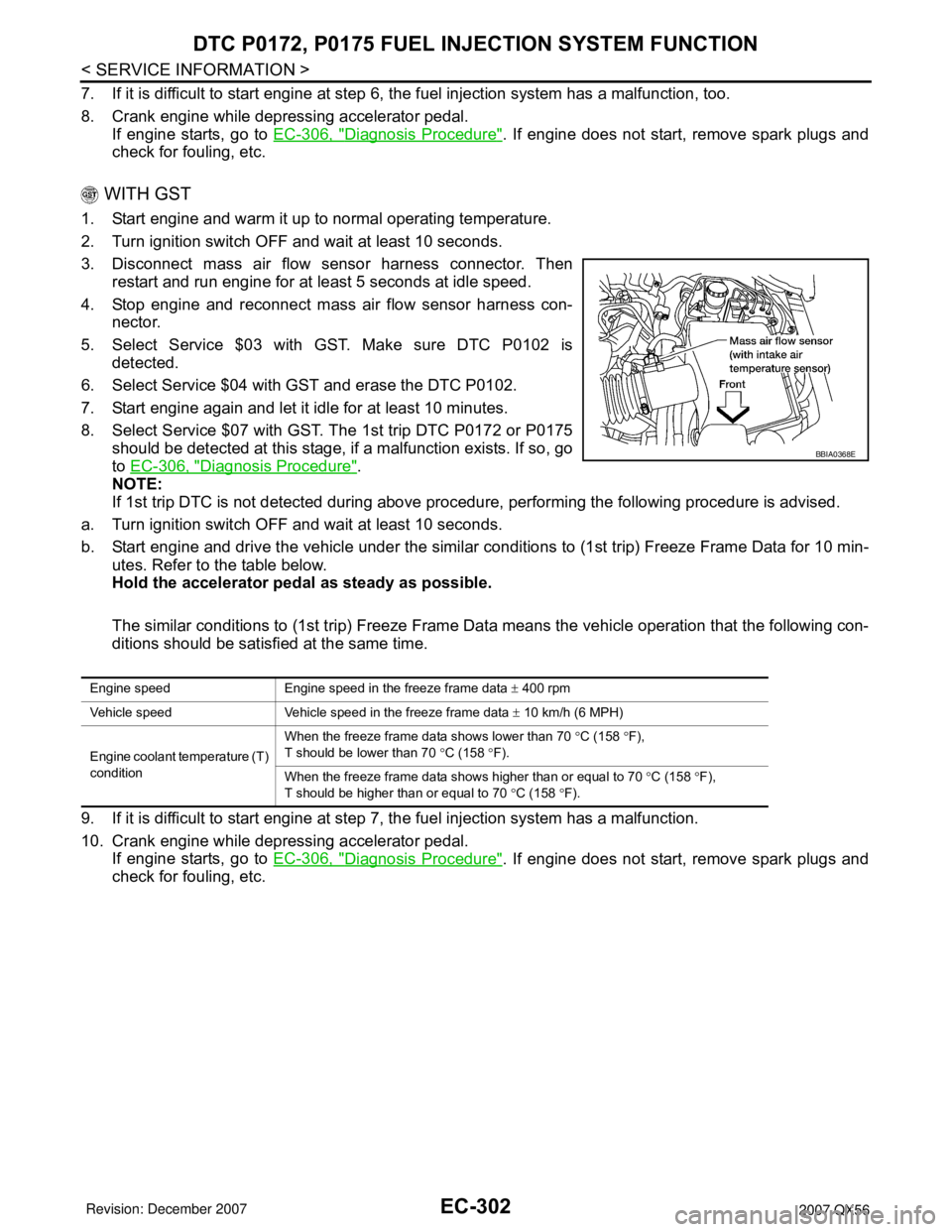
3. Disconnect mass air flow sensor harness connector. Then
restart and run engine for at least 5 seconds at idle speed.
4. Stop engine and reconnect mass air flow sensor harness con-
nector.
5. Select Service $03 with GST. Make sure DTC P0102 is
detected.
6. Select Service $04 with GST and erase the DTC P0102.
7. Start engine again and let it idle for at least 10 minutes.
8. Select Service $07 with GST. The 1st trip DTC P0172 or P0175
should be detected at this stage, if a malfunction exists. If so, go
to EC-306, "
Diagnosis Procedure".
NOTE:
If 1st trip DTC is not detected during above procedure, performing the following procedure is advised.
a. Turn ignition switch OFF and wait at least 10 seconds.
b. Start engine and drive the vehicle under the similar conditions to (1st trip) Freeze Frame Data for 10 min-
utes. Refer to the table below.
Hold the accelerator pedal as steady as possible.
The similar conditions to (1st trip) Freeze Frame Data means the vehicle operation that the following con-
ditions should be satisfied at the same time.
9. If it is difficult to start engine at step 7, the fuel injection system has a malfunction.
10. Crank engine while depressing accelerator pedal.
If engine starts, go to EC-306, "
Diagnosis Procedure". If engine does not start, remove spark plugs and
check for fouling, etc.
BBIA0368E
Engine speed Engine speed in the freeze frame data ± 400 rpm
Vehicle speed Vehicle speed in the freeze frame data ± 10 km/h (6 MPH)
Engine coolant temperature (T)
conditionWhen the freeze frame data shows lower than 70 °C (158 °F),
T should be lower than 70 °C (158 °F).
When the freeze frame data shows higher than or equal to 70 °C (158 °F),
T should be higher than or equal to 70 °C (158 °F).
Page 1409 of 3061
EC-326
< SERVICE INFORMATION >
DTC P0300 - P0308 MULTIPLE CYLINDER MISFIRE, NO. 1 - 8 CYLINDER MIS-
FIRE
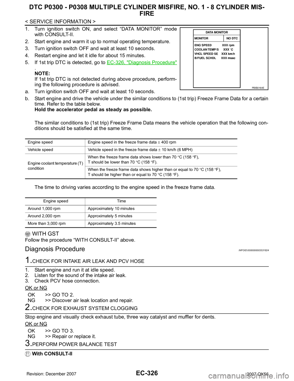
1. Turn ignition switch ON, and select “DATA MONITOR” mode
with CONSULT-II.
2. Start engine and warm it up to normal operating temperature.
3. Turn ignition switch OFF and wait at least 10 seconds.
4. Restart engine and let it idle for about 15 minutes.
5. If 1st trip DTC is detected, go to EC-326, "
Diagnosis Procedure"
.
NOTE:
If 1st trip DTC is not detected during above procedure, perform-
ing the following procedure is advised.
a. Turn ignition switch OFF and wait at least 10 seconds.
b. Start engine and drive the vehicle under the similar conditions to (1st trip) Freeze Frame Data for a certain
time. Refer to the table below.
Hold the accelerator pedal as steady as possible.
The similar conditions to (1st trip) Freeze Frame Data means the vehicle operation that the following con-
ditions should be satisfied at the same time.
The time to driving varies according to the engine speed in the freeze frame data.
WITH GST
Follow the procedure “WITH CONSULT-II” above.
Diagnosis ProcedureINFOID:0000000003531824
1.CHECK FOR INTAKE AIR LEAK AND PCV HOSE
1. Start engine and run it at idle speed.
2. Listen for the sound of the intake air leak.
3. Check PCV hose connection.
OK or NG
OK >> GO TO 2.
NG >> Discover air leak location and repair.
2.CHECK FOR EXHAUST SYSTEM CLOGGING
Stop engine and visually check exhaust tube, three way catalyst and muffler for dents.
OK or NG
OK >> GO TO 3.
NG >> Repair or replace it.
3.PERFORM POWER BALANCE TEST
With CONSULT-II
PBIB0164E
Engine speed Engine speed in the freeze frame data ± 400 rpm
Vehicle speed Vehicle speed in the freeze frame data ± 10 km/h (6 MPH)
Engine coolant temperature (T)
conditionWhen the freeze frame data shows lower than 70 °C (158 °F),
T should be lower than 70 °C (158 °F).
When the freeze frame data shows higher than or equal to 70 °C (158 °F),
T should be higher than or equal to 70 °C (158 °F).
Engine speed Time
Around 1,000 rpm Approximately 10 minutes
Around 2,000 rpm Approximately 5 minutes
More than 3,000 rpm Approximately 3.5 minutes
Page 1433 of 3061
EC-350
< SERVICE INFORMATION >
DTC P0420, P0430 THREE WAY CATALYST FUNCTION
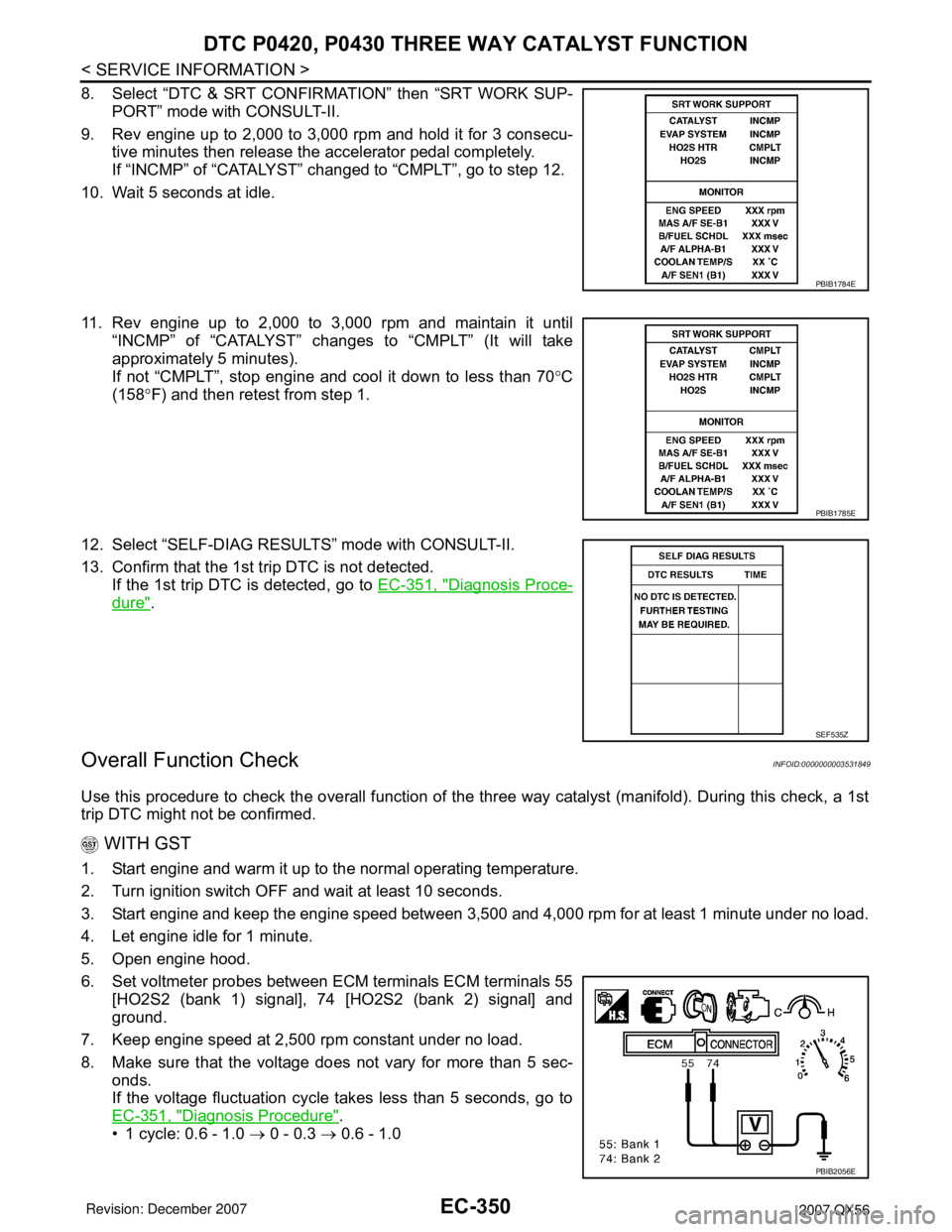
8. Select “DTC & SRT CONFIRMATION” then “SRT WORK SUP-
PORT” mode with CONSULT-II.
9. Rev engine up to 2,000 to 3,000 rpm and hold it for 3 consecu-
tive minutes then release the accelerator pedal completely.
If “INCMP” of “CATALYST” changed to “CMPLT”, go to step 12.
10. Wait 5 seconds at idle.
11. Rev engine up to 2,000 to 3,000 rpm and maintain it until
“INCMP” of “CATALYST” changes to “CMPLT” (It will take
approximately 5 minutes).
If not “CMPLT”, stop engine and cool it down to less than 70°C
(158°F) and then retest from step 1.
12. Select “SELF-DIAG RESULTS” mode with CONSULT-II.
13. Confirm that the 1st trip DTC is not detected.
If the 1st trip DTC is detected, go to EC-351, "
Diagnosis Proce-
dure".
Overall Function CheckINFOID:0000000003531849
Use this procedure to check the overall function of the three way catalyst (manifold). During this check, a 1st
trip DTC might not be confirmed.
WITH GST
1. Start engine and warm it up to the normal operating temperature.
2. Turn ignition switch OFF and wait at least 10 seconds.
3. Start engine and keep the engine speed between 3,500 and 4,000 rpm for at least 1 minute under no load.
4. Let engine idle for 1 minute.
5. Open engine hood.
6. Set voltmeter probes between ECM terminals ECM terminals 55
[HO2S2 (bank 1) signal], 74 [HO2S2 (bank 2) signal] and
ground.
7. Keep engine speed at 2,500 rpm constant under no load.
8. Make sure that the voltage does not vary for more than 5 sec-
onds.
If the voltage fluctuation cycle takes less than 5 seconds, go to
EC-351, "
Diagnosis Procedure".
• 1 cycle: 0.6 - 1.0 → 0 - 0.3 → 0.6 - 1.0
PBIB1784E
PBIB1785E
SEF535Z
PBIB2056E
Page 1434 of 3061
DTC P0420, P0430 THREE WAY CATALYST FUNCTION
EC-351
< SERVICE INFORMATION >
C
D
E
F
G
H
I
J
K
L
MA
EC
N
P O
Diagnosis ProcedureINFOID:0000000003531850
1.CHECK EXHAUST SYSTEM
Visually check exhaust tubes and muffler for dent.
OK or NG
OK >> GO TO 2.
NG >> Repair or replace.
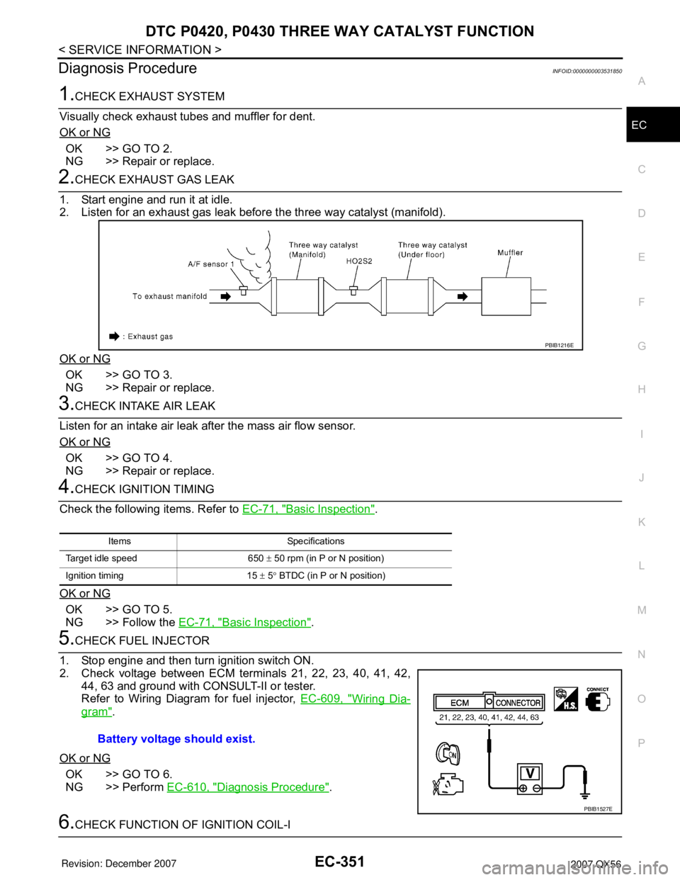
2.CHECK EXHAUST GAS LEAK
1. Start engine and run it at idle.
2. Listen for an exhaust gas leak before the three way catalyst (manifold).
OK or NG
OK >> GO TO 3.
NG >> Repair or replace.
3.CHECK INTAKE AIR LEAK
Listen for an intake air leak after the mass air flow sensor.
OK or NG
OK >> GO TO 4.
NG >> Repair or replace.
4.CHECK IGNITION TIMING
Check the following items. Refer to EC-71, "
Basic Inspection".
OK or NG
OK >> GO TO 5.
NG >> Follow the EC-71, "
Basic Inspection".
5.CHECK FUEL INJECTOR
1. Stop engine and then turn ignition switch ON.
2. Check voltage between ECM terminals 21, 22, 23, 40, 41, 42,
44, 63 and ground with CONSULT-II or tester.
Refer to Wiring Diagram for fuel injector, EC-609, "
Wiring Dia-
gram".
OK or NG
OK >> GO TO 6.
NG >> Perform EC-610, "
Diagnosis Procedure".
6.CHECK FUNCTION OF IGNITION COIL-I
PBIB1216E
Items Specifications
Target idle speed 650 ± 50 rpm (in P or N position)
Ignition timing 15 ± 5° BTDC (in P or N position)
Battery voltage should exist.
PBIB1527E
Page 1439 of 3061
EC-356
< SERVICE INFORMATION >
DTC P0441 EVAP CONTROL SYSTEM
Diagnosis Procedure
INFOID:0000000003531855
1.CHECK EVAP CANISTER
1. Turn ignition switch OFF.
2. Check EVAP canister for cracks.
OK or NG
OK (With CONSULT-II)>>GO TO 2.
OK (Without CONSULT-II)>>GO TO 3.
NG >> Replace EVAP canister.
2.CHECK PURGE FLOW
With CONSULT-II
1. Disconnect vacuum hose connected to EVAP canister purge volume control solenoid valve at EVAP ser-
vice port and install vacuum gauge. For the location of EVAP service port, refer to EC-33, "
Description".
2. Start engine and let it idle.
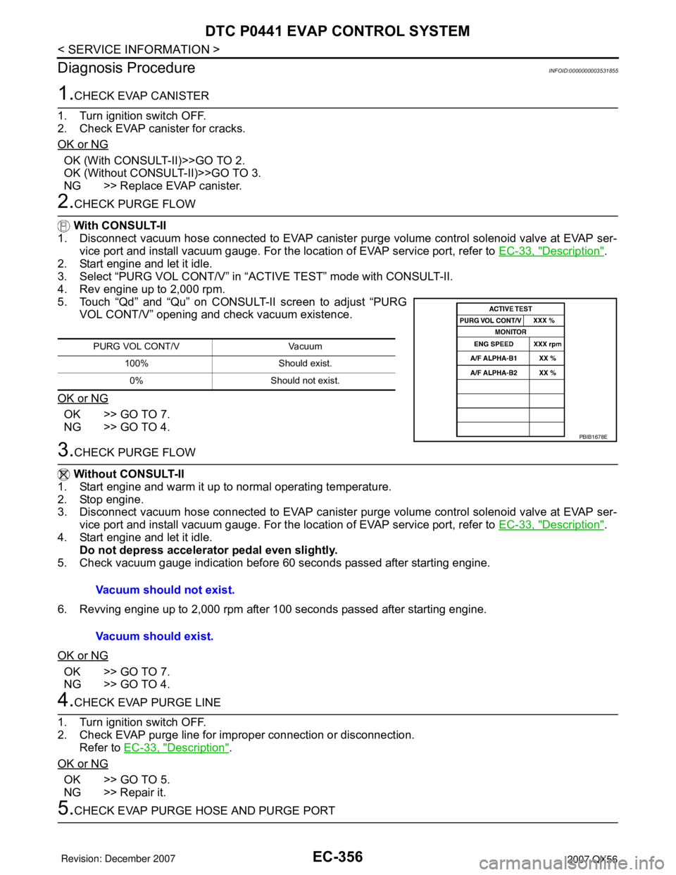
3. Select “PURG VOL CONT/V” in “ACTIVE TEST” mode with CONSULT-II.
4. Rev engine up to 2,000 rpm.
5. Touch “Qd” and “Qu” on CONSULT-II screen to adjust “PURG
VOL CONT/V” opening and check vacuum existence.
OK or NG
OK >> GO TO 7.
NG >> GO TO 4.
3.CHECK PURGE FLOW
Without CONSULT-II
1. Start engine and warm it up to normal operating temperature.
2. Stop engine.
3. Disconnect vacuum hose connected to EVAP canister purge volume control solenoid valve at EVAP ser-
vice port and install vacuum gauge. For the location of EVAP service port, refer to EC-33, "
Description".
4. Start engine and let it idle.
Do not depress accelerator pedal even slightly.
5. Check vacuum gauge indication before 60 seconds passed after starting engine.
6. Revving engine up to 2,000 rpm after 100 seconds passed after starting engine.
OK or NG
OK >> GO TO 7.
NG >> GO TO 4.
4.CHECK EVAP PURGE LINE
1. Turn ignition switch OFF.
2. Check EVAP purge line for improper connection or disconnection.
Refer to EC-33, "
Description".
OK or NG
OK >> GO TO 5.
NG >> Repair it.
5.CHECK EVAP PURGE HOSE AND PURGE PORT
PURG VOL CONT/V Vacuum
100% Should exist.
0% Should not exist.
PBIB1678E
Vacuum should not exist.
Vacuum should exist.
Page 1443 of 3061
EC-360
< SERVICE INFORMATION >
DTC P0442 EVAP CONTROL SYSTEM
• If DTC Confirmation Procedure has been previously conducted, always turn ignition switch OFF and wait at
least 10 seconds before conducting the next test.
TESTING CONDITION:
•Perform “DTC WORK SUPPORT” when the fuel level is between 1/4 and 3/4 full, and vehicle is placed
on flat level surface.
•Always perform test at a temperature of 0 to 30°C (32 to 86°F).
WITH CONSULT-II
1. Turn ignition switch ON.
2. Turn ignition switch OFF and wait at least 10 seconds.
3. Turn ignition switch ON and select “DATA MONITOR” mode with CONSULT-II.
4. Make sure that the following conditions are met.
COOLAN TEMP/S: 0 - 70°C (32 - 158°F)
INT/A TEMP SE: 0 - 30°C (32 - 86°F)
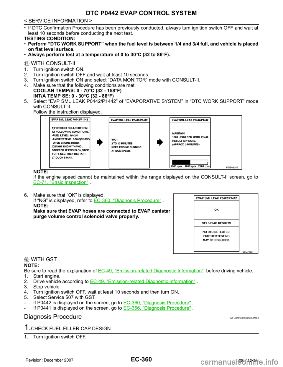
5. Select “EVP SML LEAK P0442/P1442” of “EVAPORATIVE SYSTEM” in “DTC WORK SUPPORT” mode
with CONSULT-II.
Follow the instruction displayed.
NOTE:
If the engine speed cannot be maintained within the range displayed on the CONSULT-II screen, go to
EC-71, "
Basic Inspection" .
6. Make sure that “OK” is displayed.
If “NG” is displayed, refer to EC-360, "
Diagnosis Procedure" .
NOTE:
Make sure that EVAP hoses are connected to EVAP canister
purge volume control solenoid valve properly.
WITH GST
NOTE:
Be sure to read the explanation of EC-49, "
Emission-related Diagnostic Information" before driving vehicle.
1. Start engine.
2. Drive vehicle according to EC-49, "
Emission-related Diagnostic Information" .
3. Stop vehicle.
4. Turn ignition switch OFF, wait at least 10 seconds and then turn ON.
5. Select Service $07 with GST.
- If P0442 is displayed on the screen, go to EC-360, "
Diagnosis Procedure" .
- If P0441 is displayed on the screen, go to EC-356, "
Diagnosis Procedure" .
Diagnosis ProcedureINFOID:0000000003531858
1.CHECK FUEL FILLER CAP DESIGN
1. Turn ignition switch OFF.
PBIB0829E
SEC763C
Page 1447 of 3061
EC-364
< SERVICE INFORMATION >
DTC P0442 EVAP CONTROL SYSTEM
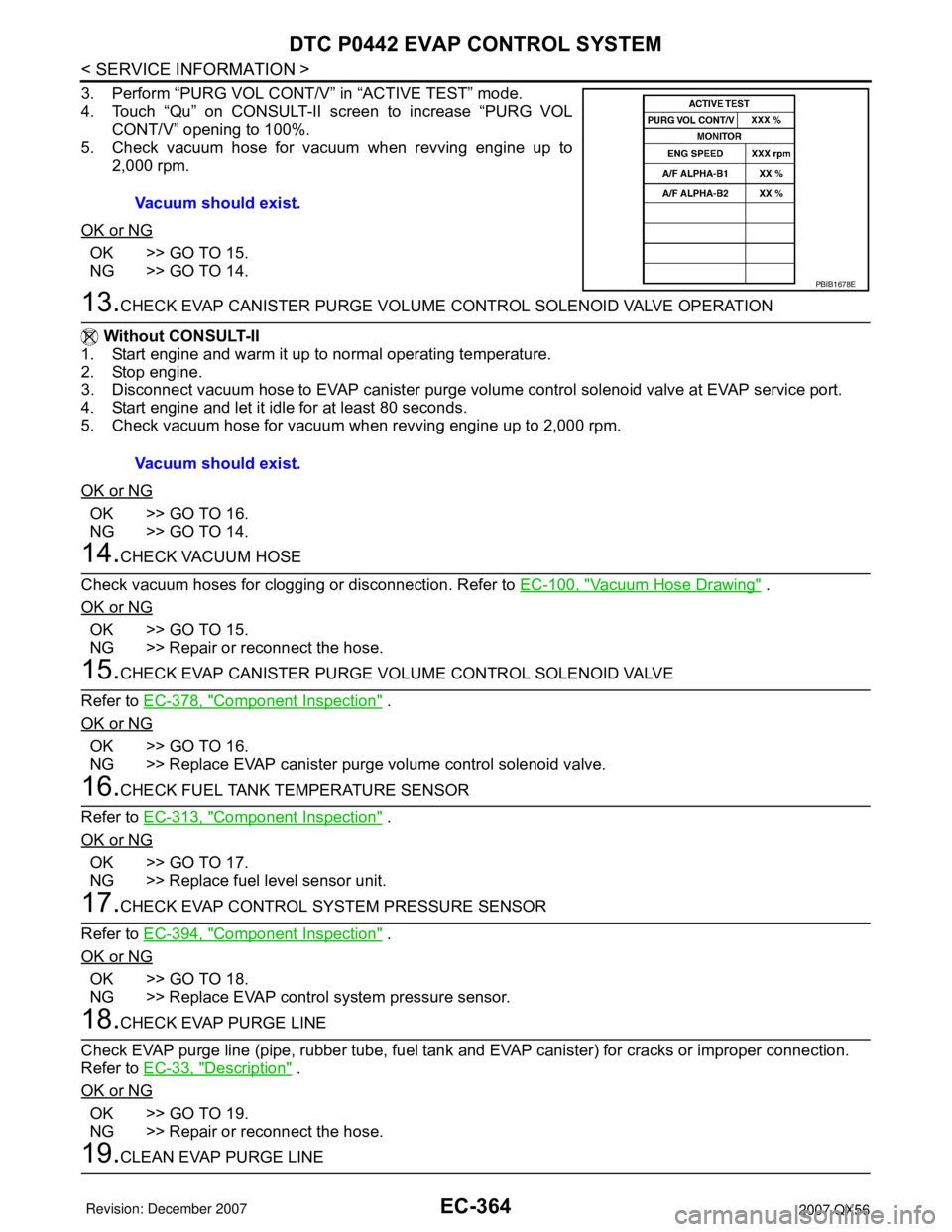
3. Perform “PURG VOL CONT/V” in “ACTIVE TEST” mode.
4. Touch “Qu” on CONSULT-II screen to increase “PURG VOL
CONT/V” opening to 100%.
5. Check vacuum hose for vacuum when revving engine up to
2,000 rpm.
OK or NG
OK >> GO TO 15.
NG >> GO TO 14.
13.CHECK EVAP CANISTER PURGE VOLUME CONTROL SOLENOID VALVE OPERATION
Without CONSULT-II
1. Start engine and warm it up to normal operating temperature.
2. Stop engine.
3. Disconnect vacuum hose to EVAP canister purge volume control solenoid valve at EVAP service port.
4. Start engine and let it idle for at least 80 seconds.
5. Check vacuum hose for vacuum when revving engine up to 2,000 rpm.
OK or NG
OK >> GO TO 16.
NG >> GO TO 14.
14.CHECK VACUUM HOSE
Check vacuum hoses for clogging or disconnection. Refer to EC-100, "
Vacuum Hose Drawing" .
OK or NG
OK >> GO TO 15.
NG >> Repair or reconnect the hose.
15.CHECK EVAP CANISTER PURGE VOLUME CONTROL SOLENOID VALVE
Refer to EC-378, "
Component Inspection" .
OK or NG
OK >> GO TO 16.
NG >> Replace EVAP canister purge volume control solenoid valve.
16.CHECK FUEL TANK TEMPERATURE SENSOR
Refer to EC-313, "
Component Inspection" .
OK or NG
OK >> GO TO 17.
NG >> Replace fuel level sensor unit.
17.CHECK EVAP CONTROL SYSTEM PRESSURE SENSOR
Refer to EC-394, "
Component Inspection" .
OK or NG
OK >> GO TO 18.
NG >> Replace EVAP control system pressure sensor.
18.CHECK EVAP PURGE LINE
Check EVAP purge line (pipe, rubber tube, fuel tank and EVAP canister) for cracks or improper connection.
Refer to EC-33, "
Description" .
OK or NG
OK >> GO TO 19.
NG >> Repair or reconnect the hose.
19.CLEAN EVAP PURGE LINEVacuum should exist.
PBIB1678E
Vacuum should exist.
Page 1492 of 3061
DTC P0455 EVAP CONTROL SYSTEM
EC-409
< SERVICE INFORMATION >
C
D
E
F
G
H
I
J
K
L
MA
EC
N
P O
•Make sure that EVAP hoses are connected to EVAP canister purge volume control solenoid valve
properly.
• If DTC Confirmation Procedure has been previously conducted, always turn ignition switch OFF and wait at
least 10 seconds before conducting the next test.
TESTING CONDITION:
•Perform “DTC WORK SUPPORT” when the fuel level is between 1/4 and 3/4 full, and vehicle is placed
on flat level surface.
•Open engine hood before conducting the following procedures.
WITH CONSULT-II
1. Tighten fuel filler cap securely until ratcheting sound is heard.
2. Turn ignition switch ON.
3. Turn ignition switch OFF and wait at least 10 seconds.
4. Turn ignition switch ON and select “DATA MONITOR” mode with CONSULT-II.
5. Make sure that the following conditions are met.
COOLAN TEMP/S: 0 - 70°C (32 - 158°F)
INT/A TEMP SE: 0 - 60°C (32 - 140°F)
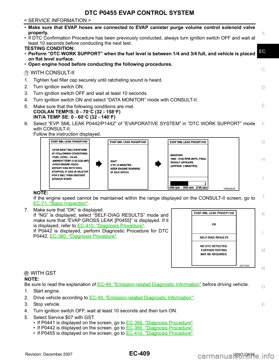
6. Select “EVP SML LEAK P0442/P1442” of “EVAPORATIVE SYSTEM” in “DTC WORK SUPPORT” mode
with CONSULT-II.
Follow the instruction displayed.
NOTE:
If the engine speed cannot be maintained within the range displayed on the CONSULT-II screen, go to
EC-71, "
Basic Inspection".
7. Make sure that “OK” is displayed.
If “NG” is displayed, select “SELF-DIAG RESULTS” mode and
make sure that “EVAP GROSS LEAK [P0455]” is displayed. If it
is displayed, refer to EC-410, "
Diagnosis Procedure".
If P0442 is displayed, perform Diagnostic Procedure for DTC
P0442, EC-360, "
Diagnosis Procedure".
WITH GST
NOTE:
Be sure to read the explanation of EC-49, "
Emission-related Diagnostic Information" before driving vehicle.
1. Start engine.
2. Drive vehicle according to EC-49, "
Emission-related Diagnostic Information".
3. Stop vehicle.
4. Turn ignition switch OFF, wait at least 10 seconds and then turn ON.
5. Select Service $07 with GST.
• If P0441 is displayed on the screen, go to EC-356, "
Diagnosis Procedure".
• If P0442 is displayed on the screen, go to EC-360, "
Diagnosis Procedure".
• If P0455 is displayed on the screen, go to EC-410, "
Diagnosis Procedure".
PBIB0829E
SEC763C