2007 INFINITI QX56 stop start
[x] Cancel search: stop startPage 1022 of 3061
COMBINATION METERSDI-11
< SERVICE INFORMATION >
C
DE
F
G H
I
J
L
M A
B
DI
N
O P
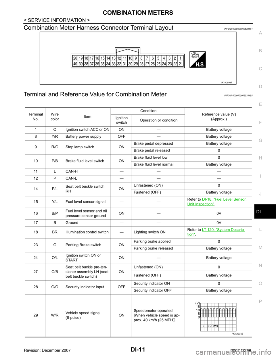
Combination Meter Harness Connector Terminal LayoutINFOID:0000000003533484
Terminal and Reference Va lue for Combination MeterINFOID:0000000003533485
LKIA0698E
Te r m i n a l
No. Wire
color Item Condition
Reference value (V)
(Approx.)
Ignition
switch Operation or condition
1 O Ignition switch ACC or ON ON — Battery voltage
8 Y/R Battery power supply OFF — Battery voltage
9 R/G Stop lamp switch ON Brake pedal depressed Battery voltage
Brake pedal released 0
10 P/B Brake fluid level switch ON Brake fluid level low 0
Brake fluid level normal Battery voltage
11 L C A N - H — — —
12 P CAN-L — — —
14 P/L Seat belt buckle switch
RH ONUnfastened (ON) 0
Fastened (OFF) Battery voltage
15 Y/L Fuel level sensor signal — — Refer to
DI-18, "
Fuel Level Sensor
Unit Inspection".
16 B/P Fuel level sensor and oil
pressure sensor ground ON — 0V
17 B Ground — — 0V
18 BR Illumination control switch — Lighting switch ON Refer to
LT- 1 2 0 , "
System Descrip-
tion".
23 G Parking Brake switch ON Parking brake applied 0
Parking brake released Battery voltage
24 O/L Ignition switch ON or
START ON — Battery voltage
27 O/B Seat belt buckle pre-ten-
sioner assembly LH (seat
belt buckle switch) ON
Unfastened (ON) 0
Fastened (OFF) Battery voltage
28 G/O Security indicator input OFF Security indicator ON 0
Security indicator
OFF Battery voltage
29 W/R Vehicle speed signal
(8-pulse) ONSpeedometer operated
[When vehicle speed is ap-
prox. 40 km/h (25 MPH)]
PKIA1935E
Page 1036 of 3061
COMPASS AND THERMOMETER
DI-25
< SERVICE INFORMATION >
C
D
E
F
G
H
I
J
L
MA
B
DI
N
O
P
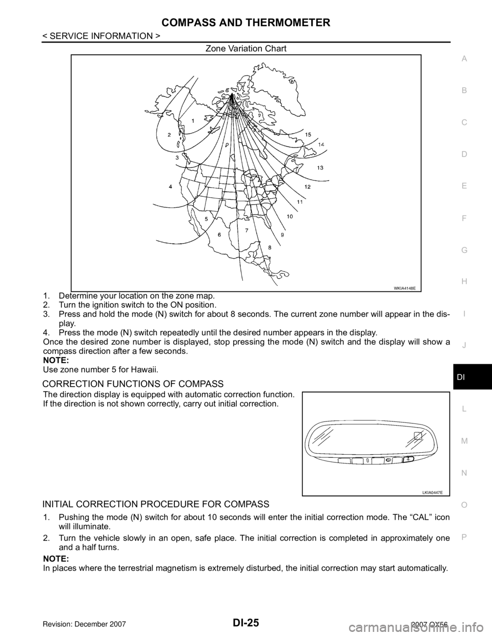
Zone Variation Chart
1. Determine your location on the zone map.
2. Turn the ignition switch to the ON position.
3. Press and hold the mode (N) switch for about 8 seconds. The current zone number will appear in the dis-
play.
4. Press the mode (N) switch repeatedly until the desired number appears in the display.
Once the desired zone number is displayed, stop pressing the mode (N) switch and the display will show a
compass direction after a few seconds.
NOTE:
Use zone number 5 for Hawaii.
CORRECTION FUNCTIONS OF COMPASS
The direction display is equipped with automatic correction function.
If the direction is not shown correctly, carry out initial correction.
INITIAL CORRECTION PROCEDURE FOR COMPASS
1. Pushing the mode (N) switch for about 10 seconds will enter the initial correction mode. The “CAL” icon
will illuminate.
2. Turn the vehicle slowly in an open, safe place. The initial correction is completed in approximately one
and a half turns.
NOTE:
In places where the terrestrial magnetism is extremely disturbed, the initial correction may start automatically.
WKIA4148E
LKIA0447E
Page 1076 of 3061
REAR VIEW MONITOR
DI-65
< SERVICE INFORMATION >
C
D
E
F
G
H
I
J
L
MA
B
DI
N
O
P
CONSULT-II START PROCEDURE
Refer to GI-36, "CONSULT-II Start Procedure".
WORK SUPPORT
Refer to DI-65, "Side Distance Guideline Correction" for details.
DATA MONITOR
Display Item List
Side Distance Guideline CorrectionINFOID:0000000003533545
This mode is used to modify the side distance guidelines if they are dislocated from the rear view monitor
image, because of variations of body/camera mounting conditions.
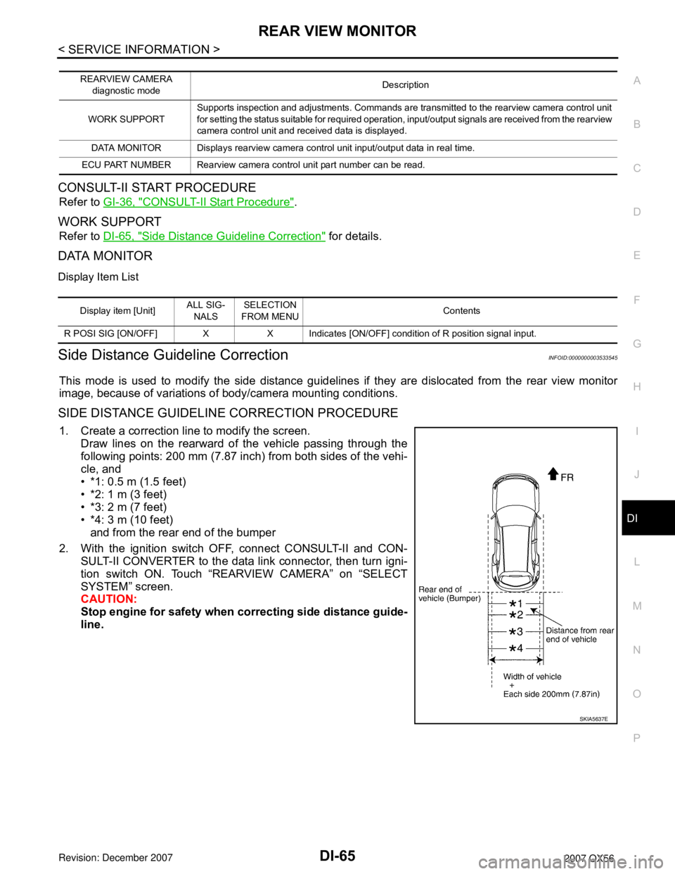
SIDE DISTANCE GUIDELINE CORRECTION PROCEDURE
1. Create a correction line to modify the screen.
Draw lines on the rearward of the vehicle passing through the
following points: 200 mm (7.87 inch) from both sides of the vehi-
cle, and
• *1: 0.5 m (1.5 feet)
• *2: 1 m (3 feet)
• *3: 2 m (7 feet)
• *4: 3 m (10 feet)
and from the rear end of the bumper
2. With the ignition switch OFF, connect CONSULT-II and CON-
SULT-II CONVERTER to the data link connector, then turn igni-
tion switch ON. Touch “REARVIEW CAMERA” on “SELECT
SYSTEM” screen.
CAUTION:
Stop engine for safety when correcting side distance guide-
line.
REARVIEW CAMERA
diagnostic modeDescription
WORK SUPPORTSupports inspection and adjustments. Commands are transmitted to the rearview camera control unit
for setting the status suitable for required operation, input/output signals are received from the rearview
camera control unit and received data is displayed.
DATA MONITOR Displays rearview camera control unit input/output data in real time.
ECU PART NUMBER Rearview camera control unit part number can be read.
Display item [Unit]ALL SIG-
NALSSELECTION
FROM MENUContents
R POSI SIG [ON/OFF] X X Indicates [ON/OFF] condition of R position signal input.
SKIA5637E
Page 1109 of 3061
EC-26
< SERVICE INFORMATION >
ENGINE CONTROL SYSTEM
The mixture ratio feedback system provides the best air-fuel mixture ratio for driveability and emission control.
The three way catalyst (manifold) can then better reduce CO, HC and NOx emissions. This system uses air
fuel ratio (A/F) sensor 1 in the exhaust manifold to monitor whether the engine operation is rich or lean. The
ECM adjusts the injection pulse width according to the sensor voltage signal. For more information about air
fuel ratio (A/F) sensor 1, refer to EC-225
. This maintains the mixture ratio within the range of stoichiometric
(ideal air-fuel mixture).
This stage is referred to as the closed loop control condition.
Heated oxygen sensor 2 is located downstream of the three way catalyst (manifold). Even if the switching
characteristics of air fuel ratio (A/F) sensor 1 shift, the air-fuel ratio is controlled to stoichiometric by the signal
from heated oxygen sensor 2.
Open Loop Control
The open loop system condition refers to when the ECM detects any of the following conditions. Feedback
control stops in order to maintain stabilized fuel combustion.
• Deceleration and acceleration
• High-load, high-speed operation
• Malfunction of A/F sensor 1 or its circuit
• Insufficient activation of A/F sensor 1 at low engine coolant temperature
• High engine coolant temperature
• During warm-up
• After shifting from N to D
• When starting the engine
MIXTURE RATIO SELF-LEARNING CONTROL
The mixture ratio feedback control system monitors the mixture ratio signal transmitted from A/F sensor 1.
This feedback signal is then sent to the ECM. The ECM controls the basic mixture ratio as close to the theoret-
ical mixture ratio as possible. However, the basic mixture ratio is not necessarily controlled as originally
designed. Both manufacturing differences (i.e., mass air flow sensor hot wire) and characteristic changes dur-
ing operation (i.e., injector clogging) directly affect mixture ratio.
Accordingly, the difference between the basic and theoretical mixture ratios is monitored in this system. This is
then computed in terms of “injection pulse duration” to automatically compensate for the difference between
the two ratios.
“Fuel trim” refers to the feedback compensation value compared against the basic injection duration. Fuel trim
includes short term fuel trim and long term fuel trim.
“Short term fuel trim” is the short-term fuel compensation used to maintain the mixture ratio at its theoretical
value. The signal from A/F sensor 1 indicates whether the mixture ratio is RICH or LEAN compared to the the-
oretical value. The signal then triggers a reduction in fuel volume if the mixture ratio is rich, and an increase in
fuel volume if it is lean.
“Long term fuel trim” is overall fuel compensation carried out long-term to compensate for continual deviation
of the short term fuel trim from the central value. Such deviation will occur due to individual engine differences,
wear over time and changes in the usage environment.
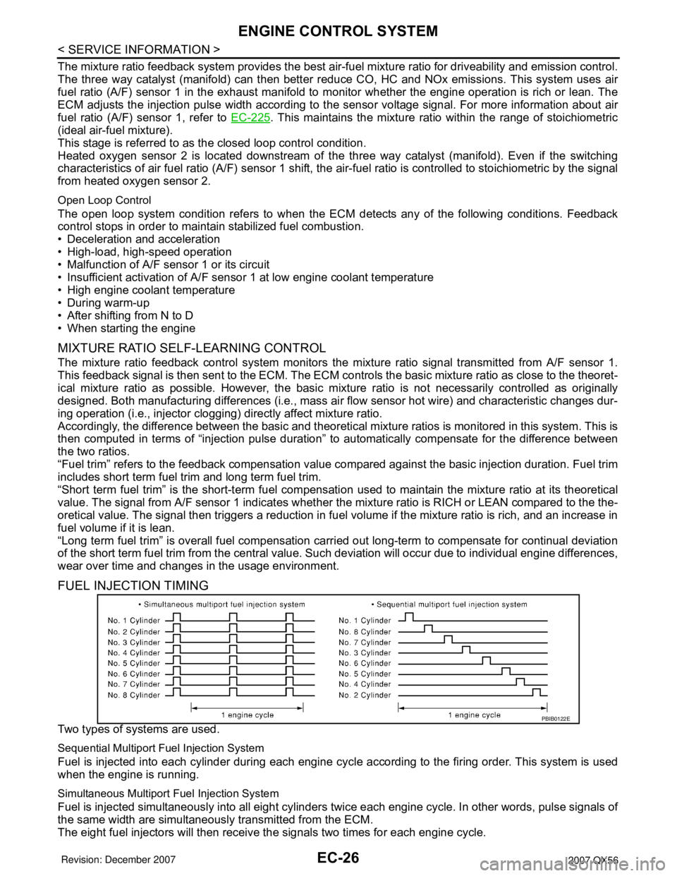
FUEL INJECTION TIMING
Two types of systems are used.
Sequential Multiport Fuel Injection System
Fuel is injected into each cylinder during each engine cycle according to the firing order. This system is used
when the engine is running.
Simultaneous Multiport Fuel Injection System
Fuel is injected simultaneously into all eight cylinders twice each engine cycle. In other words, pulse signals of
the same width are simultaneously transmitted from the ECM.
The eight fuel injectors will then receive the signals two times for each engine cycle.
PBIB0122E
Page 1146 of 3061
ON BOARD DIAGNOSTIC (OBD) SYSTEM
EC-63
< SERVICE INFORMATION >
C
D
E
F
G
H
I
J
K
L
MA
EC
N
P O
Actual work procedures are explained using a DTC as an example. Be careful so that not only the DTC, but all
of the data listed above, are cleared from the ECM memory during work procedures.
Malfunction Indicator Lamp (MIL)INFOID:0000000003531607
DESCRIPTION
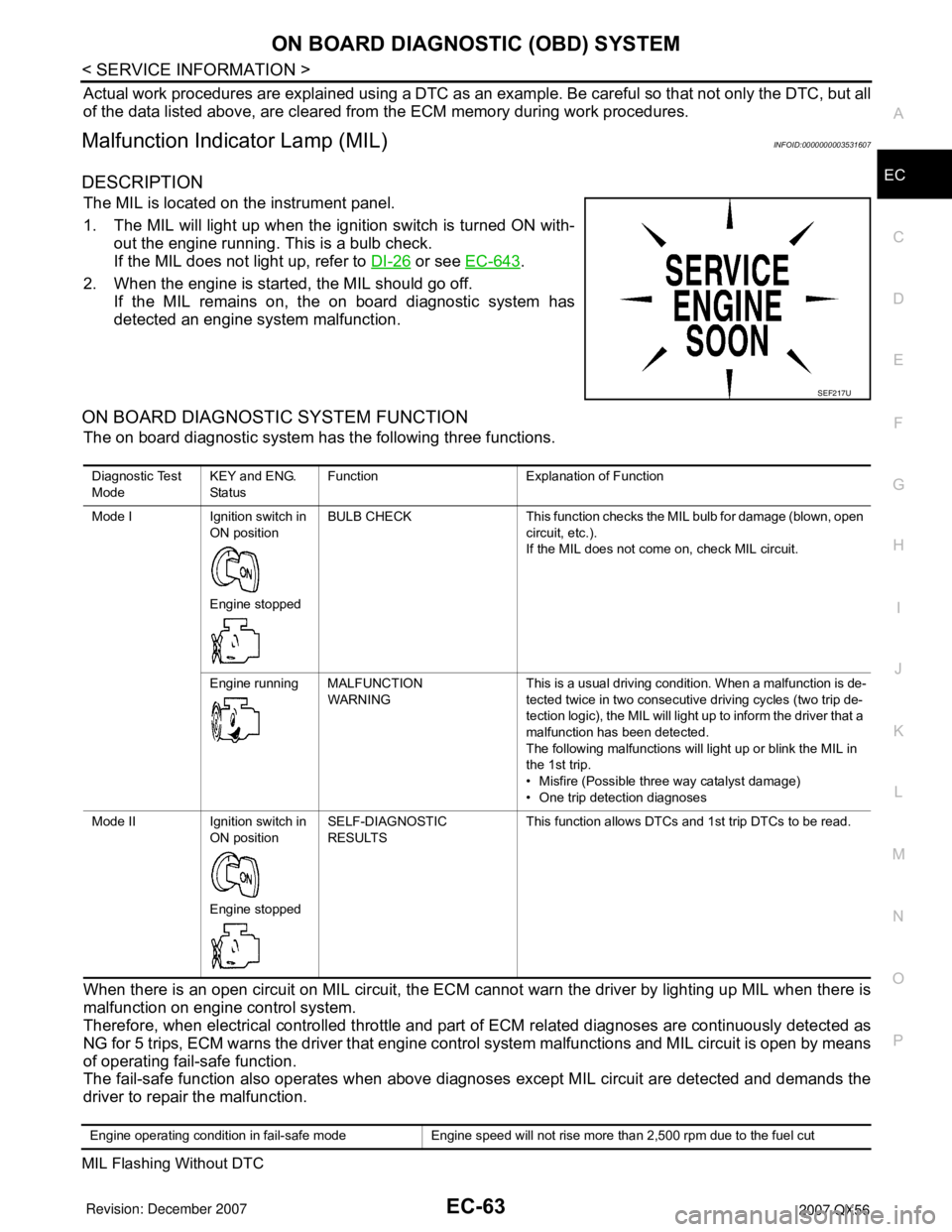
The MIL is located on the instrument panel.
1. The MIL will light up when the ignition switch is turned ON with-
out the engine running. This is a bulb check.
If the MIL does not light up, refer to DI-26
or see EC-643.
2. When the engine is started, the MIL should go off.
If the MIL remains on, the on board diagnostic system has
detected an engine system malfunction.
ON BOARD DIAGNOSTIC SYSTEM FUNCTION
The on board diagnostic system has the following three functions.
When there is an open circuit on MIL circuit, the ECM cannot warn the driver by lighting up MIL when there is
malfunction on engine control system.
Therefore, when electrical controlled throttle and part of ECM related diagnoses are continuously detected as
NG for 5 trips, ECM warns the driver that engine control system malfunctions and MIL circuit is open by means
of operating fail-safe function.
The fail-safe function also operates when above diagnoses except MIL circuit are detected and demands the
driver to repair the malfunction.
MIL Flashing Without DTC
SEF217U
Diagnostic Test
ModeKEY and ENG.
Sta tusFunction Explanation of Function
Mode I Ignition switch in
ON position
Engine stoppedBULB CHECK This function checks the MIL bulb for damage (blown, open
circuit, etc.).
If the MIL does not come on, check MIL circuit.
Engine running MALFUNCTION
WARNINGThis is a usual driving condition. When a malfunction is de-
tected twice in two consecutive driving cycles (two trip de-
tection logic), the MIL will light up to inform the driver that a
malfunction has been detected.
The following malfunctions will light up or blink the MIL in
the 1st trip.
• Misfire (Possible three way catalyst damage)
• One trip detection diagnoses
Mode II Ignition switch in
ON position
Engine stoppedSELF-DIAGNOSTIC
RESULTSThis function allows DTCs and 1st trip DTCs to be read.
Engine operating condition in fail-safe mode Engine speed will not rise more than 2,500 rpm due to the fuel cut
Page 1156 of 3061
BASIC SERVICE PROCEDURE
EC-73
< SERVICE INFORMATION >
C
D
E
F
G
H
I
J
K
L
MA
EC
N
P O
1. Start engine and warm it up to normal operating temperature.
2. Read idle speed in “DATA MONITOR” mode with CONSULT-II.
Refer to EC-75, "
Idle Speed and Ignition Timing Check" .
Without CONSULT-II
1. Start engine and warm it up to normal operating temperature.
2. Check idle speed.
Refer to EC-75, "
Idle Speed and Ignition Timing Check" .
OK or NG
OK >> GO TO 10.
NG >> GO TO 8.
8.DETECT MALFUNCTIONING PART
Check the following.
• Check camshaft position sensor (PHASE) and circuit. Refer to EC-342
.
• Check crankshaft position sensor (POS) and circuit. Refer to EC-336
.
OK or NG
OK >> GO TO 9.
NG >> 1. Repair or replace.
2. GO TO 4.
9.CHECK ECM FUNCTION
1. Substitute another known-good ECM to check ECM function. (ECM may be the cause of an incident, but
this is a rare case.)
2. Perform initialization of IVIS (NATS) system and registration of all IVIS (NATS) ignition key IDs. Refer to
BL-117, "
ECM Re-communicating Function".
>> GO TO 4.
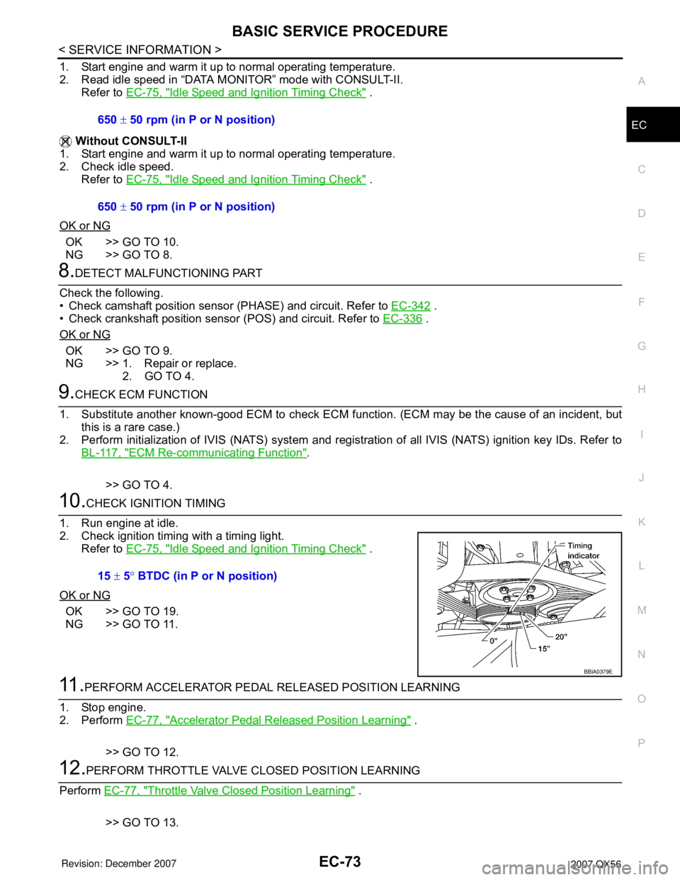
10.CHECK IGNITION TIMING
1. Run engine at idle.
2. Check ignition timing with a timing light.
Refer to EC-75, "
Idle Speed and Ignition Timing Check" .
OK or NG
OK >> GO TO 19.
NG >> GO TO 11.
11 .PERFORM ACCELERATOR PEDAL RELEASED POSITION LEARNING
1. Stop engine.
2. Perform EC-77, "
Accelerator Pedal Released Position Learning" .
>> GO TO 12.
12.PERFORM THROTTLE VALVE CLOSED POSITION LEARNING
Perform EC-77, "
Throttle Valve Closed Position Learning" .
>> GO TO 13. 650 ± 50 rpm (in P or N position)
650 ± 50 rpm (in P or N position)
15 ± 5° BTDC (in P or N position)
BBIA0379E
Page 1161 of 3061
EC-78
< SERVICE INFORMATION >
BASIC SERVICE PROCEDURE
3. Turn ignition switch OFF wait at least 10 seconds.
Make sure that throttle valve moves during above 10 seconds by confirming the operating sound.
Idle Air Volume LearningINFOID:0000000003531615
DESCRIPTION
Idle Air Volume Learning is an operation to learn the idle air volume that keeps each engine within the specific
range. It must be performed under any of the following conditions:
• Each time electric throttle control actuator or ECM is replaced.
• Idle speed or ignition timing is out of specification.
PREPARATION
Before performing Idle Air Volume Learning, make sure that all of the following conditions are satisfied.
Learning will be cancelled if any of the following conditions are missed for even a moment.
• Battery voltage: More than 12.9V (At idle)
• Engine coolant temperature: 70 - 100°C (158 - 212°F)
• Park/Neutral position (PNP) switch: ON
• Electric load switch: OFF
(Air conditioner, headlamp, rear window defogger)
On vehicles equipped with daytime light systems, if the parking brake is applied before the engine is
start the headlamp will not be illuminated.
• Steering wheel: Neutral (Straight-ahead position)
• Vehicle speed: Stopped
• Transmission: Warmed-up
- With CONSULT-II: Drive vehicle until “ATF TEMP SE 1” in “DATA MONITOR” mode of “A/T” system indi-
cates less than 0.9V.
- Without CONSULT-II: Drive vehicle for 10 minutes.
OPERATION PROCEDURE
With CONSULT-II
1. Perform EC-77, "Accelerator Pedal Released Position Learning" .
2. Perform EC-77, "
Throttle Valve Closed Position Learning" .
3. Start engine and warm it up to normal operating temperature.
4. Check that all items listed under the topic PREPARATION (previously mentioned) are in good order.
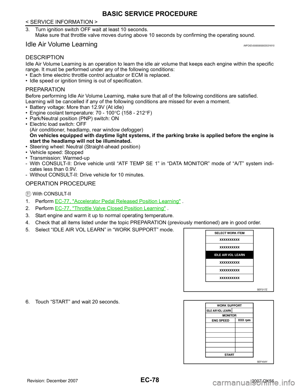
5. Select “IDLE AIR VOL LEARN” in “WORK SUPPORT” mode.
6. Touch “START” and wait 20 seconds.
SEF217Z
SEF454Y
Page 1162 of 3061
BASIC SERVICE PROCEDURE
EC-79
< SERVICE INFORMATION >
C
D
E
F
G
H
I
J
K
L
MA
EC
N
P O
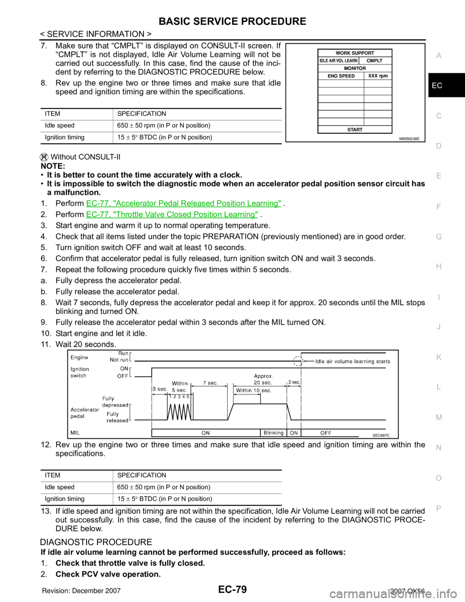
7. Make sure that “CMPLT” is displayed on CONSULT-II screen. If
“CMPLT” is not displayed, Idle Air Volume Learning will not be
carried out successfully. In this case, find the cause of the inci-
dent by referring to the DIAGNOSTIC PROCEDURE below.
8. Rev up the engine two or three times and make sure that idle
speed and ignition timing are within the specifications.
Without CONSULT-II
NOTE:
•It is better to count the time accurately with a clock.
•It is impossible to switch the diagnostic mode when an accelerator pedal position sensor circuit has
a malfunction.
1. Perform EC-77, "
Accelerator Pedal Released Position Learning" .
2. Perform EC-77, "
Throttle Valve Closed Position Learning" .
3. Start engine and warm it up to normal operating temperature.
4. Check that all items listed under the topic PREPARATION (previously mentioned) are in good order.
5. Turn ignition switch OFF and wait at least 10 seconds.
6. Confirm that accelerator pedal is fully released, turn ignition switch ON and wait 3 seconds.
7. Repeat the following procedure quickly five times within 5 seconds.
a. Fully depress the accelerator pedal.
b. Fully release the accelerator pedal.
8. Wait 7 seconds, fully depress the accelerator pedal and keep it for approx. 20 seconds until the MIL stops
blinking and turned ON.
9. Fully release the accelerator pedal within 3 seconds after the MIL turned ON.
10. Start engine and let it idle.
11. Wait 20 seconds.
12. Rev up the engine two or three times and make sure that idle speed and ignition timing are within the
specifications.
13. If idle speed and ignition timing are not within the specification, Idle Air Volume Learning will not be carried
out successfully. In this case, find the cause of the incident by referring to the DIAGNOSTIC PROCE-
DURE below.
DIAGNOSTIC PROCEDURE
If idle air volume learning cannot be performed successfully, proceed as follows:
1.Check that throttle valve is fully closed.
2.Check PCV valve operation.
ITEM SPECIFICATION
Idle speed 650 ± 50 rpm (in P or N position)
Ignition timing 15 ± 5° BTDC (in P or N position)
MBIB0238E
ITEM SPECIFICATION
Idle speed 650 ± 50 rpm (in P or N position)
Ignition timing 15 ± 5° BTDC (in P or N position)
SEC897C