2007 BMW MOTORRAD K 1200 GT Rider's Manual (in English)
-
 1
1 -
 2
2 -
 3
3 -
 4
4 -
 5
5 -
 6
6 -
 7
7 -
 8
8 -
 9
9 -
 10
10 -
 11
11 -
 12
12 -
 13
13 -
 14
14 -
 15
15 -
 16
16 -
 17
17 -
 18
18 -
 19
19 -
 20
20 -
 21
21 -
 22
22 -
 23
23 -
 24
24 -
 25
25 -
 26
26 -
 27
27 -
 28
28 -
 29
29 -
 30
30 -
 31
31 -
 32
32 -
 33
33 -
 34
34 -
 35
35 -
 36
36 -
 37
37 -
 38
38 -
 39
39 -
 40
40 -
 41
41 -
 42
42 -
 43
43 -
 44
44 -
 45
45 -
 46
46 -
 47
47 -
 48
48 -
 49
49 -
 50
50 -
 51
51 -
 52
52 -
 53
53 -
 54
54 -
 55
55 -
 56
56 -
 57
57 -
 58
58 -
 59
59 -
 60
60 -
 61
61 -
 62
62 -
 63
63 -
 64
64 -
 65
65 -
 66
66 -
 67
67 -
 68
68 -
 69
69 -
 70
70 -
 71
71 -
 72
72 -
 73
73 -
 74
74 -
 75
75 -
 76
76 -
 77
77 -
 78
78 -
 79
79 -
 80
80 -
 81
81 -
 82
82 -
 83
83 -
 84
84 -
 85
85 -
 86
86 -
 87
87 -
 88
88 -
 89
89 -
 90
90 -
 91
91 -
 92
92 -
 93
93 -
 94
94 -
 95
95 -
 96
96 -
 97
97 -
 98
98 -
 99
99 -
 100
100 -
 101
101 -
 102
102 -
 103
103 -
 104
104 -
 105
105 -
 106
106 -
 107
107 -
 108
108 -
 109
109 -
 110
110 -
 111
111 -
 112
112 -
 113
113 -
 114
114 -
 115
115 -
 116
116 -
 117
117 -
 118
118 -
 119
119 -
 120
120 -
 121
121 -
 122
122 -
 123
123 -
 124
124 -
 125
125 -
 126
126 -
 127
127 -
 128
128 -
 129
129 -
 130
130 -
 131
131 -
 132
132 -
 133
133 -
 134
134 -
 135
135 -
 136
136 -
 137
137 -
 138
138 -
 139
139 -
 140
140 -
 141
141 -
 142
142 -
 143
143 -
 144
144 -
 145
145 -
 146
146 -
 147
147 -
 148
148 -
 149
149 -
 150
150 -
 151
151 -
 152
152 -
 153
153 -
 154
154 -
 155
155 -
 156
156 -
 157
157 -
 158
158 -
 159
159 -
 160
160 -
 161
161 -
 162
162 -
 163
163 -
 164
164 -
 165
165 -
 166
166 -
 167
167 -
 168
168 -
 169
169 -
 170
170 -
 171
171 -
 172
172
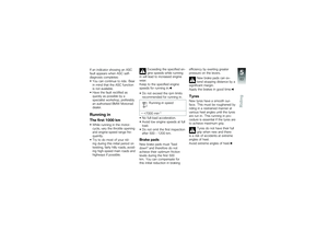
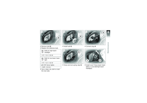
 Insert bulb3into the bulb
socket.
Turn the bulb socket clockwise
to install.
Parking light, left: connect
plug 2. Parking light, right: connect
plug
1.
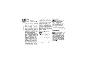
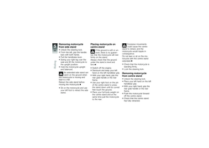
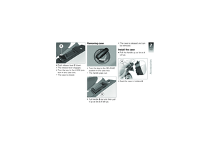
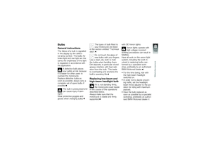
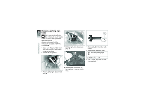
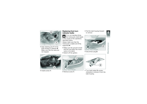
Replacing brake-light,
rear light and rear-
indi")
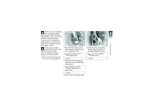
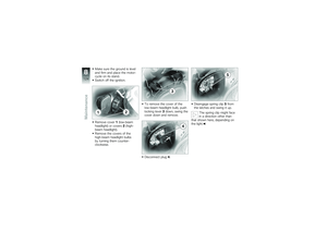
 Turn bulb socket2(brake-light
/rear-light bulb) or 3(indicat-
or bulb) counter-clockwise to
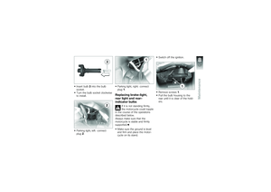
remove from the bulb housing. Press bulb
4into socket 5and
remove by turning it counter-
clockwise.
Replace")
 Seat retaining pins7of the
bulb housing in retainers 6.
Make sure that the wires are
not trapped.
Install screws 1.
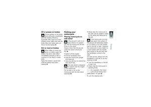
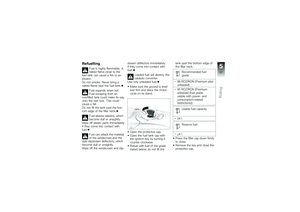
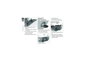
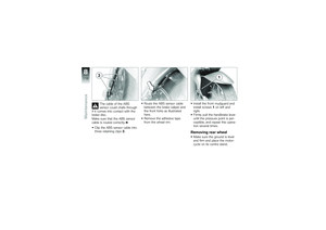
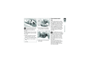
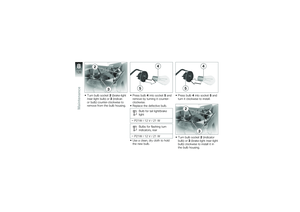
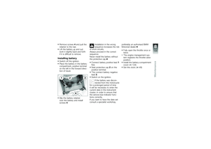
Replacing front turn
indicator bulbs
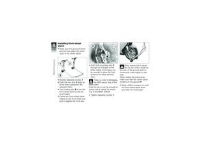
If it is not standing firmly,
the motorcycle co")
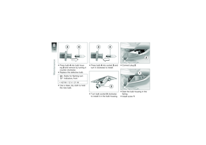
 Press bulb4into bulb hous-
ing 3and remove by turning it
counter-clockwise.
Replace the defective bulb.
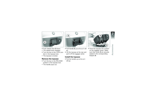
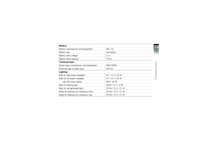
Bulbs for flashing turn
indicators, front
H21W / 12 V / 21 W
Use a clean, dry cloth to hold
the")
 Jump starting
The wires leading to the
power socket do not have
a load-capacity rating adequate
for jump-starting the engine. Ex-
cessively high current can lead
to a cable fire or damage to the
vehic")
 BatteryMaintenance instructionsCorrect upkeep, recharging and
storage will prolong the life of
the battery and are essential if
warranty claims are to be con-
sidered.
Compliance with the points be-
l")
 Only chargers suitable for
this mode of charging can
be used to recharge the battery
via the on-board socket. Unsuit-
able chargers could cause dam-
age to the motorcycles on-board
electrics.
Use BMW")
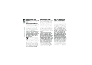
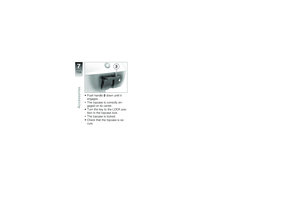
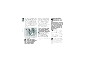
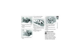
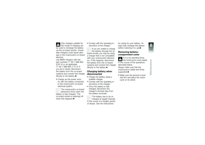
 Remove screws1.
Lift the battery compartment
cover up and back to remove.
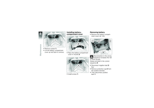
Installing battery-
compartment coverPlace the battery-compartment
cover in mounts 2
Install screws 1.
Removing batteryRemove")