Page 403 of 1226
Replacement
For removal and installation of spiral cable, refer to RS section
[``Installation Ð Air Bag Module and Spiral Cable'', ``SUPPLE-
MENTAL RESTRAINT SYSTEM (SRS)''].
+Each switch can be replaced without removing combination
switch base.
+To remove combination switch base, remove base attaching
screw.
+Before installing the steering wheel, align the steering wheel
guide pins with the screws which secure the combination switch
as shown in the left ®gure.
MEL304D
MEL326G
SEL151V
COMBINATION SWITCH
EL-58
Page 691 of 1226
CRANKSHAFT REAR OIL SEAL
1. Remove transmission assembly. (Refer to ``REMOVAL AND
INSTALLATION'' in MT section.)
2. Remove clutch cover assembly.
3. Remove ¯ywheel and rear plate.
4. Remove oil pan and oil pan gasket.
5. Remove oil seal retainer assembly.
6. Remove traces of liquid gasket using a scraper.
7. Remove rear oil seal from retainer.
8. Apply engine oil to new oil seal and install oil seal using a suit-
able tool.
9. Apply a continuous bead of liquid gasket to rear oil seal
retainer.
a. Coat of liquid gasket should be maintained within 2.0 to 3.0
mm (0.079 to 0.118 in) dia. range.
b. Attach oil seal retainer to cylinder block within ®ve min-
utes after coating.
c. Wait at least 30 minutes before re®lling engine oil or start-
ing engine.
d. Use Genuine Liquid Gasket or equivalent.
SEM896A
SEM895A
SEM897A
SLC822
SEM144B
OIL SEAL REPLACEMENT
EM-23
Page 694 of 1226
3. Measure runout of rotor shaft.
Runout (Total indicator reading):
0.056 - 0.127 mm (0.0022 - 0.0050 in)
4. Measure end play of rotor shaft.
End play:
0.013 - 0.097 mm (0.0005 - 0.0038 in)
TURBINE WHEEL
Check turbine wheel for the following:
+Oil
+Carbon deposits
+Deformed ®ns
+Contact with turbine housing
COMPRESSOR WHEEL
Check compressor wheel for the following:
+Oil
+Deformed ®ns
+Contact with compressor housing
WASTEGATE VALVE
Remove rod pin and check wastegate valve for cracks, deformation
and smooth movement.
Check valve seat surface for smoothness.
SEM800C
SEM801C
SEM802C
SEM803C
SEM804C
TURBOCHARGER
Inspection (Cont'd)
EM-26
Page 721 of 1226

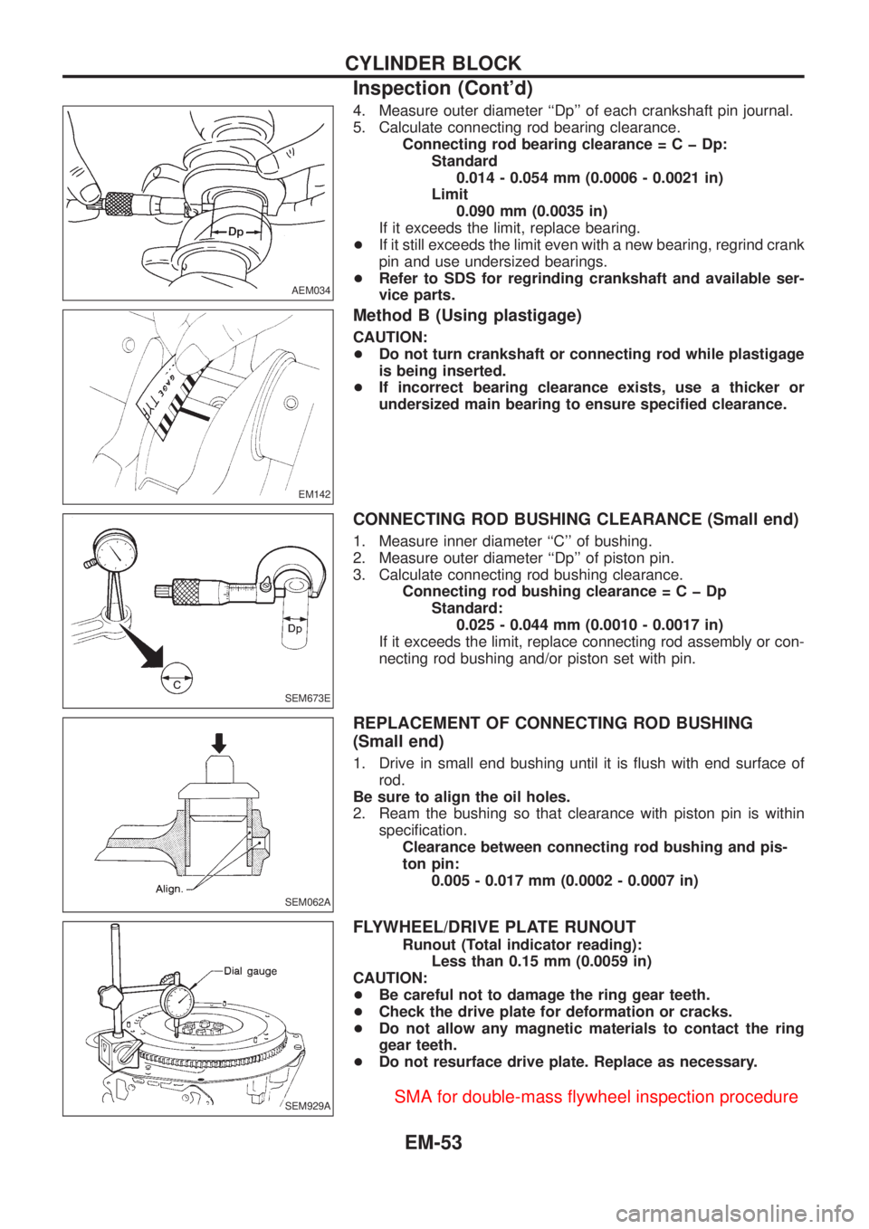
4. Measure outer diameter ``Dp'' of each crankshaft pin journal.
5. Calculate connecting rod bearing clearance.
Connecting rod bearing clearance=CþDp:
Standard
0.014 - 0.054 mm (0.0006 - 0.0021 in)
Limit
0.090 mm (0.0035 in)
If it exceeds the limit, replace bearing.
+If it still exceeds the limit even with a new bearing, regrind crank
pin and use undersized bearings.
+Refer to SDS for regrinding crankshaft and available ser-
vice parts.
Method B (Using plastigage)
CAUTION:
+Do not turn crankshaft or connecting rod while plastigage
is being inserted.
+If incorrect bearing clearance exists, use a thicker or
undersized main bearing to ensure speci®ed clearance.
CONNECTING ROD BUSHING CLEARANCE (Small end)
1. Measure inner diameter ``C'' of bushing.
2. Measure outer diameter ``Dp'' of piston pin.
3. Calculate connecting rod bushing clearance.
Connecting rod bushing clearance=CþDp
Standard:
0.025 - 0.044 mm (0.0010 - 0.0017 in)
If it exceeds the limit, replace connecting rod assembly or con-
necting rod bushing and/or piston set with pin.
REPLACEMENT OF CONNECTING ROD BUSHING
(Small end)
1. Drive in small end bushing until it is ¯ush with end surface of
rod.
Be sure to align the oil holes.
2. Ream the bushing so that clearance with piston pin is within
speci®cation.
Clearance between connecting rod bushing and pis-
ton pin:
0.005 - 0.017 mm (0.0002 - 0.0007 in)
FLYWHEEL/DRIVE PLATE RUNOUT
Runout (Total indicator reading):
Less than 0.15 mm (0.0059 in)
CAUTION:
+Be careful not to damage the ring gear teeth.
+Check the drive plate for deformation or cracks.
+Do not allow any magnetic materials to contact the ring
gear teeth.
+Do not resurface drive plate. Replace as necessary.
AEM034
EM142
SEM673E
SEM062A
SEM929A
CYLINDER BLOCK
Inspection (Cont'd)
EM-53
Page 732 of 1226
Undersize
Unit: mm (in)
Undersize Thickness ``T''Crank pin journal
diameter ``Dp''
0.08 (0.0031)1.536 - 1.540
(0.0605 - 0.0606)
Grind so that bearing
clearance is the
speci®ed value. 0.12 (0.0047)1.556 - 1.560
(0.0613 - 0.0614)
0.25 (0.0098)1.621 - 1.625
(0.0638 - 0.0640)
Bearing clearance
Unit: mm (in)
Main bearing clearance
Standard 0.036 - 0.063 (0.0014 - 0.0025)
Limit 0.12 (0.0047)
Connecting rod bearing clearance
Standard 0.031 - 0.055 (0.0012 - 0.0022)
Limit 0.11 (0.0043)
MISCELLANEOUS COMPONENTS
Unit: mm (in)
Camshaft sprocket runout limit
[TIR]0.1 (0.004)
Flywheel runout limit [TIR] 0.1 (0.004)
Drive plate runout limit [TIR] 0.1 (0.004)
SERVICE DATA AND SPECIFICATIONS (SDS)
Inspection and Adjustment (Cont'd)
EM-64
Page 733 of 1226

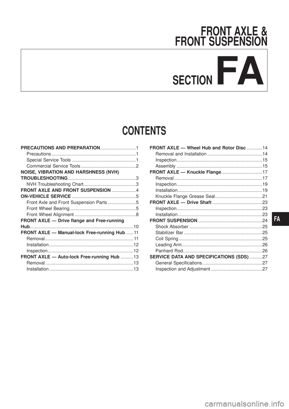
FRONT AXLE &
FRONT SUSPENSION
SECTION
FA
CONTENTS
PRECAUTIONS AND PREPARATION............................1
Precautions ..................................................................1
Special Service Tools ..................................................1
Commercial Service Tools ...........................................2
NOISE, VIBRATION AND HARSHNESS (NVH)
TROUBLESHOOTING.....................................................3
NVH Troubleshooting Chart.........................................3
FRONT AXLE AND FRONT SUSPENSION...................4
ON-VEHICLE SERVICE..................................................5
Front Axle and Front Suspension Parts ......................5
Front Wheel Bearing....................................................5
Front Wheel Alignment ................................................8
FRONT AXLE Ð Drive ¯ange and Free-running
Hub.................................................................................10
FRONT AXLE Ð Manual-lock Free-running Hub...... 11
Removal ..................................................................... 11
Installation ..................................................................12
Inspection...................................................................12
FRONT AXLE Ð Auto-lock Free-running Hub..........13
Removal .....................................................................13
Installation ..................................................................13FRONT AXLE Ð Wheel Hub and Rotor Disc............14
Removal and Installation ...........................................14
Inspection...................................................................15
Assembly ...................................................................15
FRONT AXLE Ð Knuckle Flange................................17
Removal .....................................................................17
Inspection...................................................................19
Installation ..................................................................19
Knuckle Flange Grease Seal.....................................21
FRONT AXLE Ð Drive Shaft.......................................23
Inspection...................................................................23
Installation ..................................................................23
FRONT SUSPENSION..................................................24
Shock Absorber .........................................................25
Stabilizer Bar .............................................................25
Coil Spring .................................................................25
Leading Arm...............................................................26
Panhard Rod..............................................................26
SERVICE DATA AND SPECIFICATIONS (SDS)..........27
General Speci®cations ...............................................27
Inspection and Adjustment ........................................27
FA
Page 734 of 1226
Precautions
+When installing rubber parts, ®nal tightening must be car-
ried out under unladen condition* with tires on ground.
* Fuel, radiator coolant and engine oil full. Spare tire, jack,
hand tools and mats in designated positions.
+Use ¯are nut wrench when removing and installing brake
tubes.
+After installing removed suspension parts, check wheel
alignment and adjust if necessary.
+Always torque brake lines when installing.
Special Service Tools
Tool number
Tool nameDescription
ST29020001
Gear arm puller
NT551
Removing tie-rod and drag link
a: 34 mm (1.34 in)
b: 6.5 mm (0.256 in)
c: 61.5 mm (2.421 in)
KV401021S0
Bearing race drift
NT153
Installing wheel bearing outer race
KV40105400
Wheel bearing
lock nut wrench
NT154
Removing and installing wheel bearing lock
nut
GG94310000
Flare nut torque wrench
NT406
Removing and installing brake piping
a: 10 mm (0.39 in)
SBR820BA
PRECAUTIONS AND PREPARATION
FA-1
Page 736 of 1226

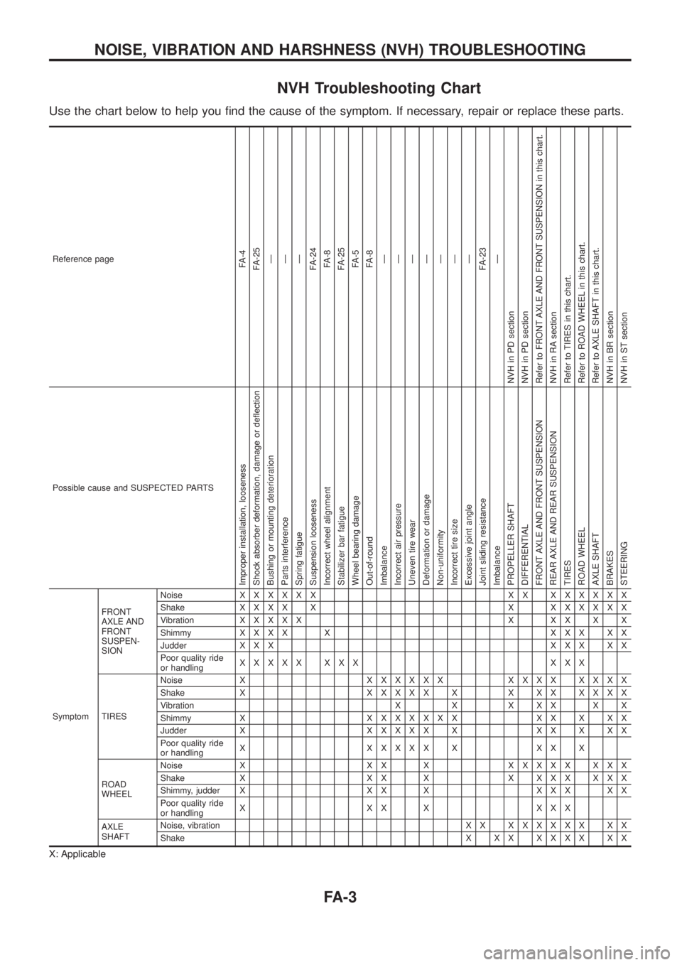
NVH Troubleshooting Chart
Use the chart below to help you ®nd the cause of the symptom. If necessary, repair or replace these parts.
Reference pageFA-4
FA-25
Ð
Ð
Ð
FA-24
FA-8
FA-25
FA-5
FA-8
Ð
Ð
Ð
Ð
Ð
Ð
Ð
FA-23
Ð
NVH in PD section
NVH in PD section
Refer to FRONT AXLE AND FRONT SUSPENSION in this chart.
NVH in RA section
Refer to TIRES in this chart.
Refer to ROAD WHEEL in this chart.
Refer to AXLE SHAFT in this chart.
NVH in BR section
NVH in ST section
Possible cause and SUSPECTED PARTS
Improper installation, looseness
Shock absorber deformation, damage or de¯ection
Bushing or mounting deterioration
Parts interference
Spring fatigue
Suspension looseness
Incorrect wheel alignment
Stabilizer bar fatigue
Wheel bearing damage
Out-of-round
Imbalance
Incorrect air pressure
Uneven tire wear
Deformation or damage
Non-uniformity
Incorrect tire size
Excessive joint angle
Joint sliding resistance
Imbalance
PROPELLER SHAFT
DIFFERENTIAL
FRONT AXLE AND FRONT SUSPENSION
REAR AXLE AND REAR SUSPENSION
TIRES
ROAD WHEEL
AXLE SHAFT
BRAKES
STEERING
SymptomFRONT
AXLE AND
FRONT
SUSPEN-
SIONNoiseXXXXXX XX XXXXXX
ShakeXXXX X X XXXXXX
VibrationXXXXX X XX X X
ShimmyXXXX X XXX XX
Judder X X XXXX XX
Poor quality ride
or handlingXXXXX XXX XXX
TIRESNoise XXXXXXX XXXX XXXX
Shake XXXXXX X X XX XXXX
Vibration X X X X X X X
Shimmy XXXXXXXX XX X XX
Judder XXXXXX X XX X XX
Poor quality ride
or handlingX XXXXX X XX X
ROAD
WHEELNoise X X X XXXXXX XXX
Shake X X X X X X X X X X X
Shimmy, judder X X X X X X X X X
Poor quality ride
or handlingX XX X XXX
AXLE
SHAFTNoise, vibration X XXXXXXX XX
ShakeX XX XXXX XX
X: Applicable
NOISE, VIBRATION AND HARSHNESS (NVH) TROUBLESHOOTING
FA-3