2006 NISSAN PATROL main
[x] Cancel search: mainPage 186 of 1226
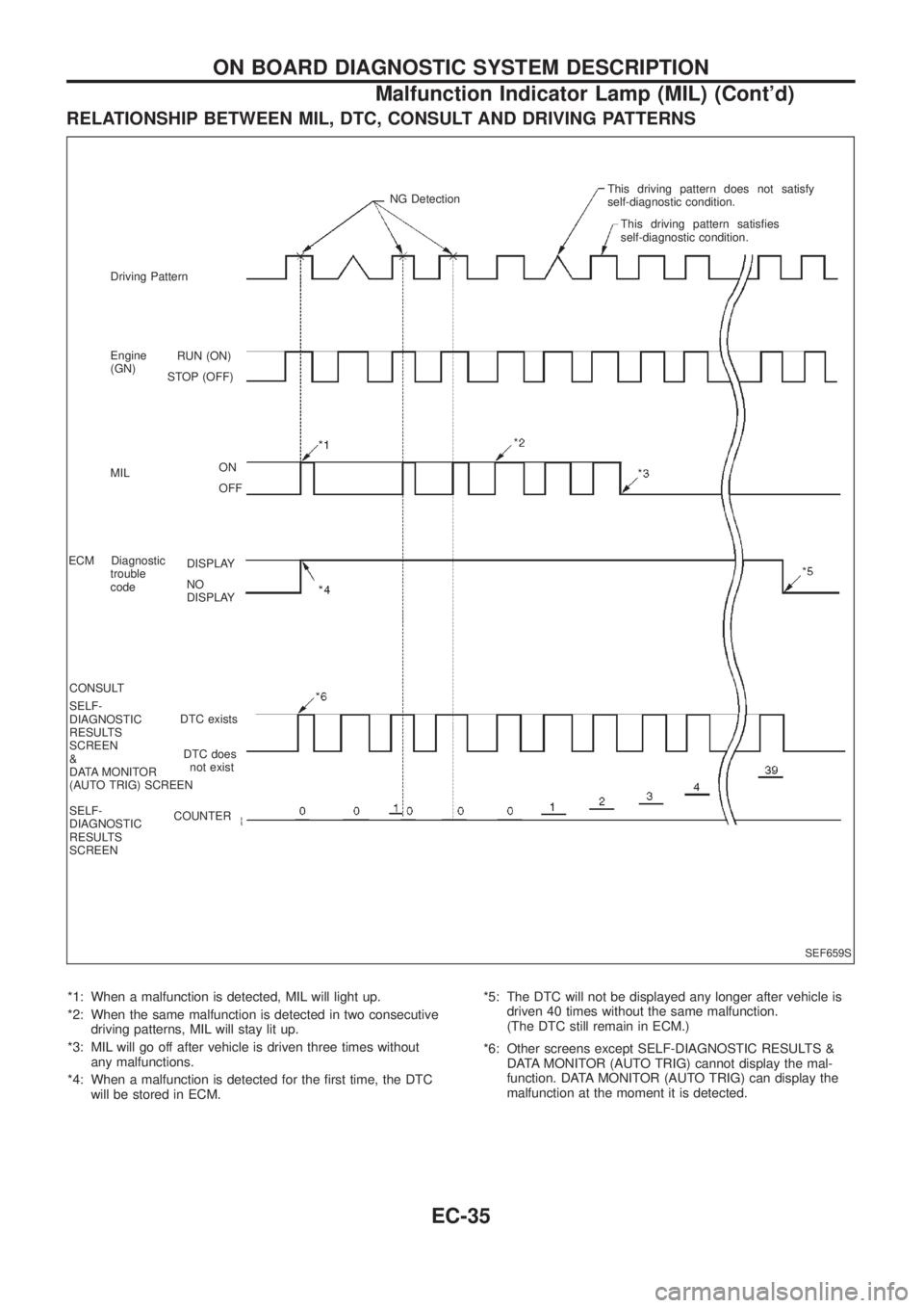
RELATIONSHIP BETWEEN MIL, DTC, CONSULT AND DRIVING PATTERNS
*1: When a malfunction is detected, MIL will light up.
*2: When the same malfunction is detected in two consecutive
driving patterns, MIL will stay lit up.
*3: MIL will go off after vehicle is driven three times without
any malfunctions.
*4: When a malfunction is detected for the ®rst time, the DTC
will be stored in ECM.*5: The DTC will not be displayed any longer after vehicle is
driven 40 times without the same malfunction.
(The DTC still remain in ECM.)
*6: Other screens except SELF-DIAGNOSTIC RESULTS &
DATA MONITOR (AUTO TRIG) cannot display the mal-
function. DATA MONITOR (AUTO TRIG) can display the
malfunction at the moment it is detected.
SEF659S
RUN (ON)
STOP (OFF)
ON
OFF
DISPLAY
NO
DISPLAY
DTC exists
DTC does
not exist
COUNTER Driving Pattern
Engine
(GN)
MIL
ECM Diagnostic
trouble
code
CONSULT
SELF-
DIAGNOSTIC
RESULTS
SCREEN
&
DATA MONITOR
(AUTO TRIG) SCREEN
SELF-
DIAGNOSTIC
RESULTS
SCREENNG DetectionThis driving pattern does not satisfy
self-diagnostic condition.
This driving pattern satis®es
self-diagnostic condition.
ON BOARD DIAGNOSTIC SYSTEM DESCRIPTION
Malfunction Indicator Lamp (MIL) (Cont'd)
EC-35
Page 189 of 1226
![NISSAN PATROL 2006 Service Manual SELF-DIAGNOSTIC MODE
Regarding items detected in ``SELF-DIAG RESULTS mode, refer to ``DIAGNOSTIC TROUBLE CODE
INDEX, EC-1.
DATA MONITOR MODE
Monitored item
[Unit]ECM
input
signalsMain
signalsDescr NISSAN PATROL 2006 Service Manual SELF-DIAGNOSTIC MODE
Regarding items detected in ``SELF-DIAG RESULTS mode, refer to ``DIAGNOSTIC TROUBLE CODE
INDEX, EC-1.
DATA MONITOR MODE
Monitored item
[Unit]ECM
input
signalsMain
signalsDescr](/manual-img/5/57368/w960_57368-188.png)
SELF-DIAGNOSTIC MODE
Regarding items detected in ``SELF-DIAG RESULTS'' mode, refer to ``DIAGNOSTIC TROUBLE CODE
INDEX'', EC-1.
DATA MONITOR MODE
Monitored item
[Unit]ECM
input
signalsMain
signalsDescription Remarks
CKPSzRPM
(TDC) [rpm]
jj
+The engine speed computed from the
crankshaft position sensor (TDC) signal
is displayed.
CKPSzRPM
(REF) [rpm]
jj
+The engine speed [determined by the
time between pulses from the crankshaft
position sensor (TDC) signal] is dis-
played.
CMPSzRPM -
PUMP [rpm]
jj
+The engine speed computed from the
camshaft position sensor (PUMP) signal
is displayed.
COOLAN TEMP/S
[ÉC] or [ÉF]
jj
+The engine coolant temperature (deter-
mined by the signal voltage of the engine
coolant temperature sensor) is displayed.+When the engine coolant temperature
sensor is open or short-circuited, ECM
enters fail-safe mode. The engine cool-
ant temperature determined by the ECM
is displayed.
VHCL SPEED SE
[km/h] or [mph]
jj+The vehicle speed computed from the
vehicle speed sensor signal is displayed.
FUEL TEMP SEN
[ÉC] or [ÉF]
jj
+The fuel temperature (determined by the
signal voltage of the fuel temperature
sensor) is displayed.
ACCEL POS SEN [V]
jj+The accelerator position sensor signal
voltage is displayed.
FULL ACCEL SW
[ON/OFF]
jj+Indicates [ON/OFF] condition from the
accelerator position switch signal.
ACCEL SW (FC)
[OPEN/CLOSE]
jj+Indicates [OPEN/CLOSE] condition from
the accelerator switch (FC) signal.
OFF ACCEL SW
[ON/OFF]
jj+Indicates [ON/OFF] condition from the
accelerator position switch signal.
C/SLEEV POS/S [V]
jj+The control sleeve position sensor signal
voltage is displayed.
BATTERY VOLT [V]
jj+The power supply voltage of ECM is dis-
played.
P/N POSI SW
[ON/OFF]
jj+Indicates [ON/OFF] condition from the
park/neutral position switch signal.
START SIGNAL
[ON/OFF]
jj+Indicates [ON/OFF] condition from the
starter signal.+After starting the engine, [OFF] is dis-
played regardless of the starter signal.
NOTE:
Any monitored item that does not match the vehicle being diagnosed is deleted from the display automatically.
ON BOARD DIAGNOSTIC SYSTEM DESCRIPTION
CONSULT (Cont'd)
EC-38
Page 190 of 1226
![NISSAN PATROL 2006 Service Manual Monitored item
[Unit]ECM
input
signalsMain
signalsDescription Remarks
AIR COND SIG
[ON/OFF]
jj
+Indicates [ON/OFF] condition of the air
conditioner switch as determined by the
air conditioner signal.
NISSAN PATROL 2006 Service Manual Monitored item
[Unit]ECM
input
signalsMain
signalsDescription Remarks
AIR COND SIG
[ON/OFF]
jj
+Indicates [ON/OFF] condition of the air
conditioner switch as determined by the
air conditioner signal.](/manual-img/5/57368/w960_57368-189.png)
Monitored item
[Unit]ECM
input
signalsMain
signalsDescription Remarks
AIR COND SIG
[ON/OFF]
jj
+Indicates [ON/OFF] condition of the air
conditioner switch as determined by the
air conditioner signal.
IGN SW
[ON/OFF]
jj+Indicates [ON/OFF] condition from igni-
tion switch signal.
MAS AIR/FL SE [V]
jj+The signal voltage of the mass air ¯ow
sensor is displayed.+When the engine is stopped, a certain
value is indicated.
ACT INJ TIMG [É]
jj
+The actual injection timing angle deter-
mined by the ECM (an approximate
average angle between injection start
and end from TDC) is displayed.
INJ TIMG C/V [%]+Indicates the duty ratio of fuel injection
timing control valve.
DECELER F/CUT
[ON/OFF]
j
+Indicates [ON/OFF] condition from decel-
eration fuel cut signal.+When the accelerator pedal is released
quickly with engine speed at 3,000 rpm
or more, ``ON'' is displayed.
FUEL CUT S/V
[ON/OFF]
j
+The control condition of the fuel cut sole-
noid valve (determined by ECM accord-
ing to the input signal) is indicted.
+OFF ... Fuel cut solenoid valve is not
operating.
ON ... Fuel cut solenoid valve is operat-
ing.+When the fuel cut solenoid valve is not
operating, fuel is not supplied to injection
nozzles.
GLOW RLY [ON/OFF]
j
+The glow relay control condition (deter-
mined by ECM according to the input
signal) is displayed.
COOLING FAN
[LOW/HI/OFF]
j
+Indicates the control condition of the
cooling fans (determined by ECM
according to the input signal).
+LOW ... Operates at low speed.
HI ... Operates at high speed.
OFF ... Stopped.
I/C FAN RLY
[ON/OFF]
j
+Indicates the control condition of the
charge air cooler fan (determined by
ECM according to the input signals).
EGRC SOL/V A
[ON/OFF]+The control condition of the EGRC-sole-
noid valve A (determined by ECM
according to the input signal) is indi-
cated.
+OFF ... EGRC-solenoid valve A is not
operating.
ON ... EGRC-solenoid valve A is operat-
ing.
EGRC SOL/V B
[ON/OFF]+The control condition of the EGRC-sole-
noid valve B (determined by ECM
according to the input signal) is indi-
cated.
+OFF ... EGRC-solenoid valve B is not
operating.
ON ... EGRC-solenoid valve B is operat-
ing.
THROT RLY
[ON/OFF]+The control condition of the throttle con-
trol solenoid valve (determined by ECM
according to the input signal) is indi-
cated.
+OFF ... Throttle control solenoid valve is
not operating.
ON ... Throttle control solenoid valve is
operating.
ON BOARD DIAGNOSTIC SYSTEM DESCRIPTION
CONSULT (Cont'd)
EC-39
Page 195 of 1226
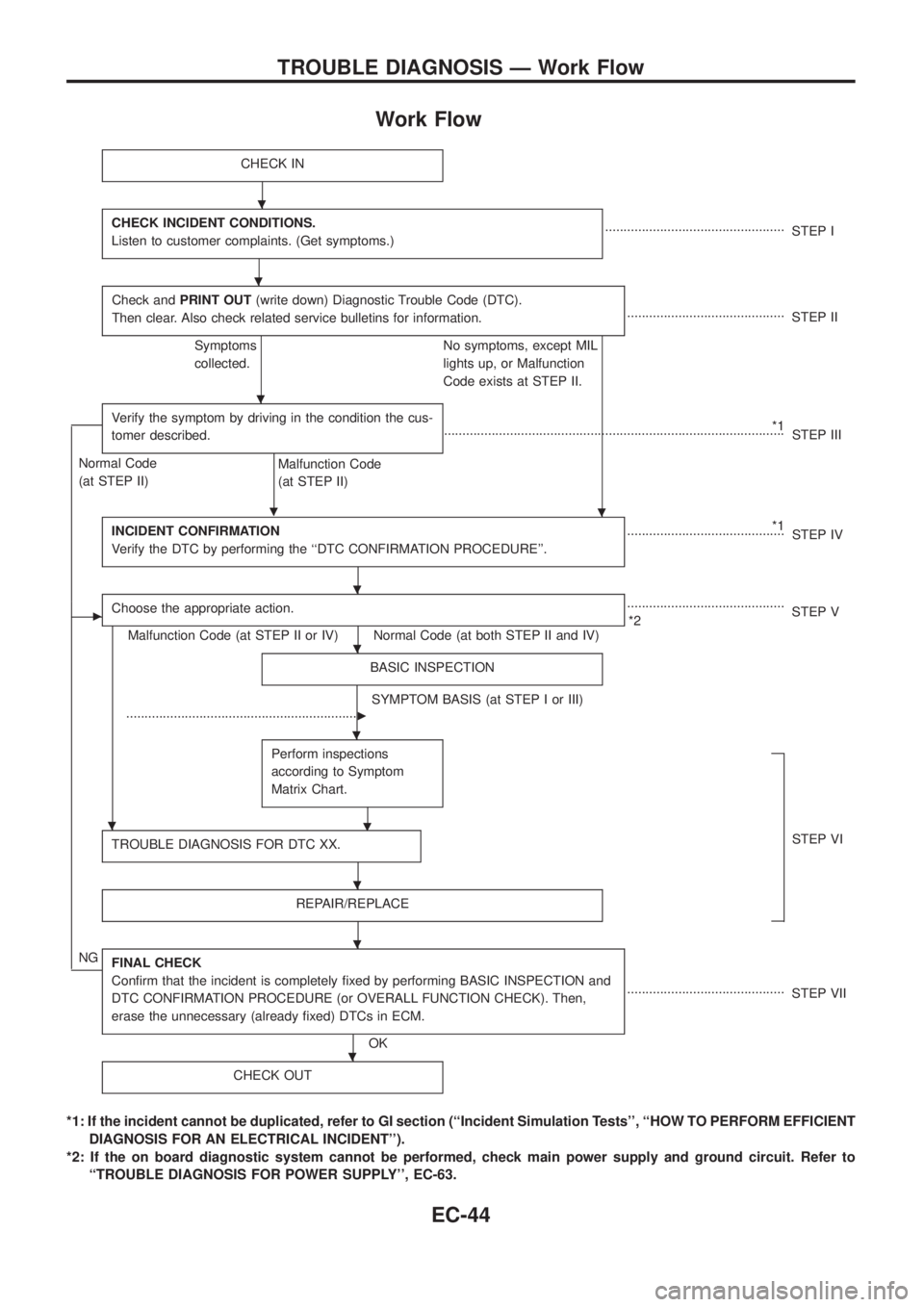
Work Flow
CHECK IN
CHECK INCIDENT CONDITIONS.
Listen to customer complaints. (Get symptoms.).................................................
STEP I
Check andPRINT OUT(write down) Diagnostic Trouble Code (DTC).
Then clear. Also check related service bulletins for information.
...........................................
STEP II
Symptoms
collected.No symptoms, except MIL
lights up, or Malfunction
Code exists at STEP II.
Verify the symptom by driving in the condition the cus-
tomer described.
.
*1
.............................................................................................
STEP III
Normal Code
(at STEP II)
Malfunction Code
(at STEP II)
INCIDENT CONFIRMATION
Verify the DTC by performing the ``DTC CONFIRMATION PROCEDURE''.
*1
...........................................
STEP IV
cChoose the appropriate action.
Malfunction Code (at STEP II or IV) Normal Code (at both STEP II and IV)...........................................
*2STEP V
BASIC INSPECTION
SYMPTOM BASIS (at STEP I or III)
................................................................
c
Perform inspections
according to Symptom
Matrix Chart.
.
TROUBLE DIAGNOSIS FOR DTC XX.STEP VI
REPAIR/REPLACE
NGFINAL CHECK
Con®rm that the incident is completely ®xed by performing BASIC INSPECTION and
DTC CONFIRMATION PROCEDURE (or OVERALL FUNCTION CHECK). Then,
erase the unnecessary (already ®xed) DTCs in ECM.
OK...........................................
STEP VII
CHECK OUT
*1: If the incident cannot be duplicated, refer to GI section (``Incident Simulation Tests'', ``HOW TO PERFORM EFFICIENT
DIAGNOSIS FOR AN ELECTRICAL INCIDENT'').
*2: If the on board diagnostic system cannot be performed, check main power supply and ground circuit. Refer to
``TROUBLE DIAGNOSIS FOR POWER SUPPLY'', EC-63.
.
.
.
.
.
.
.
.
.
.
.
TROUBLE DIAGNOSIS Ð Work Flow
EC-44
Page 197 of 1226
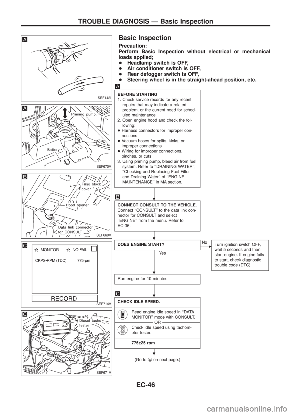
Basic Inspection
Precaution:
Perform Basic Inspection without electrical or mechanical
loads applied;
+Headlamp switch is OFF,
+Air conditioner switch is OFF,
+Rear defogger switch is OFF,
+Steering wheel is in the straight-ahead position, etc.
BEFORE STARTING
1. Check service records for any recent
repairs that may indicate a related
problem, or the current need for sched-
uled maintenance.
2. Open engine hood and check the fol-
lowing:
+Harness connectors for improper con-
nections
+Vacuum hoses for splits, kinks, or
improper connections
+Wiring for improper connections,
pinches, or cuts
3. Using priming pump, bleed air from fuel
system. Refer to ``DRAINING WATER'',
``Checking and Replacing Fuel Filter
and Draining Water'' of ``ENGINE
MAINTENANCE'' in MA section.
CONNECT CONSULT TO THE VEHICLE.
Connect ``CONSULT'' to the data link con-
nector for CONSULT and select
``ENGINE'' from the menu. Refer to
EC-36.
DOES ENGINE START?
Ye s
cNo
Turn ignition switch OFF,
wait 5 seconds and then
start engine. If engine fails
to start, check diagnostic
trouble code (DTC).
Run engine for 10 minutes.
CHECK IDLE SPEED.
----------------------------------------------------------------------------------------------------------------------------------------------------------------------------------------------------------------------------------------------------------------------------------------------------------------
Read engine idle speed in ``DATA
MONITOR'' mode with CONSULT.
--------------------------------------------------------------------------------------------------------------------------------------OR--------------------------------------------------------------------------------------------------------------------------------------
Check idle speed using tachom-
eter tester.
----------------------------------------------------------------------------------------------------------------------------------------------------------------------------------------------------------------------------------------------------------------------------------------------------------------
775 25 rpm
(Go tojAon next page.)
SEF142I
SEF670V
SEF669V
SEF714V
SEF671V
.
.
.
.
.
TROUBLE DIAGNOSIS Ð Basic Inspection
EC-46
Page 198 of 1226
jA
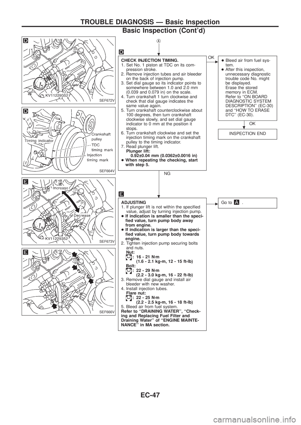
CHECK INJECTION TIMING.
1. Set No. 1 piston at TDC on its com-
pression stroke.
2. Remove injection tubes and air bleeder
on the back of injection pump.
3. Set dial gauge so its indicator points to
somewhere between 1.0 and 2.0 mm
(0.039 and 0.079 in) on the scale.
4. Turn crankshaft 1 turn clockwise and
check that dial gauge indicates the
same value again.
5. Turn crankshaft counterclockwise about
100 degrees, then turn crankshaft
clockwise slowly, and set dial gauge
indicator to 0 mm at the position it
stops.
6. Turn crankshaft clockwise and set the
injection timing mark on the crankshaft
pulley to the timing indicator.
7. Read plunger lift.
Plunger lift:
0.92 0.04 mm (0.0362 0.0016 in)
+When repeating the checking, start
with step 5.
NG
cOK
+Bleed air from fuel sys-
tem.
+After this inspection,
unnecessary diagnostic
trouble code No. might
be displayed.
Erase the stored
memory in ECM.
Refer to ``ON BOARD
DIAGNOSTIC SYSTEM
DESCRIPTION'' (EC-30)
and ``HOW TO ERASE
DTC'' (EC-30).
OK
INSPECTION END
ADJUSTING
1. If plunger lift is not within the speci®ed
value, adjust by turning injection pump.
+If indication is smaller than the speci-
®ed value, turn pump body away
from engine.
+If indication is larger than the speci-
®ed value, turn pump body towards
engine.
2. Tighten injection pump securing bolts
and nuts.
Nut:
: 16-21Nzm
(1.6 - 2.1 kg-m, 12 - 15 ft-lb)
Bolt:
: 22-29Nzm
(2.2 - 3.0 kg-m, 16 - 22 ft-lb)
3. Remove dial gauge and install air
bleeder with new washer.
4. Install injection tubes.
Flare nut:
: 22-25Nzm
(2.2 - 2.5 kg-m, 16 - 18 ft-lb)
5. Bleed air from fuel system.
Refer to ``DRAINING WATER'', ``Check-
ing and Replacing Fuel Filter and
Draining Water'' of ``ENGINE MAINTE-
NANCE'' in MA section.
cGo to.
SEF672V
SEF664V
SEF673V
SEF666V
.
.
.
TROUBLE DIAGNOSIS Ð Basic Inspection
Basic Inspection (Cont'd)
EC-47
Page 199 of 1226
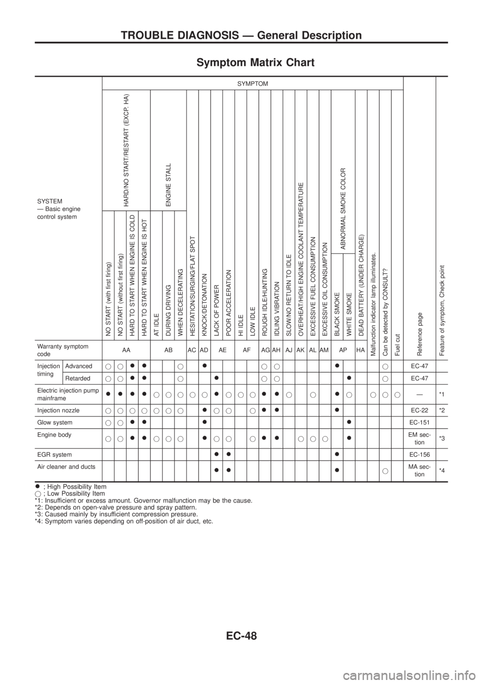
Symptom Matrix Chart
SYSTEM
Ð Basic engine
control systemSYMPTOM
Reference page
Feature of symptom, Check pointHARD/NO START/RESTART (EXCP. HA)
ENGINE STALL
HESITATION/SURGING/FLAT SPOT
KNOCK/DETONATION
LACK OF POWER
POOR ACCELERATION
HI IDLE
LOW IDLE
ROUGH IDLE/HUNTING
IDLING VIBRATION
SLOW/NO RETURN TO IDLE
OVERHEAT/HIGH ENGINE COOLANT TEMPERATURE
EXCESSIVE FUEL CONSUMPTION
EXCESSIVE OIL CONSUMPTION
ABNORMAL SMOKE COLOR
DEAD BATTERY (UNDER CHARGE)
Malfunction indicator lamp illuminates.
Can be detected by CONSULT?
Fuel cutNO START (with ®rst ®ring)
NO START (without ®rst ®ring)
HARD TO START WHEN ENGINE IS COLD
HARD TO START WHEN ENGINE IS HOT
AT IDLE
DURING DRIVING
WHEN DECELERATING
BLACK SMOKE
WHITE SMOKEWarranty symptom
codeAA AB AC AD AE AF AG AH AJ AK AL AM AP HA
Injection
timingAdvancedjj
++j+jj+jEC-47
Retardedjj
++j+jj+jEC-47
Electric injection pump
mainframe
++++jjjjj+jjj++jj+j jjjÐ*1
Injection nozzlejjjjjjj
+jj j++ +EC-22 *2
Glow systemjj
++ + +EC-151
Engine body
jj
++jjj+jj j++jjj+EM sec-
tion*3
EGR system
++ +EC-156
Air cleaner and ducts
++ +jMA sec-
tion*4
+; High Possibility Item
j; Low Possibility Item
*1: Insufficient or excess amount. Governor malfunction may be the cause.
*2: Depends on open-valve pressure and spray pattern.
*3: Caused mainly by insufficient compression pressure.
*4: Symptom varies depending on off-position of air duct, etc.
TROUBLE DIAGNOSIS Ð General Description
EC-48
Page 214 of 1226
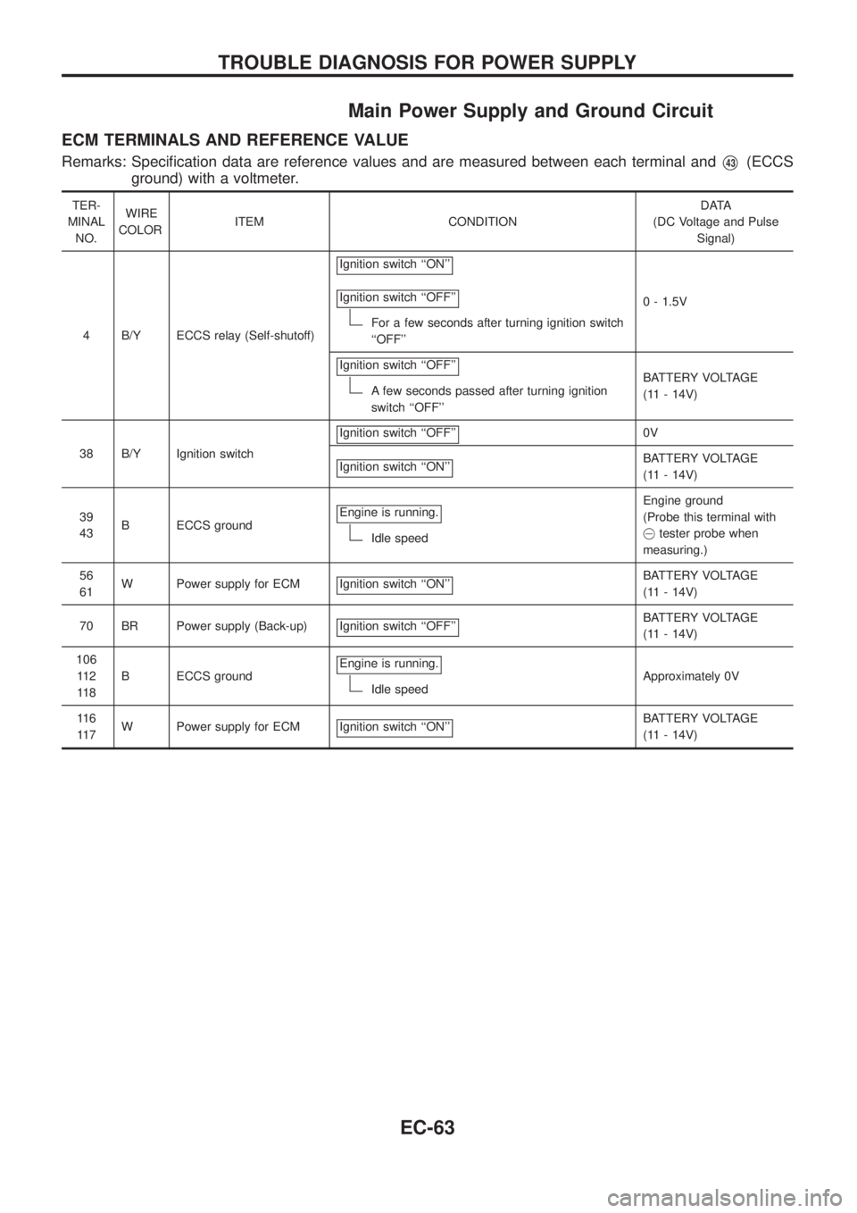
Main Power Supply and Ground Circuit
ECM TERMINALS AND REFERENCE VALUE
Remarks: Speci®cation data are reference values and are measured between each terminal andV43(ECCS
ground) with a voltmeter.
TER-
MINAL
NO.WIRE
COLORITEM CONDITIONDATA
(DC Voltage and Pulse
Signal)
4 B/Y ECCS relay (Self-shutoff)Ignition switch ``ON''
Ignition switch ``OFF''
For a few seconds after turning ignition switch
``OFF''0 - 1.5V
Ignition switch ``OFF''
A few seconds passed after turning ignition
switch ``OFF''BATTERY VOLTAGE
(11 - 14V)
38 B/Y Ignition switchIgnition switch ``OFF''
0V
Ignition switch ``ON''
BATTERY VOLTAGE
(11 - 14V)
39
43B ECCS groundEngine is running.
Idle speedEngine ground
(Probe this terminal with
@tester probe when
measuring.)
56
61W Power supply for ECM Ignition switch ``ON''
BATTERY VOLTAGE
(11 - 14V)
70 BR Power supply (Back-up) Ignition switch ``OFF''
BATTERY VOLTAGE
(11 - 14V)
106
11 2
11 8B ECCS groundEngine is running.
Idle speedApproximately 0V
11 6
11 7W Power supply for ECM Ignition switch ``ON''
BATTERY VOLTAGE
(11 - 14V)
TROUBLE DIAGNOSIS FOR POWER SUPPLY
EC-63