2006 NISSAN PATROL main
[x] Cancel search: mainPage 463 of 1226
Trouble Diagnoses
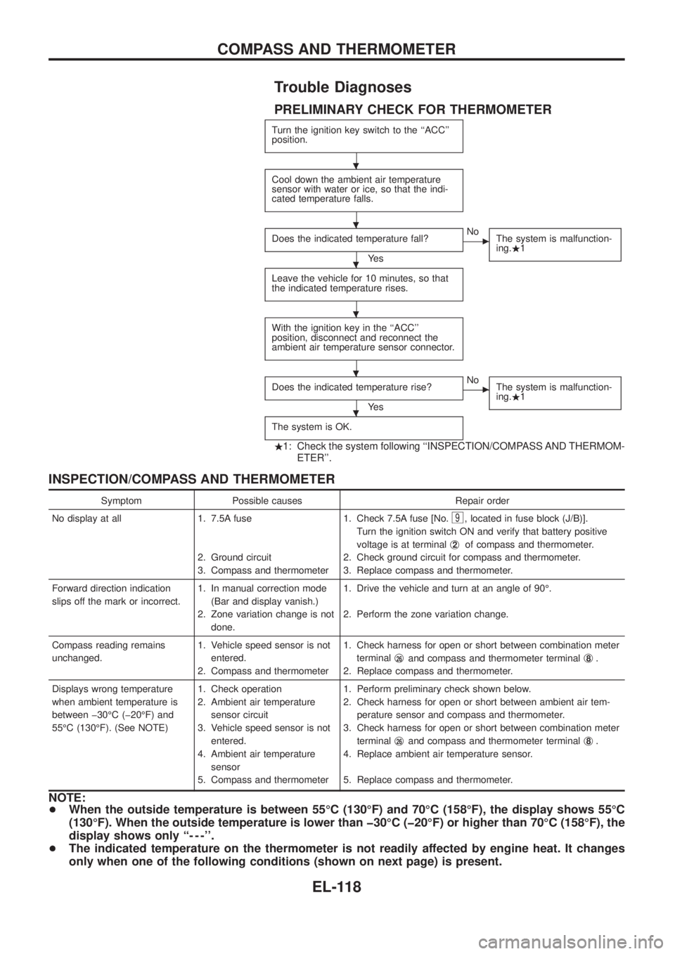
PRELIMINARY CHECK FOR THERMOMETER
Turn the ignition key switch to the ``ACC''
position.
Cool down the ambient air temperature
sensor with water or ice, so that the indi-
cated temperature falls.
Does the indicated temperature fall?
Ye s
cNo
The system is malfunction-
ing..1
Leave the vehicle for 10 minutes, so that
the indicated temperature rises.
With the ignition key in the ``ACC''
position, disconnect and reconnect the
ambient air temperature sensor connector.
Does the indicated temperature rise?
Ye s
cNo
The system is malfunction-
ing..1
The system is OK.
.1: Check the system following ``INSPECTION/COMPASS AND THERMOM-
ETER''.
INSPECTION/COMPASS AND THERMOMETER
Symptom Possible causes Repair order
No display at all 1. 7.5A fuse
2. Ground circuit
3. Compass and thermometer1. Check 7.5A fuse [No.
9, located in fuse block (J/B)].
Turn the ignition switch ON and verify that battery positive
voltage is at terminalj
2of compass and thermometer.
2. Check ground circuit for compass and thermometer.
3. Replace compass and thermometer.
Forward direction indication
slips off the mark or incorrect.1. In manual correction mode
(Bar and display vanish.)
2. Zone variation change is not
done.1. Drive the vehicle and turn at an angle of 90É.
2. Perform the zone variation change.
Compass reading remains
unchanged.1. Vehicle speed sensor is not
entered.
2. Compass and thermometer1. Check harness for open or short between combination meter
terminalj
26and compass and thermometer terminalj8.
2. Replace compass and thermometer.
Displays wrong temperature
when ambient temperature is
between þ30ÉC (þ20ÉF) and
55ÉC (130ÉF). (See NOTE)1. Check operation
2. Ambient air temperature
sensor circuit
3. Vehicle speed sensor is not
entered.
4. Ambient air temperature
sensor
5. Compass and thermometer1. Perform preliminary check shown below.
2. Check harness for open or short between ambient air tem-
perature sensor and compass and thermometer.
3. Check harness for open or short between combination meter
terminalj
26and compass and thermometer terminalj8.
4. Replace ambient air temperature sensor.
5. Replace compass and thermometer.
NOTE:
+When the outside temperature is between 55ÉC (130ÉF) and 70ÉC (158ÉF), the display shows 55ÉC
(130ÉF). When the outside temperature is lower than þ30ÉC (þ20ÉF) or higher than 70ÉC (158ÉF), the
display shows only ``- - -''.
+The indicated temperature on the thermometer is not readily affected by engine heat. It changes
only when one of the following conditions (shown on next page) is present.
.
.
.
.
.
.
COMPASS AND THERMOMETER
EL-118
Page 517 of 1226
Trouble Diagnoses
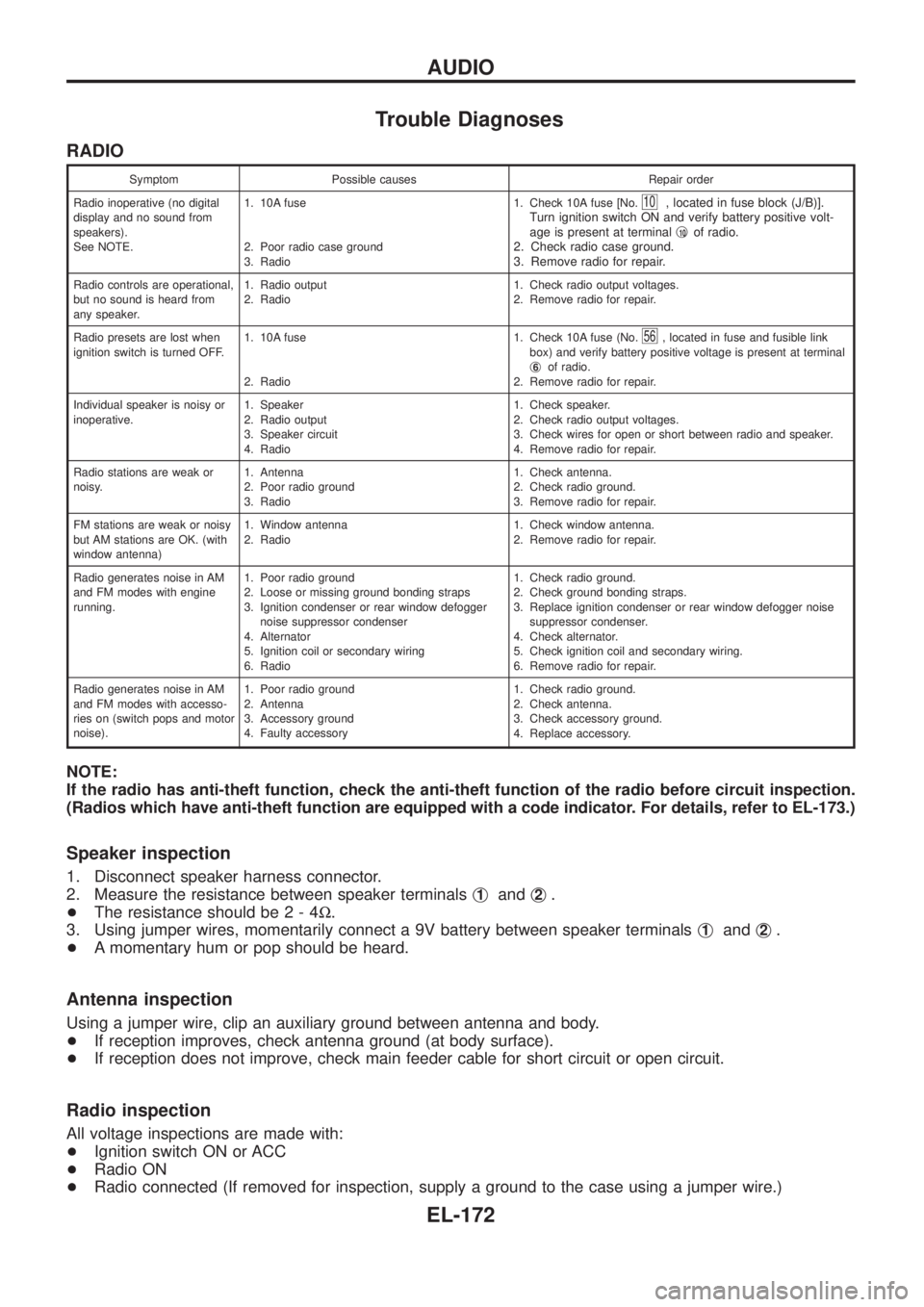
RADIO
Symptom Possible causes Repair order
Radio inoperative (no digital
display and no sound from
speakers).
See NOTE.1. 10A fuse
2. Poor radio case ground
3. Radio1. Check 10A fuse [No.
10, located in fuse block (J/B)].
Turn ignition switch ON and verify battery positive volt-
age is present at terminalj
10of radio.
2. Check radio case ground.
3. Remove radio for repair.
Radio controls are operational,
but no sound is heard from
any speaker.1. Radio output
2. Radio1. Check radio output voltages.
2. Remove radio for repair.
Radio presets are lost when
ignition switch is turned OFF.1. 10A fuse
2. Radio1. Check 10A fuse (No.
56, located in fuse and fusible link
box) and verify battery positive voltage is present at terminal
j
6of radio.
2. Remove radio for repair.
Individual speaker is noisy or
inoperative.1. Speaker
2. Radio output
3. Speaker circuit
4. Radio1. Check speaker.
2. Check radio output voltages.
3. Check wires for open or short between radio and speaker.
4. Remove radio for repair.
Radio stations are weak or
noisy.1. Antenna
2. Poor radio ground
3. Radio1. Check antenna.
2. Check radio ground.
3. Remove radio for repair.
FM stations are weak or noisy
but AM stations are OK. (with
window antenna)1. Window antenna
2. Radio1. Check window antenna.
2. Remove radio for repair.
Radio generates noise in AM
and FM modes with engine
running.1. Poor radio ground
2. Loose or missing ground bonding straps
3. Ignition condenser or rear window defogger
noise suppressor condenser
4. Alternator
5. Ignition coil or secondary wiring
6. Radio1. Check radio ground.
2. Check ground bonding straps.
3. Replace ignition condenser or rear window defogger noise
suppressor condenser.
4. Check alternator.
5. Check ignition coil and secondary wiring.
6. Remove radio for repair.
Radio generates noise in AM
and FM modes with accesso-
ries on (switch pops and motor
noise).1. Poor radio ground
2. Antenna
3. Accessory ground
4. Faulty accessory1. Check radio ground.
2. Check antenna.
3. Check accessory ground.
4. Replace accessory.
NOTE:
If the radio has anti-theft function, check the anti-theft function of the radio before circuit inspection.
(Radios which have anti-theft function are equipped with a code indicator. For details, refer to EL-173.)
Speaker inspection
1. Disconnect speaker harness connector.
2. Measure the resistance between speaker terminalsj
1andj2.
+The resistance should be2-4W.
3. Using jumper wires, momentarily connect a 9V battery between speaker terminalsj
1andj2.
+A momentary hum or pop should be heard.
Antenna inspection
Using a jumper wire, clip an auxiliary ground between antenna and body.
+If reception improves, check antenna ground (at body surface).
+If reception does not improve, check main feeder cable for short circuit or open circuit.
Radio inspection
All voltage inspections are made with:
+Ignition switch ON or ACC
+Radio ON
+Radio connected (If removed for inspection, supply a ground to the case using a jumper wire.)
AUDIO
EL-172
Page 525 of 1226
Trouble Diagnoses
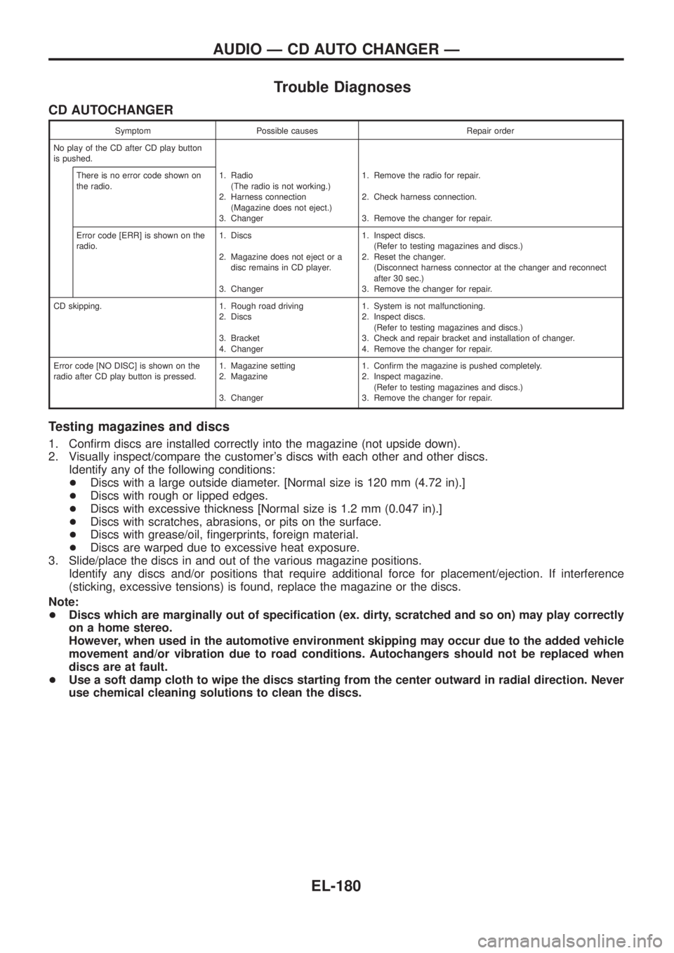
CD AUTOCHANGER
Symptom Possible causes Repair order
No play of the CD after CD play button
is pushed.
There is no error code shown on
the radio.1. Radio
(The radio is not working.)
2. Harness connection
(Magazine does not eject.)
3. Changer1. Remove the radio for repair.
2. Check harness connection.
3. Remove the changer for repair.
Error code [ERR] is shown on the
radio.1. Discs
2. Magazine does not eject or a
disc remains in CD player.
3. Changer1. Inspect discs.
(Refer to testing magazines and discs.)
2. Reset the changer.
(Disconnect harness connector at the changer and reconnect
after 30 sec.)
3. Remove the changer for repair.
CD skipping. 1. Rough road driving
2. Discs
3. Bracket
4. Changer1. System is not malfunctioning.
2. Inspect discs.
(Refer to testing magazines and discs.)
3. Check and repair bracket and installation of changer.
4. Remove the changer for repair.
Error code [NO DISC] is shown on the
radio after CD play button is pressed.1. Magazine setting
2. Magazine
3. Changer1. Con®rm the magazine is pushed completely.
2. Inspect magazine.
(Refer to testing magazines and discs.)
3. Remove the changer for repair.
Testing magazines and discs
1. Con®rm discs are installed correctly into the magazine (not upside down).
2. Visually inspect/compare the customer's discs with each other and other discs.
Identify any of the following conditions:
+Discs with a large outside diameter. [Normal size is 120 mm (4.72 in).]
+Discs with rough or lipped edges.
+Discs with excessive thickness [Normal size is 1.2 mm (0.047 in).]
+Discs with scratches, abrasions, or pits on the surface.
+Discs with grease/oil, ®ngerprints, foreign material.
+Discs are warped due to excessive heat exposure.
3. Slide/place the discs in and out of the various magazine positions.
Identify any discs and/or positions that require additional force for placement/ejection. If interference
(sticking, excessive tensions) is found, replace the magazine or the discs.
Note:
+Discs which are marginally out of speci®cation (ex. dirty, scratched and so on) may play correctly
on a home stereo.
However, when used in the automotive environment skipping may occur due to the added vehicle
movement and/or vibration due to road conditions. Autochangers should not be replaced when
discs are at fault.
+Use a soft damp cloth to wipe the discs starting from the center outward in radial direction. Never
use chemical cleaning solutions to clean the discs.
AUDIO Ð CD AUTO CHANGER Ð
EL-180
Page 541 of 1226
![NISSAN PATROL 2006 Service Manual System Description
With ignition switch in ON or START position, power is supplied
+through 7.5A fuse [No.
8, located in the fuse block (J/B)]
+to power window relay terminalj
1.
The power window rela NISSAN PATROL 2006 Service Manual System Description
With ignition switch in ON or START position, power is supplied
+through 7.5A fuse [No.
8, located in the fuse block (J/B)]
+to power window relay terminalj
1.
The power window rela](/manual-img/5/57368/w960_57368-540.png)
System Description
With ignition switch in ON or START position, power is supplied
+through 7.5A fuse [No.
8, located in the fuse block (J/B)]
+to power window relay terminalj
1.
The power window relay is energized and power is supplied
+through power window relay terminalj
5
+to power window main switch terminalj1,
+to power window sub switch terminalj
5.
MANUAL OPERATION
NOTE:
Numbers in parentheses are terminal numbers, when power window switch is pressed in the UP and DOWN
positions respectively.
Driver side
When the driver side switch in the power window main switch is pressed in the up position, power is supplied
+to driver side power window regulator terminal (j
2,j1)
+through power window main switch terminal (j
9,j8).
Ground is supplied
+to driver side power window regulator terminal (j
1,j2)
+through power window main switch terminal (j
8,j9).
Then, the motor raises or lowers the window until the switch is released.
Passenger side
MAIN SWITCH OPERATION
Power is supplied
+through power window main switch (j
5,j6)
+to front power window sub-switch (j
3,j4).
The subsequent operation is the same as the sub-switch operation.
SUB-SWITCH OPERATION
Power is supplied
+through front power window sub-switch (j
1,j2)
+to passenger side power window regulator (j
2,j1).
Ground is supplied
+to passenger side power window regulator (j
1,j2)
+through front power window sub-switch (j
2,j1)
+to front power window sub-switch (j
4,j3)
+through power window main switch (j
6,j5).
Then, the motor raises or lowers the window until the switch is released.
Rear door
Rear door windows will raise and lower in the same manner as passenger side door window.
AUTO OPERATION
The power window AUTO feature enables the driver to open or close the driver's window without holding the
window switch in the respective position.
When the AUTO switch in the main switch is pressed and released, the driver's window will travel to the fully
open or closed position.
POWER WINDOW LOCK
The power window lock is designed to lock operation of all windows except for driver's door window.
When the lock switch is pressed to lock position, ground of the sub-switches in the power window main switch
is disconnected. This prevents the power window motors from operating.
POWER WINDOW
EL-196
Page 548 of 1226
Trouble Diagnoses
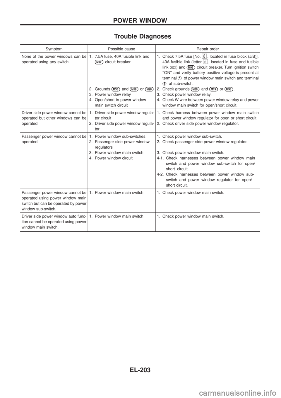
Symptom Possible cause Repair order
None of the power windows can be
operated using any switch.1. 7.5A fuse, 40A fusible link and
M92circuit breaker
2. Grounds
M30andM19orM98
3. Power window relay
4. Open/short in power window
main switch circuit1. Check 7.5A fuse [No.
8, located in fuse block (J/B)],
40A fusible link (letter
e, located in fuse and fusible
link box) and
M92circuit breaker. Turn ignition switch
``ON'' and verify battery positive voltage is present at
terminalj
1of power window main switch and terminal
j
5of sub-switch.
2. Check grounds
M30andM19orM98.
3. Check power window relay.
4. Check W wire between power window relay and power
window main switch for open/short circuit.
Driver side power window cannot be
operated but other windows can be
operated.1. Driver side power window regula-
tor circuit
2. Driver side power window regula-
tor1. Check harness between power window main switch
and power window regulator for open or short circuit.
2. Check driver side power window regulator.
Passenger power window cannot be
operated.1. Power window sub-switches
2. Passenger side power window
regulators
3. Power window main switch
4. Power window circuit1. Check power window sub-switch.
2. Check passenger side power window regulator.
3. Check power window main switch.
4-1. Check harnesses between power window main
switch and power window sub-switch for open/
short circuit.
4-2. Check harnesses between power window sub-
switch and power window regulator for open/
short circuit.
Passenger power window cannot be
operated using power window main
switch but can be operated by power
window sub-switch.1. Power window main switch 1. Check power window main switch.
Driver side power window auto func-
tion cannot be operated using power
window main switch.1. Power window main switch 1. Check power window main switch.
POWER WINDOW
EL-203
Page 549 of 1226
System Description
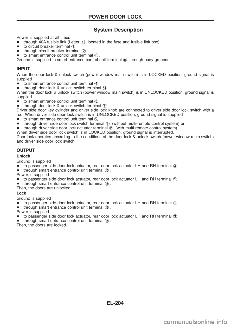
Power is supplied at all times
+through 40A fusible link (Letter
e, located in the fuse and fusible link box)
+to circuit breaker terminalj
1
+through circuit breaker terminalj2
+to smart entrance control unit terminalj11.
Ground is supplied to smart entrance control unit terminalj
18through body grounds.
INPUT
When the door lock & unlock switch (power window main switch) is in LOCKED position, ground signal is
supplied
+to smart entrance control unit terminalj
4
+through door lock & unlock switch terminalj14.
When the door lock & unlock switch (power window main switch) is in UNLOCKED position, ground signal is
supplied
+to smart entrance control unit terminalj
5
+through door lock & unlock switch terminalj7.
Driver side door key cylinder and driver side lock knob are connected to driver side door lock switch with a
rod. When driver side door lock switch is in UNLOCKED position, ground signal is supplied
+to smart entrance control unit terminalj
2
+through driver side door lock switch terminalj1(without multi-remote control system) or
+through driver side door lock actuator terminalj
2(with multi-remote control system).
When driver side door lock switch is in LOCKED position, ground signal is interrupted.
Door lock operates according to the conditions of the door lock & unlock switch (power window main switch)
and driver side door lock switch.
OUTPUT
Unlock
Ground is supplied
+to passenger side door lock actuator, rear door lock actuator LH and RH terminalj
3
+through smart entrance control unit terminalj15.
Power is supplied
+to passenger side door lock actuator, rear door lock actuator LH and RH terminalj
1
+through smart entrance control unit terminalj16.
Then, the doors are unlocked.
Lock
Ground is supplied
+to passenger side door lock actuator, rear door lock actuator LH and RH terminalj
1
+through smart entrance control unit terminalj16.
Power is supplied
+to passenger side door lock actuator, rear door lock actuator LH and RH terminalj
3
+through smart entrance control unit terminalj15.
Then, the doors are locked.
POWER DOOR LOCK
EL-204
Page 552 of 1226
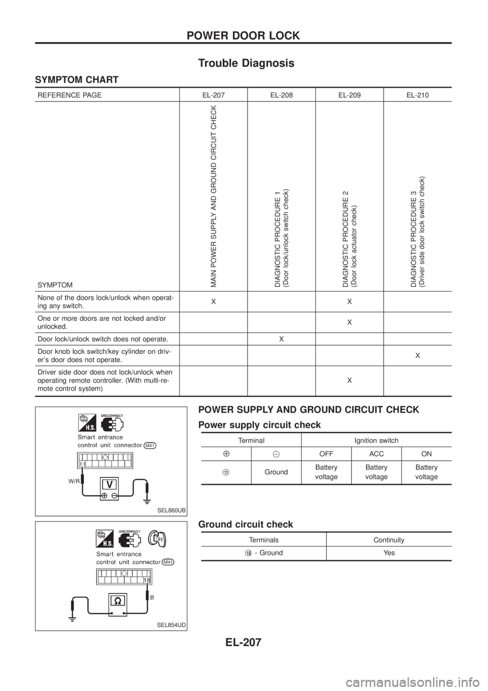
Trouble Diagnosis
SYMPTOM CHART
REFERENCE PAGE EL-207 EL-208 EL-209 EL-210
SYMPTOM
MAIN POWER SUPPLY AND GROUND CIRCUIT CHECK
DIAGNOSTIC PROCEDURE 1
(Door lock/unlock switch check)
DIAGNOSTIC PROCEDURE 2
(Door lock actuator check)
DIAGNOSTIC PROCEDURE 3
(Driver side door lock switch check)
None of the doors lock/unlock when operat-
ing any switch.XX
One or more doors are not locked and/or
unlocked.X
Door lock/unlock switch does not operate. X
Door knob lock switch/key cylinder on driv-
er's door does not operate.X
Driver side door does not lock/unlock when
operating remote controller. (With multi-re-
mote control system)X
POWER SUPPLY AND GROUND CIRCUIT CHECK
Power supply circuit check
Terminal Ignition switch
Å@OFF ACC ON
j
11GroundBattery
voltageBattery
voltageBattery
voltage
Ground circuit check
Terminals Continuity
j
18- Ground Yes
SEL860UB
SEL854UD
POWER DOOR LOCK
EL-207
Page 553 of 1226
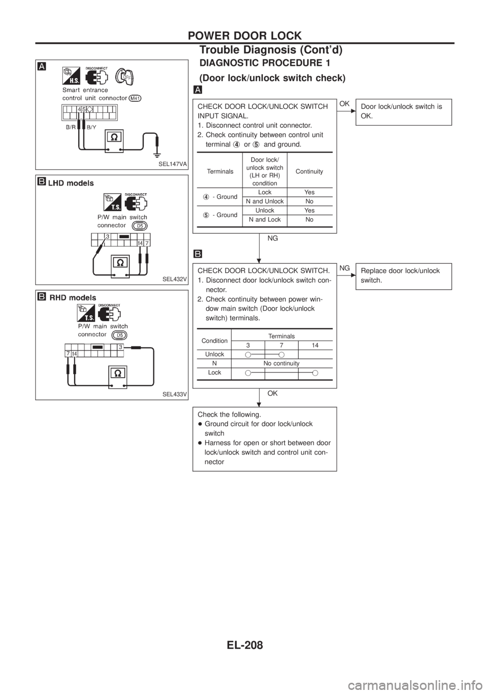
DIAGNOSTIC PROCEDURE 1
(Door lock/unlock switch check)
CHECK DOOR LOCK/UNLOCK SWITCH
INPUT SIGNAL.
1. Disconnect control unit connector.
2. Check continuity between control unit
terminalj
4orj5and ground.
NG
cOK
Door lock/unlock switch is
OK.
CHECK DOOR LOCK/UNLOCK SWITCH.
1. Disconnect door lock/unlock switch con-
nector.
2. Check continuity between power win-
dow main switch (Door lock/unlock
switch) terminals.
OK
cNG
Replace door lock/unlock
switch.
Check the following.
+Ground circuit for door lock/unlock
switch
+Harness for open or short between door
lock/unlock switch and control unit con-
nector
TerminalsDoor lock/
unlock switch
(LH or RH)
conditionContinuity
j
4- GroundLock Yes
N and Unlock No
j
5- GroundUnlock Yes
N and Lock No
ConditionTerminals3714
Unlockjj
N No continuity
Lockjj
SEL147VA
SEL432V
SEL433V
.
.
POWER DOOR LOCK
Trouble Diagnosis (Cont'd)
EL-208