Page 365 of 1226
CEL721
GROUND DISTRIBUTION/LHD MODELS
Main Harness (Cont'd)
EL-20
Page 366 of 1226
CEL722
GROUND DISTRIBUTION/LHD MODELS
Main Harness (Cont'd)
EL-21
Page 375 of 1226
Main Harness
CEL803
GROUND DISTRIBUTION/RHD MODELS
EL-30
Page 376 of 1226
CEL804
GROUND DISTRIBUTION/RHD MODELS
Main Harness (Cont'd)
EL-31
Page 377 of 1226
CEL805
GROUND DISTRIBUTION/RHD MODELS
Main Harness (Cont'd)
EL-32
Page 382 of 1226

CAUTION:
If it becomes necessary to start the engine with a booster bat-
tery and jumper cables,
a. Use a 12-volt booster battery.
b. After connecting battery cables, ensure that they are
tightly clamped to battery terminals for good contact.
c. Never add distilled water through the hole used to check
speci®c gravity.
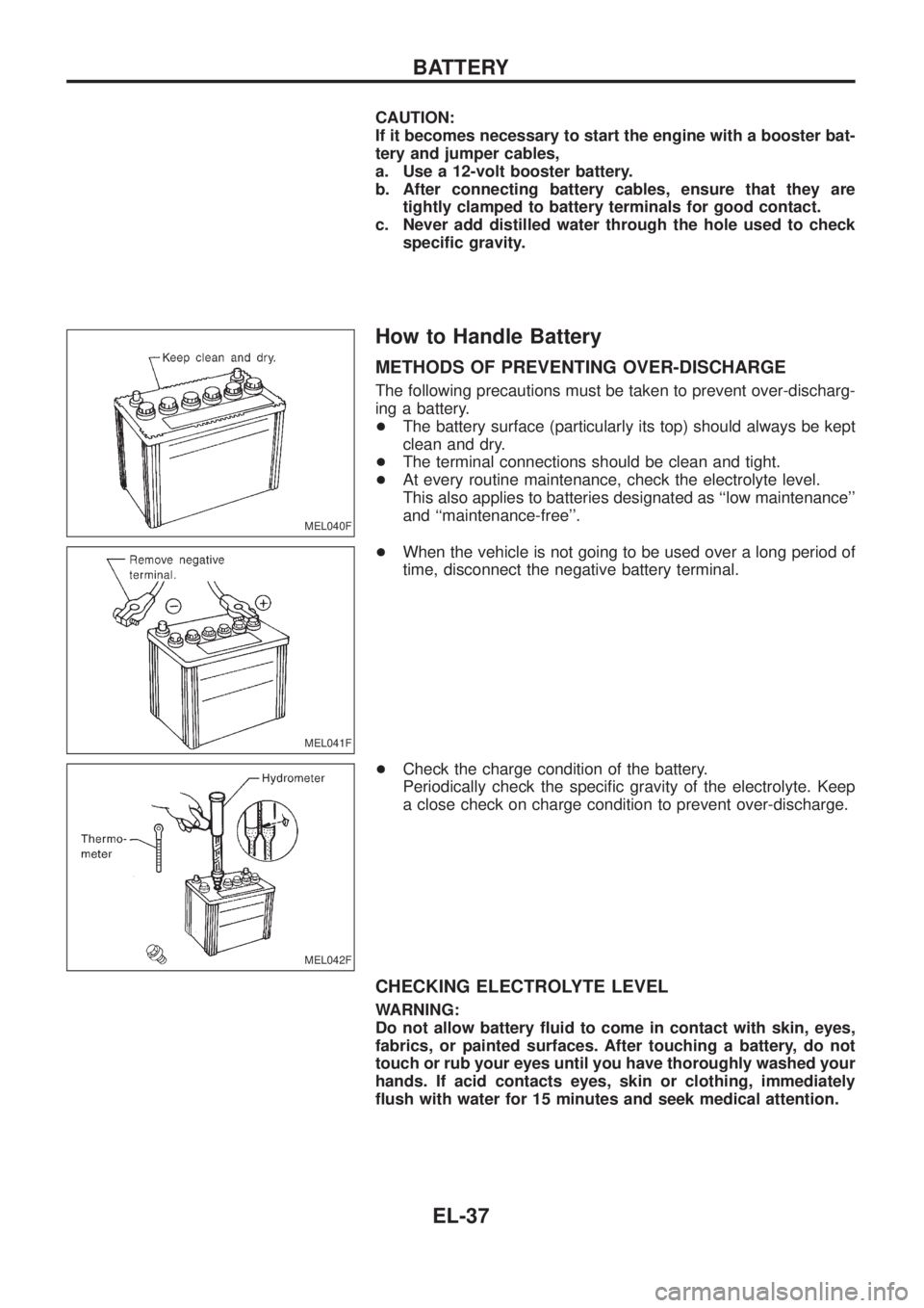
How to Handle Battery
METHODS OF PREVENTING OVER-DISCHARGE
The following precautions must be taken to prevent over-discharg-
ing a battery.
+The battery surface (particularly its top) should always be kept
clean and dry.
+The terminal connections should be clean and tight.
+At every routine maintenance, check the electrolyte level.
This also applies to batteries designated as ``low maintenance''
and ``maintenance-free''.
+When the vehicle is not going to be used over a long period of
time, disconnect the negative battery terminal.
+Check the charge condition of the battery.
Periodically check the speci®c gravity of the electrolyte. Keep
a close check on charge condition to prevent over-discharge.
CHECKING ELECTROLYTE LEVEL
WARNING:
Do not allow battery ¯uid to come in contact with skin, eyes,
fabrics, or painted surfaces. After touching a battery, do not
touch or rub your eyes until you have thoroughly washed your
hands. If acid contacts eyes, skin or clothing, immediately
¯ush with water for 15 minutes and seek medical attention.
MEL040F
MEL041F
MEL042F
BATTERY
EL-37
Page 409 of 1226
LOW BEAM
1. Turn headlamp low beam on.
2. Use adjusting screws to perform aiming adjustment.
+First tighten the adjusting screw all the way and then make
adjustment by loosening the screw.
+Adjust headlamps so that main axis of light is parallel to
center line of body and is aligned with point P shown in
illustration.
+Figure to the left shows headlamp aiming pattern for driv-
ing on right side of road; for driving on left side of road,
aiming pattern is reversed.
+Dotted lines in illustration show center of headlamp.
``H'': Horizontal center line of headlamps
``W
L'': Distance between each headlamp center
``L'': 5,000 mm (196.85 in)
``C'': 63 mm (2.48 in)
CEL735
SEL254I
HEADLAMP Ð Conventional Type Ð
Aiming Adjustment (Cont'd)
EL-64
Page 458 of 1226

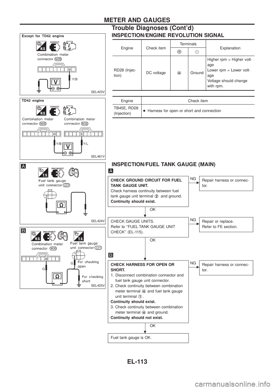
INSPECTION/ENGINE REVOLUTION SIGNAL
Engine Check itemTerminals
ExplanationÅ@
RD28 (Injec-
tion)DC voltagej
44GroundHigher rpm = Higher volt-
age
Lower rpm = Lower volt-
age
Voltage should change
with rpm.
Engine Check item
TB45E, RD28
(Injection)+Harness for open or short and connection
INSPECTION/FUEL TANK GAUGE (MAIN)
CHECK GROUND CIRCUIT FOR FUEL
TANK GAUGE UNIT.
Check harness continuity between fuel
tank gauge unit terminalj
2and ground.
Continuity should exist.
OK
cNG
Repair harness or connec-
tor.
CHECK GAUGE UNITS.
Refer to ``FUEL TANK GAUGE UNIT
CHECK'' (EL-115).
OK
cNG
Repair or replace.
Refer to FE section.
CHECK HARNESS FOR OPEN OR
SHORT.
1. Disconnect combination connector and
fuel tank gauge unit connector.
2. Check continuity between combination
meter terminalj
46and fuel tank gauge
unit terminalj
1.
Continuity should exist.
3. Check continuity between combination
meter terminalj
46and ground.
Continuity should not exist.
OK
cNG
Repair harness or connec-
tor.
Fuel tank gauge is OK.
SEL423V
SEL461V
SEL424V
SEL425V
.
.
.
METER AND GAUGES
Trouble Diagnoses (Cont'd)
EL-113