Page 215 of 1226
TEC421
TROUBLE DIAGNOSIS FOR POWER SUPPLY
Main Power Supply and Ground Circuit
(Cont'd)
EC-64
Page 216 of 1226
TEC422
TROUBLE DIAGNOSIS FOR POWER SUPPLY
Main Power Supply and Ground Circuit
(Cont'd)
EC-65
Page 217 of 1226

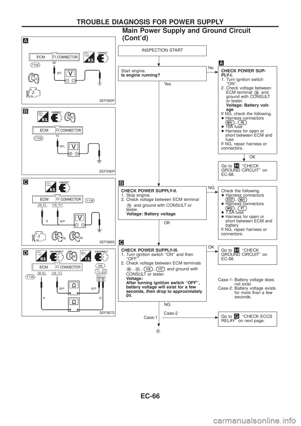
INSPECTION START
Start engine.
Is engine running?
Ye s
cNo
CHECK POWER SUP-
PLY-I.
1. Turn ignition switch
``ON''.
2. Check voltage between
ECM terminal
V38and
ground with CONSULT
or tester.
Voltage: Battery volt-
age
If NG, check the following.
+Harness connectors
M51,F6+10A fuse
+Harness for open or
short between ECM and
fuse
If NG, repair harness or
connectors.
OK
Go to
``CHECK
GROUND CIRCUIT'' on
EC-68.
CHECK POWER SUPPLY-II.
1. Stop engine.
2. Check voltage between ECM terminal
V70and ground with CONSULT or
tester.
Voltage: Battery voltage
OK
cNG
Check the following.
+Harness connectors
E127,M21+Harness connectorsM52,F7+7.5A fuse
+Harness for open or
short between ECM and
battery
If NG, repair harness or
connectors.
CHECK POWER SUPPLY-III.
1. Turn ignition switch ``ON'' and then
``OFF''.
2. Check voltage between ECM terminals
V56,V61,11 6,11 7and ground with
CONSULT or tester.
Voltage:
After turning ignition switch ``OFF'',
battery voltage will exist for a few
seconds, then drop to approximately
0V.
NG
cOK
Go to``CHECK
GROUND CIRCUIT'' on
EC-68.
Case-1: Battery voltage does
not exist.
Case-2: Battery voltage exists
for more than a few
seconds.
Case-1
cCase-2
Go to``CHECK ECCS
RELAY'' on next page.
jA
SEF065P
SEF056R
SEF566S
SEF567S
.
.
.
.
.
TROUBLE DIAGNOSIS FOR POWER SUPPLY
Main Power Supply and Ground Circuit
(Cont'd)
EC-66
Page 218 of 1226

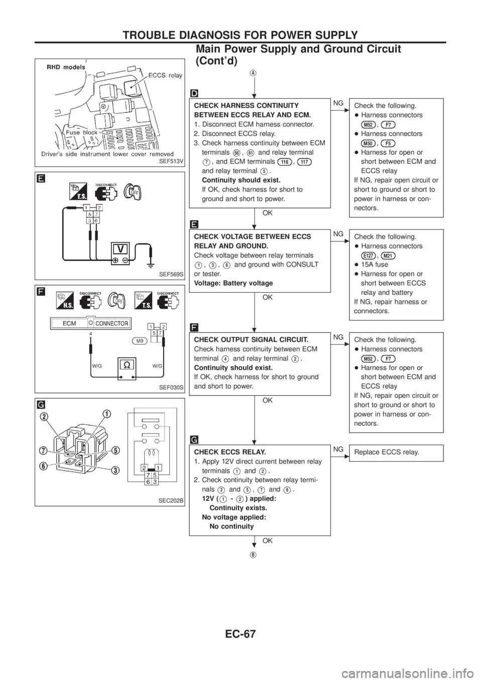
jA
CHECK HARNESS CONTINUITY
BETWEEN ECCS RELAY AND ECM.
1. Disconnect ECM harness connector.
2. Disconnect ECCS relay.
3. Check harness continuity between ECM
terminals
V56,V61and relay terminal
V7, and ECM terminals11 6,11 7
and relay terminalV5.
Continuity should exist.
If OK, check harness for short to
ground and short to power.
OK
cNG
Check the following.
+Harness connectors
M52,F7
+Harness connectors
M50,F5
+Harness for open or
short between ECM and
ECCS relay
If NG, repair open circuit or
short to ground or short to
power in harness or con-
nectors.
CHECK VOLTAGE BETWEEN ECCS
RELAY AND GROUND.
Check voltage between relay terminals
V1,V3,V6and ground with CONSULT
or tester.
Voltage: Battery voltage
OK
cNG
Check the following.
+Harness connectors
E127,M21
+15A fuse
+Harness for open or
short between ECCS
relay and battery
If NG, repair harness or
connectors.
CHECK OUTPUT SIGNAL CIRCUIT.
Check harness continuity between ECM
terminal
V4and relay terminalV2.
Continuity should exist.
If OK, check harness for short to ground
and short to power.
OK
cNG
Check the following.
+Harness connectors
M52,F7
+Harness for open or
short between ECM and
ECCS relay
If NG, repair open circuit or
short to ground or short to
power in harness or con-
nectors.
CHECK ECCS RELAY.
1. Apply 12V direct current between relay
terminals
V1andV2.
2. Check continuity between relay termi-
nals
V3andV5,V7andV6.
12V (
V1-V2) applied:
Continuity exists.
No voltage applied:
No continuity
OK
cNG
Replace ECCS relay.
jB
SEF513V
SEF569S
SEF030S
SEC202B
.
.
.
.
.
TROUBLE DIAGNOSIS FOR POWER SUPPLY
Main Power Supply and Ground Circuit
(Cont'd)
EC-67
Page 219 of 1226
jB
CHECK GROUND CIRCUIT.
1. Turn ignition switch ``OFF''.
2. Disconnect ECM harness connector.
3. Check harness continuity between ECM
terminals
V39,V43,106,11 2,11 8
and engine ground.
Continuity should exist.
If OK, check harness for short to
ground and short to power.
OK
cNG
Check the following.
+Joint connector
F18
+Harness for open or
short between ECM and
ground
If NG, repair open circuit or
short to ground or short to
power in harness or con-
nectors.
Check ECM pin terminals for damage and
check the connection of ECM harness
connector.
INSPECTION END
SEF570S
.
.
.
TROUBLE DIAGNOSIS FOR POWER SUPPLY
Main Power Supply and Ground Circuit
(Cont'd)
EC-68
Page 225 of 1226

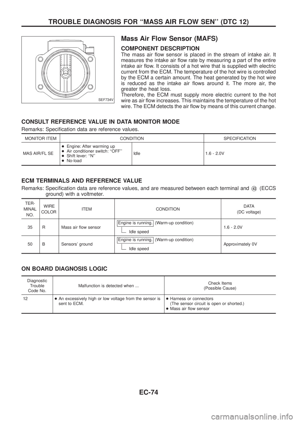
Mass Air Flow Sensor (MAFS)
COMPONENT DESCRIPTION
The mass air ¯ow sensor is placed in the stream of intake air. It
measures the intake air ¯ow rate by measuring a part of the entire
intake air ¯ow. It consists of a hot wire that is supplied with electric
current from the ECM. The temperature of the hot wire is controlled
by the ECM a certain amount. The heat generated by the hot wire
is reduced as the intake air ¯ows around it. The more air, the
greater the heat loss.
Therefore, the ECM must supply more electric current to the hot
wire as air ¯ow increases. This maintains the temperature of the hot
wire. The ECM detects the air ¯ow by means of this current change.
CONSULT REFERENCE VALUE IN DATA MONITOR MODE
Remarks: Speci®cation data are reference values.
MONITOR ITEM CONDITION SPECIFICATION
MAS AIR/FL SE+Engine: After warming up
+Air conditioner switch: ``OFF''
+Shift lever: ``N''
+No-loadIdle 1.6 - 2.0V
ECM TERMINALS AND REFERENCE VALUE
Remarks: Speci®cation data are reference values, and are measured between each terminal andV43(ECCS
ground) with a voltmeter.
TER-
MINAL
NO.WIRE
COLORITEM CONDITIONDATA
(DC voltage)
35 R Mass air ¯ow sensorEngine is running.
(Warm-up condition)
Idle speed1.6 - 2.0V
50 B Sensors' groundEngine is running.
(Warm-up condition)
Idle speedApproximately 0V
ON BOARD DIAGNOSIS LOGIC
Diagnostic
Trouble
Code No.Malfunction is detected when ...Check Items
(Possible Cause)
12+An excessively high or low voltage from the sensor is
sent to ECM.+Harness or connectors
(The sensor circuit is open or shorted.)
+Mass air ¯ow sensor
SEF734V
TROUBLE DIAGNOSIS FOR ``MASS AIR FLOW SEN'' (DTC 12)
EC-74
Page 248 of 1226
TER-
MINAL
NO.WIRE
COLORITEM CONDITIONDATA
(DC Voltage and Pulse
Signal)
102
108G/Y Electric governor groundEngine is running.
Idle speedApproximately 10V
SEF727V
Engine is running.
Engine speed is 2,000 rpm.Approximately 10V
SEF728V
11 6
11 7W Power supply for ECM Ignition switch ``ON''BATTERY VOLTAGE
(11 - 14V)
ON BOARD DIAGNOSIS LOGIC
Diagnostic
Trouble Code
No.Malfunction is detected when ....Check Items
(Possible cause)
18, 22, 25+Fuel injection feedback system does not operate prop-
erly. (This system consists essentially of ECM, electric
governor and control sleeve position sensor.)+Main power supply circuit (ECM terminals
11 6,11 7)
and fuse
+Harness or connectors
(Electric governor and control sleeve position sensor
circuit)
+Electric governor
+Electronic fuel injection pump
+ECM
TROUBLE DIAGNOSIS FOR ``F/INJ F/B 2'' (DTC 18),
``F/INJ F/B'' (DTC 22), ``ELECTRIC GOV'' (DTC 25)
Electric Governor (Cont'd)
EC-97
Page 265 of 1226

TER-
MINAL
NO.WIRE
COLORITEM CONDITIONDATA
(DC Voltage and Pulse
Signal)
15 Y/L Air conditioner relayEngine is running.
Air conditioner switch is ``OFF''.BATTERY VOLTAGE
(11 - 14V)
Engine is running.
Both air conditioner switch and blower fan
switch are ``ON''.
(Compressor is operating.)0-1V
ON BOARD DIAGNOSIS LOGIC
This diagnosis continuously monitors the engine coolant temperature.
If the cooling fan or another component in the cooling system malfunctions, engine coolant temperature will
rise.
When the engine coolant temperature reaches an abnormally high temperature condition, a malfunction is
indicated.
Diagnostic Trouble
Code No.Malfunction is detected when ...Check Items
(Possible Cause)
28+Cooling fan does not operate properly (Overheat).
+Cooling fan system does not operate properly (Over-
heat).
+Engine coolant was not added to the system using
the proper ®lling method.+Harness or connectors
(The cooling fan circuit is open or shorted.)
+Cooling fan
+Radiator hose
+Radiator
+Radiator cap
+Water pump
+Thermostat
+Fan belt
+Engine coolant temperature sensor
For more information, refer to ``MAIN 12
CAUSES OF OVERHEATING'', EC-120.
CAUTION:
When a malfunction is indicated, be sure to replace the coolant following the procedure in the MA
section (``Changing Engine Coolant'', ``ENGINE MAINTENANCE''). Also, replace the engine oil.
a. Fill radiator with coolant up to speci®ed level with a ®lling speed of 2 liters per minute. Be sure to
use coolant with the proper mixture ratio. Refer to MA section (``Anti-freeze Coolant Mixture Ratio'',
``RECOMMENDED FLUIDS AND LUBRICANTS'').
b. After re®lling coolant, run engine to ensure that no water-¯ow noise is emitted.
TROUBLE DIAGNOSIS FOR ``OVER HEAT'' (DTC 28)
Cooling Fan (Overheat) (Cont'd)
EC-114