Page 1011 of 1226
Replacing Rear Oil Seal
REMOVAL
1. Remove transfer assembly. Ð Refer to TF section.
2. Pull out rear oil seal.
INSTALLATION
1. Install rear oil seal.
+Before installing apply multi-purpose grease to seal lip.
2. Install transfer assembly. Ð Refer to TF section.
Position Switch Check
Switch Gear position Continuity
Reverse position switchReverse Yes
Except reverse No
Neutral position switchNeutral Yes
Except neutral No
SMT321B
SMT322B
SMT274D
ON-VEHICLE SERVICE
MT-4
Page 1012 of 1226
Removal
1. Remove front and rear propeller shafts. Refer to PD section
(``Removal and Installation'', ``PROPELLER SHAFT'').
2. Remove clutch operating cylinder.
3. Remove exhaust front and rear tubes. Refer to FE section
(``EXHAUST SYSTEM'').
4. Disconnect vehicle speed sensor, back-up lamp switch, 4WD
switch and neutral position switch harness connector.
5. Remove center brake cable. Refer to BR section.
6. Remove shift lever of transmission. Refer to MT-12 (RS5R30A).
7. Remove transfer control lever. Refer to TF section (``Removal'',
``REMOVAL AND INSTALLATION'').
8. Support engine by placing a jack under oil pan.
+Do not place jack under the oil pan drain plug.
9. Remove transmission with transfer from engine.
WARNING:
Support Manual Transmission with transfer, while removing it.
SMT321D
REMOVAL AND INSTALLATION
MT-5
Page 1021 of 1226
5. Remove front cover and gasket.
6. Remove stopper ring and main drive bearing snap ring.
7. Remove transmission case by tapping lightly.
8. Remove front cover oil seal.
Shift Control Components
1. Mount adapter plate on vise.
2. Remove OD & reverse fork rod.
SMT370A
SMT371A
SMT822C
SMT392A
SMT823C
DISASSEMBLY
Case Components (Cont'd)
MT-14
Page 1036 of 1226
Shift Control Components
1. Install OD fork rod and OD shift fork. Then install retaining pin
into OD shift fork.
2. Install 1st & 2nd, 3rd & 4th and reverse shift fork onto coupling
sleeve.
3. Install striking rod into hole of shift forks, striking lever and
interlock and then install retaining pin into striking lever.
+Make sure that striking rod moves smoothly.
Case Components
1. Install front cover oil seal.
+Apply multi-purpose grease to seal lip.
2. Install selected counter gear front bearing shim onto transmis-
sion case.
+Apply multi-purpose grease.
3. Apply sealant to mating surface of transmission case.
4. Install gear assembly onto transmission case.
5. Install check spring and check ball into interlock stopper.
+Apply multi-purpose grease to check ball.
6. Install interlock stopper assembly and then tighten check ball
plug.
+Apply sealant to thread of check ball plug.
SMT834C
SMT374AA
SMT393AA
SMT835C
SMT460A
ASSEMBLY
MT-29
Page 1039 of 1226
General Speci®cations
Applied modelRD28ETi
4WD
Transmission FS5R30A
Number of speed 5
Transmission control Floor direct
Shift pattern
Synchromesh type Warner
Gear ratio
1st 4.061
2nd 2.357
3rd 1.490
4th 1.000
OD 0.862
Reverse 4.125
Number of teeth
Mainshaft
Drive 20
1st 32
2nd 30
3rd 28
OD 23
Reverse 30
Countershaft
Drive 33
1st 13
2nd 21
3rd 31
OD 44
Reverse 12
Reverse idler gear 22
Oil capacity!(Imp pt) 5.1 (9)
Remarks2nd & 3rd double baulk ring
type synchronizer
Reverse breaking mechanism type
SERVICE DATA AND SPECIFICATIONS (SDS)
MT-32
Page 1042 of 1226

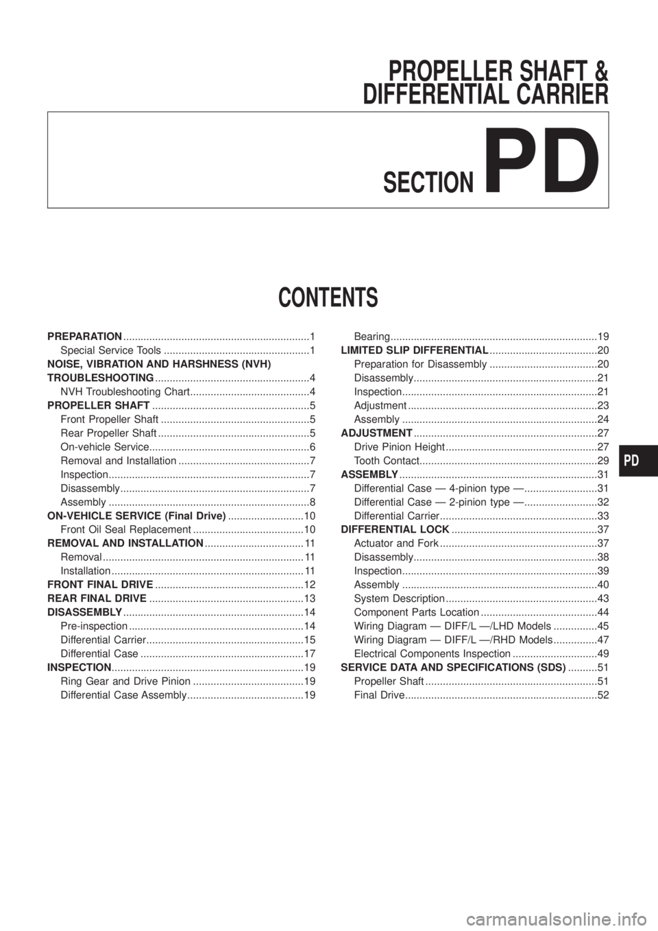
PROPELLER SHAFT &
DIFFERENTIAL CARRIER
SECTION
PD
CONTENTS
PREPARATION................................................................1
Special Service Tools ..................................................1
NOISE, VIBRATION AND HARSHNESS (NVH)
TROUBLESHOOTING.....................................................4
NVH Troubleshooting Chart.........................................4
PROPELLER SHAFT......................................................5
Front Propeller Shaft ...................................................5
Rear Propeller Shaft ....................................................5
On-vehicle Service.......................................................6
Removal and Installation .............................................7
Inspection.....................................................................7
Disassembly.................................................................7
Assembly .....................................................................8
ON-VEHICLE SERVICE (Final Drive)..........................10
Front Oil Seal Replacement ......................................10
REMOVAL AND INSTALLATION.................................. 11
Removal ..................................................................... 11
Installation .................................................................. 11
FRONT FINAL DRIVE...................................................12
REAR FINAL DRIVE.....................................................13
DISASSEMBLY..............................................................14
Pre-inspection ............................................................14
Differential Carrier......................................................15
Differential Case ........................................................17
INSPECTION..................................................................19
Ring Gear and Drive Pinion ......................................19
Differential Case Assembly........................................19Bearing.......................................................................19
LIMITED SLIP DIFFERENTIAL.....................................20
Preparation for Disassembly .....................................20
Disassembly...............................................................21
Inspection...................................................................21
Adjustment .................................................................23
Assembly ...................................................................24
ADJUSTMENT...............................................................27
Drive Pinion Height ....................................................27
Tooth Contact.............................................................29
ASSEMBLY....................................................................31
Differential Case Ð 4-pinion type Ð.........................31
Differential Case Ð 2-pinion type Ð.........................32
Differential Carrier......................................................33
DIFFERENTIAL LOCK..................................................37
Actuator and Fork ......................................................37
Disassembly...............................................................38
Inspection...................................................................39
Assembly ...................................................................40
System Description ....................................................43
Component Parts Location ........................................44
Wiring Diagram Ð DIFF/L Ð/LHD Models ...............45
Wiring Diagram Ð DIFF/L Ð/RHD Models ...............47
Electrical Components Inspection .............................49
SERVICE DATA AND SPECIFICATIONS (SDS)..........51
Propeller Shaft ...........................................................51
Final Drive..................................................................52
PD
Page 1045 of 1226
Tool number
Tool nameDescription Unit application
H233B
KV381025S0
Oil seal ®tting tool
V1ST30720000
Drift bar
V2KV38102510
Drift
NT525
Installing front oil seal
X
a: 77 mm (3.03 in) dia.
b: 55 mm (2.17 in) dia.
c: 71 mm (2.80 in) dia.
d: 65 mm (2.56 in) dia.
ST32580000
Differentialsidebearing
adjustingnutwrench
ST3125S001 Drive pinion setting gauge set 1 ST3131251000 Height Gauge 2 ST31181001
Dummy Shaft
3 KV38108700 Spacer [thickness: 2.00 mm (0.0787 in)]
NT141
Adjusting side bearing pre-
load and backlash (ring gear-
drive pinion)
X
X
PREPARATION
Special Service Tools (Cont'd)
PD-3
Page 1046 of 1226
NVH Troubleshooting Chart
Use the chart below to help you ®nd the cause of the symptom. If necessary, repair or replace these parts.
Reference pageÐ
Ð
PD-6
PD-6
PD-19
PD-29
PD-19
PD-14
Ð
Refer to MA section.
Refer to PROPELLER SHAFT in this chart.
Refer to DIFFERENTIAL in this chart.
NVH in FA, RA section
NVH in FA section
NVH in FA section
NVH in RA section
NVH in BR section
NVH in ST section
Possible cause and
SUSPECTED PARTS
Uneven rotation torque
Excessive joint angle
Rotation imbalance
Excessive runout
Rough gear tooth
Improper gear contact
Tooth surfaces worn
Incorrect backlash
Companion ¯ange excessive runout
Improper gear oil
PROPELLER SHAFT
DIFFERENTIAL
AXLE AND SUSPENSION
TIRES
ROAD WHEEL
DRIVE SHAFT
BRAKES
STEERING
SymptomPRO-
PELLER
SHAFTNoiseXXXX XXXXXXX
Shake XXXXXXX
VibrationXXXX XX X X
DIFFER-
ENTIALNoiseXXXXXXX XXXXXX
X: Applicable
NOISE, VIBRATION AND HARSHNESS (NVH) TROUBLESHOOTING
PD-4