Page 1073 of 1226
Differential Case Ð 4-pinion type Ð
1. Measure clearance between side gear thrust washer and dif-
ferential case.
Clearance between side gear thrust washer
and differential case (A Ð B):
0.15 - 0.20 mm (0.0059 - 0.0079 in)
The clearance can be adjusted with side gear thrust washer.
Refer to SDS.
2. Apply oil to gear tooth surfaces and thrust surfaces and check
that they turn properly.
3. Install differential case LH and RH.
4. Place differential case on ring gear.
5. Apply locking sealer to ring gear bolts, and install them.
Tighten bolts in a criss-cross fashion, lightly tapping bolt head
with a hammer.
6. Press-®t side bearing inner races on differential case with Tool.
Tool number:
j
AST33190000
j
BST02371000
SPD656
SPD643
SPD746
PD353
ASSEMBLY
PD-31
Page 1074 of 1226
Differential Case Ð 2-pinion type Ð
1. Install side gears, pinion mate gears and thrust washers into
differential case.
2. Fit pinion mate shaft to differential case so that it meets lock pin
holes.
3. Adjust backlash between side gear and pinion mate gear by
selecting side gear thrust washer. Refer to SDS.
Backlash between side gear and pinion mate gear
(Clearance between side gear thrust washer and dif-
ferential case):
0.15 - 0.20 mm (0.0059 - 0.0079 in)
4. Install pinion mate shaft lock pin with a punch.
Make sure lock pin is ¯ush with case.
5. Apply gear oil to gear tooth surfaces and thrust surfaces and
make sure they turn properly.
6. Install differential case assembly on ring gear.
Tighten bolts in a criss-cross pattern, lightly tapping bolt head
with a hammer.
7. Press-®t side bearing inner cones on differential case with Tool.
Tool number:
j
AST33190000
j
BST02371000
SPD552
SPD258
SPD030
SPD322
PD353
ASSEMBLY
PD-32
Page 1075 of 1226
Differential Carrier
1. Press-®t front and rear bearing outer races with Tools.
Tool number:
j
AST30611000
j
BST30621000 (front differential)
or suitable pipe
j
CST30701000
CAUTION:
Do not damage roller side face.
2. Select drive pinion height adjusting washer. Refer to ADJUST-
MENT (PD-27).
3. Install drive pinion height adjusting washer in drive pinion, and
press-®t pinion rear bearing inner cone in it, with press and
Tool.
Tool number: ST30911000
4. Place pinion front bearing inner cone in gear carrier.
5. Apply multi-purpose grease to cavity at sealing lips of oil seal.
Install front oil seal.
Tool number:
j
AST30720000
j
BKV38102510
SPD580
SPD377
SPD581
SPD451A
ASSEMBLY
PD-33
Page 1076 of 1226

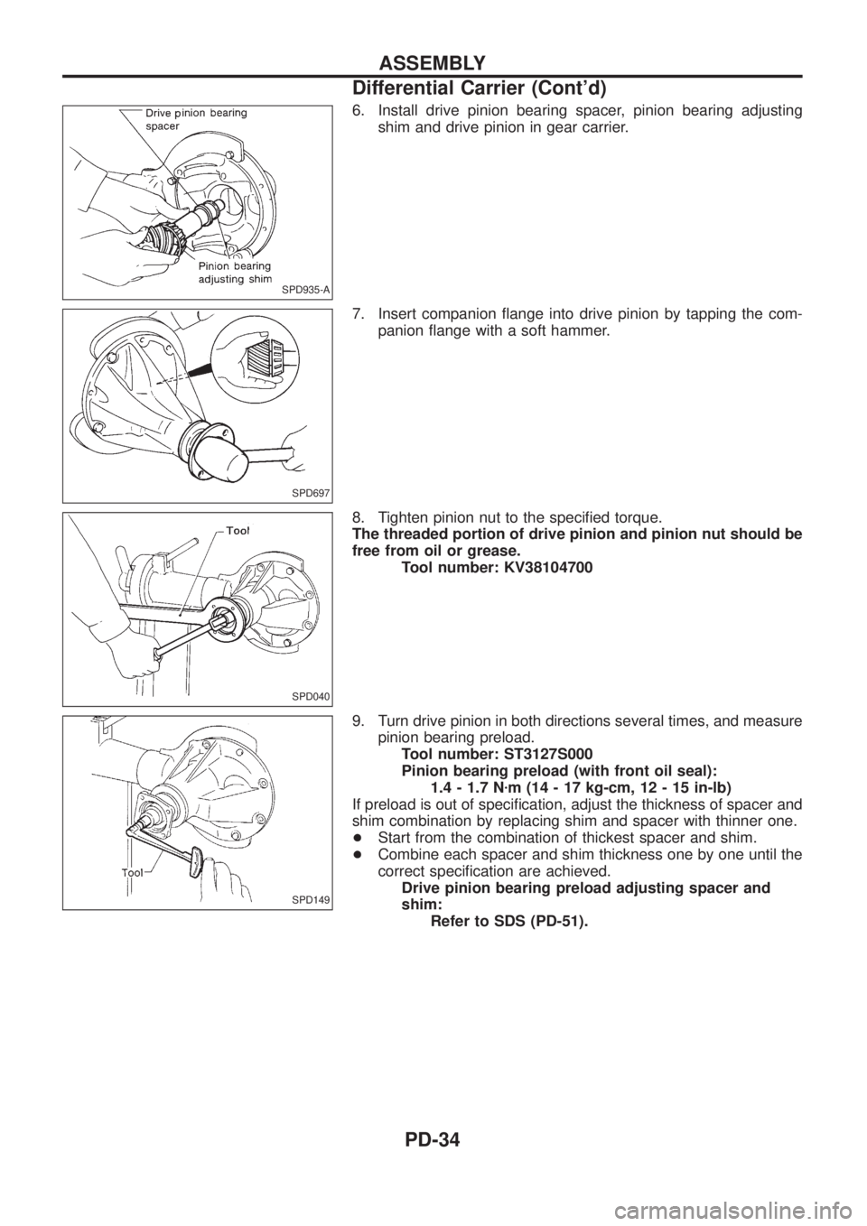
6. Install drive pinion bearing spacer, pinion bearing adjusting
shim and drive pinion in gear carrier.
7. Insert companion ¯ange into drive pinion by tapping the com-
panion ¯ange with a soft hammer.
8. Tighten pinion nut to the speci®ed torque.
The threaded portion of drive pinion and pinion nut should be
free from oil or grease.
Tool number: KV38104700
9. Turn drive pinion in both directions several times, and measure
pinion bearing preload.
Tool number: ST3127S000
Pinion bearing preload (with front oil seal):
1.4 - 1.7 Nzm (14 - 17 kg-cm, 12 - 15 in-lb)
If preload is out of speci®cation, adjust the thickness of spacer and
shim combination by replacing shim and spacer with thinner one.
+Start from the combination of thickest spacer and shim.
+Combine each spacer and shim thickness one by one until the
correct speci®cation are achieved.
Drive pinion bearing preload adjusting spacer and
shim:
Refer to SDS (PD-51).
SPD935-A
SPD697
SPD040
SPD149
ASSEMBLY
Differential Carrier (Cont'd)
PD-34
Page 1077 of 1226

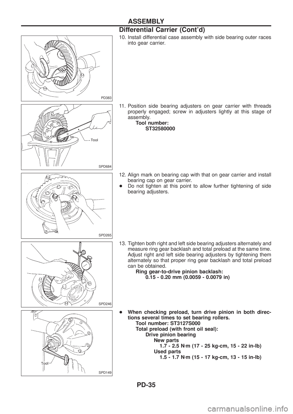
10. Install differential case assembly with side bearing outer races
into gear carrier.
11. Position side bearing adjusters on gear carrier with threads
properly engaged; screw in adjusters lightly at this stage of
assembly.
Tool number:
ST32580000
12. Align mark on bearing cap with that on gear carrier and install
bearing cap on gear carrier.
+Do not tighten at this point to allow further tightening of side
bearing adjusters.
13. Tighten both right and left side bearing adjusters alternately and
measure ring gear backlash and total preload at the same time.
Adjust right and left side bearing adjusters by tightening them
alternately so that proper ring gear backlash and total preload
can be obtained.
Ring gear-to-drive pinion backlash:
0.15 - 0.20 mm (0.0059 - 0.0079 in)
+When checking preload, turn drive pinion in both direc-
tions several times to set bearing rollers.
Tool number: ST3127S000
Total preload (with front oil seal):
Drive pinion bearing
New parts
1.7 - 2.5 Nzm (17 - 25 kg-cm, 15 - 22 in-lb)
Used parts
1.5 - 1.7 Nzm (15 - 17 kg-cm, 13 - 15 in-lb)
PD383
SPD684
SPD265
SPD246
SPD149
ASSEMBLY
Differential Carrier (Cont'd)
PD-35
Page 1081 of 1226
Inspection
CONTACT SURFACES
1. Clean the disassembled parts in suitable solvent and blow dry
with compressed air.
2. If following surfaces are found with burrs or scratches, smooth
with oil stone.
V1Differential case A
V2Differential case B
V3Side gear thrust washer
V4Side gear
V5Pinion mate thrust washer
V6Pinion mate gear
V7Pinion mate shaft
ACTUATOR OPERATION
Apply a vacuum pressure of 66.7 kPa (667 mbar, 500 mmHg, 19.69
inHg) and check its operation and leakage within 10 seconds.
SPD842
SPD906
DIFFERENTIAL LOCK
PD-39
Page 1094 of 1226

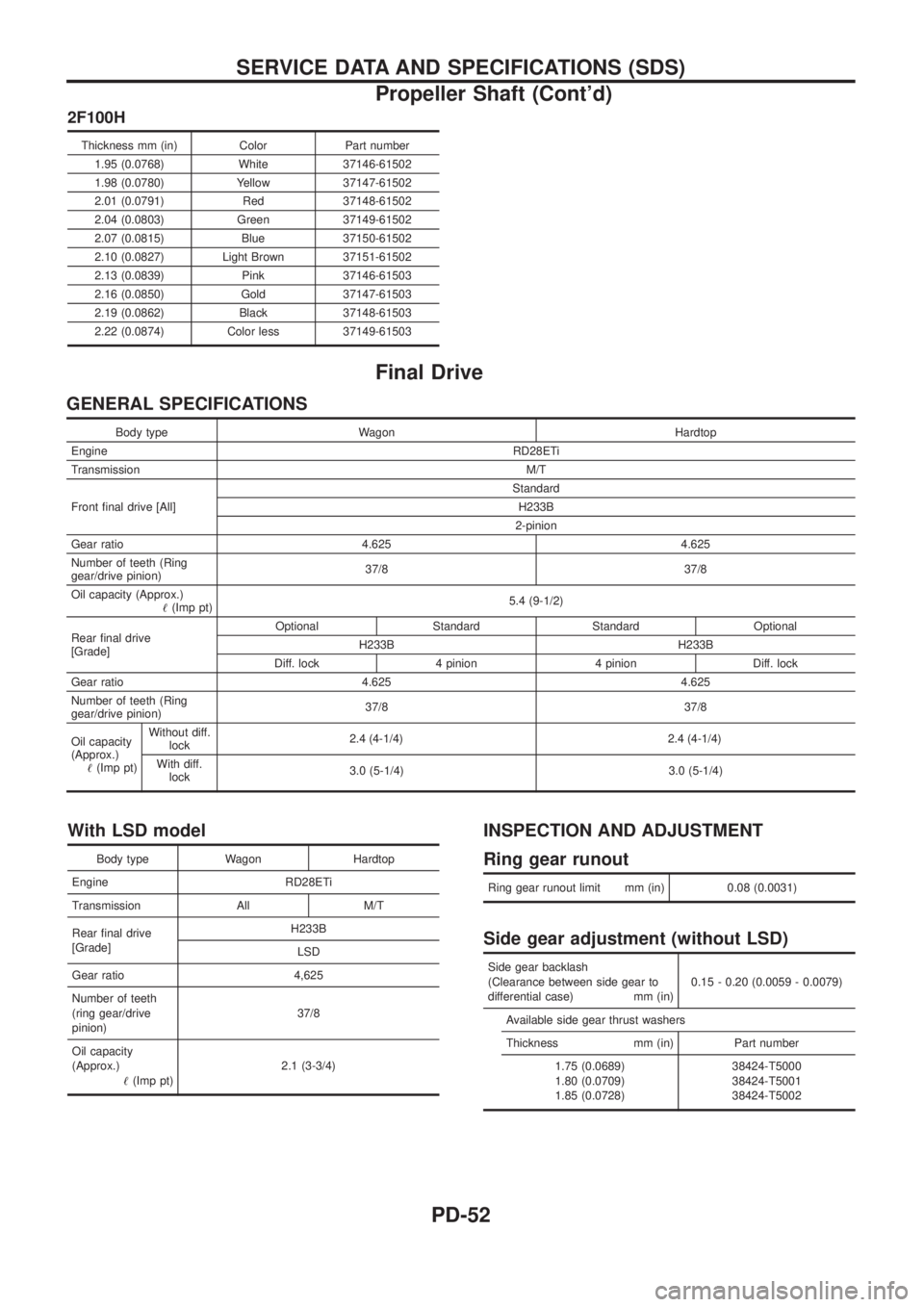
2F100H
Thickness mm (in) Color Part number1.95 (0.0768) White 37146-61502
1.98 (0.0780) Yellow 37147-61502
2.01 (0.0791) Red 37148-61502
2.04 (0.0803) Green 37149-61502
2.07 (0.0815) Blue 37150-61502
2.10 (0.0827) Light Brown 37151-61502
2.13 (0.0839) Pink 37146-61503
2.16 (0.0850) Gold 37147-61503
2.19 (0.0862) Black 37148-61503
2.22 (0.0874) Color less 37149-61503
Final Drive
GENERAL SPECIFICATIONS
Body type Wagon Hardtop
Engine RD28ETi
Transmission M/T
Front ®nal drive [All] Standard
H233B
2-pinion
Gear ratio 4.625 4.625
Number of teeth (Ring
gear/drive pinion) 37/8 37/8
Oil capacity (Approx.) !(Imp pt) 5.4 (9-1/2)
Rear ®nal drive
[Grade] Optional Standard Standard Optional
H233B H233B
Diff. lock 4 pinion 4 pinion Diff. lock
Gear ratio 4.625 4.625
Number of teeth (Ring
gear/drive pinion) 37/8 37/8
Oil capacity
(Approx.) !(Imp pt) Without diff.
lock 2.4 (4
-1/4)2.4 (4-1/4)
With diff.lock 3.0 (5-1/4) 3.0 (5-1/4)
With LSD model
Body type Wagon Hardtop
Engine RD28ETi
Transmission All M/T
Rear ®nal drive
[Grade] H233B
LSD
Gear ratio 4,625
Number of teeth
(ring gear/drive
pinion) 37/8
Oil capacity
(Approx.) !(Imp pt) 2.1 (3-3/4)
INSPECTION AND ADJUSTMENT
Ring gear runout
Ring gear runout limit mm (in) 0.08 (0.0031)
Side gear adjustment (without LSD)
Side gear backlash
(Clearance between side gear to
differential case) mm (in) 0.15 - 0.20 (0.0059 - 0.0079)
Available side gear thrust washers
Thickness mm (in) Part number 1.75 (0.0689)
1.80 (0.0709)
1.85 (0.0728) 38424-T5000
38424-T5001
38424-T5002
SERVICE DATA AND SPECIFICATIONS (SDS)
Propeller Shaft (Cont'd)
PD-52
Page 1095 of 1226

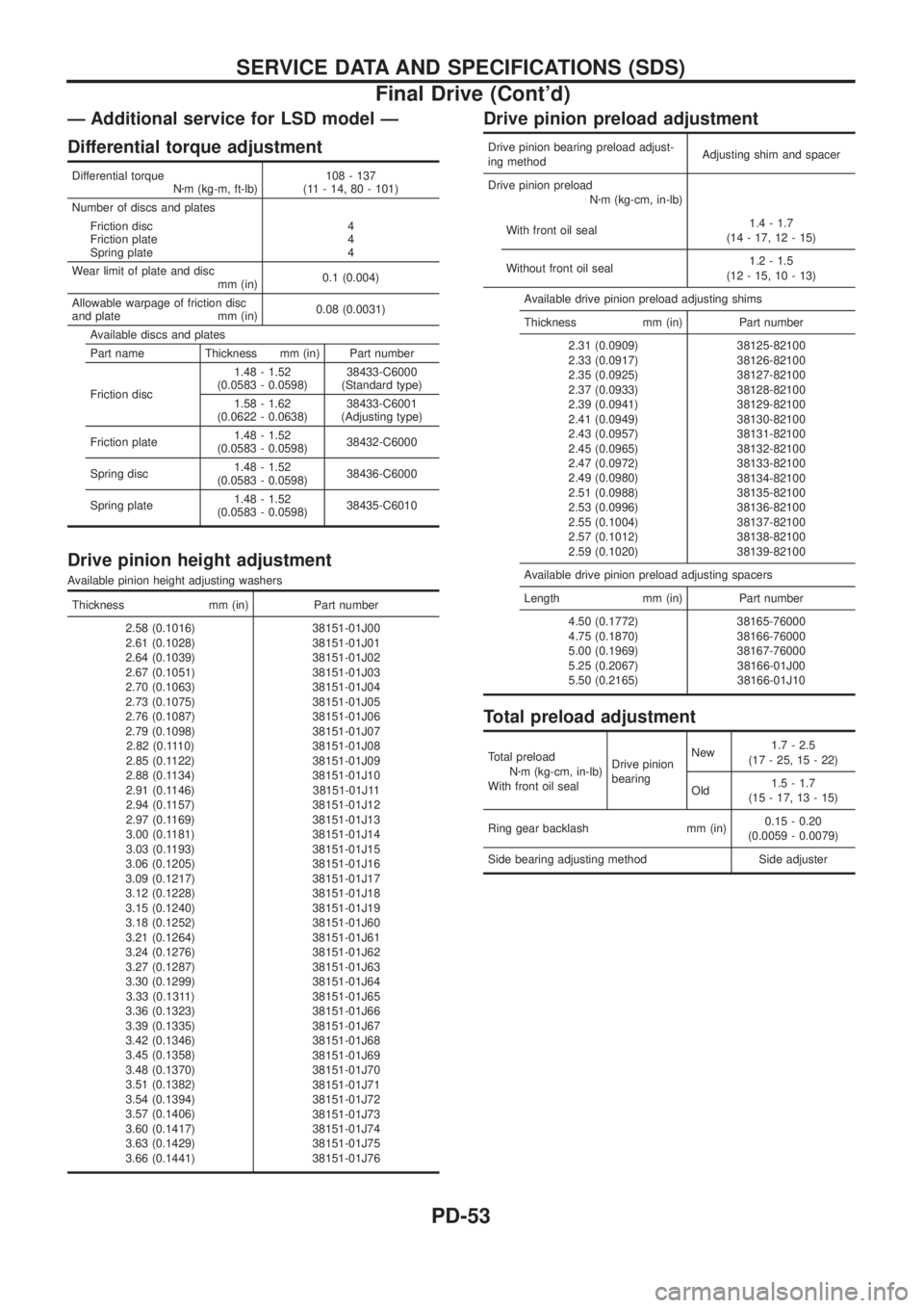
Ð Additional service for LSD model Ð
Differential torque adjustment
Differential torque
Nzm (kg-m, ft-lb)108 - 137
(11 - 14, 80 - 101)
Number of discs and plates
Friction disc
Friction plate
Spring plate4
4
4
Wear limit of plate and disc
mm (in)0.1 (0.004)
Allowable warpage of friction disc
and plate mm (in)0.08 (0.0031)
Available discs and plates
Part name Thickness mm (in) Part number
Friction disc1.48 - 1.52
(0.0583 - 0.0598)38433-C6000
(Standard type)
1.58 - 1.62
(0.0622 - 0.0638)38433-C6001
(Adjusting type)
Friction plate1.48 - 1.52
(0.0583 - 0.0598)38432-C6000
Spring disc1.48 - 1.52
(0.0583 - 0.0598)38436-C6000
Spring plate1.48 - 1.52
(0.0583 - 0.0598)38435-C6010
Drive pinion height adjustment
Available pinion height adjusting washers
Thickness mm (in) Part number
2.58 (0.1016)
2.61 (0.1028)
2.64 (0.1039)
2.67 (0.1051)
2.70 (0.1063)
2.73 (0.1075)
2.76 (0.1087)
2.79 (0.1098)
2.82 (0.1110)
2.85 (0.1122)
2.88 (0.1134)
2.91 (0.1146)
2.94 (0.1157)
2.97 (0.1169)
3.00 (0.1181)
3.03 (0.1193)
3.06 (0.1205)
3.09 (0.1217)
3.12 (0.1228)
3.15 (0.1240)
3.18 (0.1252)
3.21 (0.1264)
3.24 (0.1276)
3.27 (0.1287)
3.30 (0.1299)
3.33 (0.1311)
3.36 (0.1323)
3.39 (0.1335)
3.42 (0.1346)
3.45 (0.1358)
3.48 (0.1370)
3.51 (0.1382)
3.54 (0.1394)
3.57 (0.1406)
3.60 (0.1417)
3.63 (0.1429)
3.66 (0.1441)38151-01J00
38151-01J01
38151-01J02
38151-01J03
38151-01J04
38151-01J05
38151-01J06
38151-01J07
38151-01J08
38151-01J09
38151-01J10
38151-01J11
38151-01J12
38151-01J13
38151-01J14
38151-01J15
38151-01J16
38151-01J17
38151-01J18
38151-01J19
38151-01J60
38151-01J61
38151-01J62
38151-01J63
38151-01J64
38151-01J65
38151-01J66
38151-01J67
38151-01J68
38151-01J69
38151-01J70
38151-01J71
38151-01J72
38151-01J73
38151-01J74
38151-01J75
38151-01J76
Drive pinion preload adjustment
Drive pinion bearing preload adjust-
ing methodAdjusting shim and spacer
Drive pinion preload
Nzm (kg-cm, in-lb)
With front oil seal1.4 - 1.7
(14 - 17, 12 - 15)
Without front oil seal1.2 - 1.5
(12 - 15, 10 - 13)
Available drive pinion preload adjusting shims
Thickness mm (in) Part number
2.31 (0.0909)
2.33 (0.0917)
2.35 (0.0925)
2.37 (0.0933)
2.39 (0.0941)
2.41 (0.0949)
2.43 (0.0957)
2.45 (0.0965)
2.47 (0.0972)
2.49 (0.0980)
2.51 (0.0988)
2.53 (0.0996)
2.55 (0.1004)
2.57 (0.1012)
2.59 (0.1020)38125-82100
38126-82100
38127-82100
38128-82100
38129-82100
38130-82100
38131-82100
38132-82100
38133-82100
38134-82100
38135-82100
38136-82100
38137-82100
38138-82100
38139-82100
Available drive pinion preload adjusting spacers
Length mm (in) Part number
4.50 (0.1772)
4.75 (0.1870)
5.00 (0.1969)
5.25 (0.2067)
5.50 (0.2165)38165-76000
38166-76000
38167-76000
38166-01J00
38166-01J10
Total preload adjustment
Total preload
Nzm (kg-cm, in-lb)
With front oil sealDrive pinion
bearingNew1.7 - 2.5
(17 - 25, 15 - 22)
Old1.5 - 1.7
(15 - 17, 13 - 15)
Ring gear backlash mm (in)0.15 - 0.20
(0.0059 - 0.0079)
Side bearing adjusting method Side adjuster
SERVICE DATA AND SPECIFICATIONS (SDS)
Final Drive (Cont'd)
PD-53