Page 1124 of 1226
CAUTION:
+Before removing the seat belt pre-tensioner assembly (if equipped), turn the ignition switch off,
disconnect both battery cables and wait at least 3 minutes.
+After replacing or reinstalling seat belt pre-tensioner assembly, or reconnecting seat belt pre-ten-
sioner connector, check the system function. Refer to ``SRS Operation Check'' (RS-30) for details.
+Do not disassemble buckle or seat belt assembly.
+Replace anchor bolts if they are deformed or worn out.
+Never oil tongue and buckle.
+If any component of seat belt assembly is questionable, do not repair. Replace the whole seat belt
assembly.
+If webbing is cut, frayed, or damaged, replace seat belt assembly.
+When replacing seat belt assembly, use a genuine seat belt assembly.
+After any collision, inspect all seat belt assemblies, including retractors and other attached hard-
wares (i.e., guide rail set).
SEAT BELTS
RS-2
Page 1136 of 1226
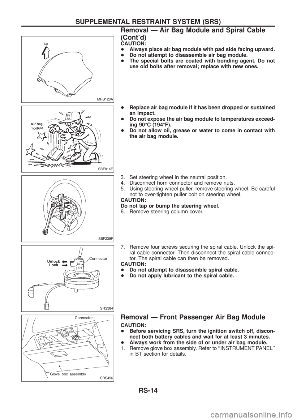
CAUTION:
+Always place air bag module with pad side facing upward.
+Do not attempt to disassemble air bag module.
+The special bolts are coated with bonding agent. Do not
use old bolts after removal; replace with new ones.
+Replace air bag module if it has been dropped or sustained
an impact.
+Do not expose the air bag module to temperatures exceed-
ing 90ÉC (194ÉF).
+Do not allow oil, grease or water to come in contact with
the air bag module.
3. Set steering wheel in the neutral position.
4. Disconnect horn connector and remove nuts.
5. Using steering wheel puller, remove steering wheel. Be careful
not to over-tighten puller bolt on steering wheel.
CAUTION:
Do not tap or bump the steering wheel.
6. Remove steering column cover.
7. Remove four screws securing the spiral cable. Unlock the spi-
ral cable connector. Then disconnect the spiral cable connec-
tor. The spiral cable can then be removed.
CAUTION:
+Do not attempt to disassemble spiral cable.
+Do not apply lubricant to the spiral cable.
Removal Ð Front Passenger Air Bag Module
CAUTION:
+Before servicing SRS, turn the ignition switch off, discon-
nect both battery cables and wait for at least 3 minutes.
+Always work from the side of or under air bag module.
1. Remove glove box assembly. Refer to ``INSTRUMENT PANEL''
in BT section for details.
MRS120A
SBF814E
SBF239F
SRS384
SRS456
SUPPLEMENTAL RESTRAINT SYSTEM (SRS)
Removal Ð Air Bag Module and Spiral Cable
(Cont'd)
RS-14
Page 1137 of 1226
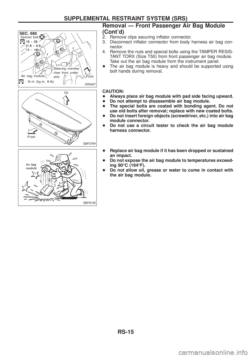
2. Remove clips securing in¯ator connector.
3. Disconnect in¯ator connector from body harness air bag con-
nector.
4. Remove the nuts and special bolts using the TAMPER RESIS-
TANT TORX (Size T50) from front passenger air bag module.
Take out the air bag module from the instrument panel.
+The air bag module is heavy and should be supported using
bolt hands during removal.
CAUTION:
+Always place air bag module with pad side facing upward.
+Do not attempt to disassemble air bag module.
+The special bolts are coated with bonding agent. Do not
use old bolts after removal; replace with new coated bolts.
+Do not insert foreign objects (screwdriver, etc.) into air bag
module connector.
+Do not use a circuit tester to check the air bag module
harness connector.
+Replace air bag module if it has been dropped or sustained
an impact.
+Do not expose the air bag module to temperatures exceed-
ing 90ÉC (194ÉF).
+Do not allow oil, grease or water to come in contact with
the air bag module.
SRS457
SBF579H
SBF814E
SUPPLEMENTAL RESTRAINT SYSTEM (SRS)
Removal Ð Front Passenger Air Bag Module
(Cont'd)
RS-15
Page 1169 of 1226
STEERING SYSTEM
SECTION
ST
CONTENTS
PRECAUTIONS AND PREPARATION............................1
Supplemental Restraint System (SRS) ``AIR
BAG'' and ``SEAT BELT PRE-TENSIONER''...............1
Precautions for Steering System .................................1
Special Service Tools ..................................................1
NOISE, VIBRATION AND HARSHNESS (NVH)
TROUBLESHOOTING.....................................................3
NVH Troubleshooting Chart.........................................3
ON-VEHICLE SERVICE..................................................4
Checking Steering Wheel Play ....................................4
Checking Neutral Position on Steering Wheel ............4
Front Wheel Turning Angle ..........................................4
Checking and Adjusting Drive Belts ............................5
Checking Fluid Level ...................................................5
Checking Fluid Leakage ..............................................5
Bleeding Hydraulic System..........................................6
Checking Steering Wheel Turning Force ....................6
Checking Hydraulic System.........................................6
STEERING WHEEL AND STEERING COLUMN............8
Removal and Installation .............................................8
Disassembly and Assembly .......................................10Inspection................................................................... 11
POWER STEERING SYSTEM (Model: PB69K)..........12
Description .................................................................12
POWER STEERING GEAR (Model: PB69K)...............13
Removal and Installation ...........................................13
Inspection...................................................................13
POWER STEERING OIL PUMP....................................15
Removal and Installation ...........................................15
Disassembly and Assembly .......................................16
Pre-disassembly Inspection .......................................16
Inspection...................................................................17
Disassembly...............................................................17
Assembly ...................................................................18
STEERING LINKAGE....................................................19
Removal and Installation ...........................................19
Disassembly...............................................................20
Inspection...................................................................20
SERVICE DATA AND SPECIFICATIONS (SDS)..........22
General Speci®cations ...............................................22
Inspection and Adjustment ........................................22
ST
Page 1171 of 1226
Tool number
Tool nameDescription
ST29020001
Ball joint remover
NT551
Removing ball joint
a: 34 mm (1.34 in)
b: 6.5 mm (0.256 in)
c: 61.5 mm (2.421 in)
ST27091000
Pressure gauge
NT547
Measuring oil pressure
KV48102500
Pressure gauge adapter
NT542
Measuring oil pressure
ST3127S000
V1GG91030000
Torque wrench
V2HT62940000
Socket adapter
V3HT62900000
Socket adapter
NT541
Measuring turning torque
KV48100301
Strut and steering gear box
attachment
NT688
Disassembling and assembling steering gear
a: 162 mm (6.38 in)
b: 110 mm (4.33 in)
c: 190 mm (7.48 in)
d: 9 mm (0.35 in)
PRECAUTIONS AND PREPARATION
Special Service Tools (Cont'd)
ST-2
Page 1174 of 1226
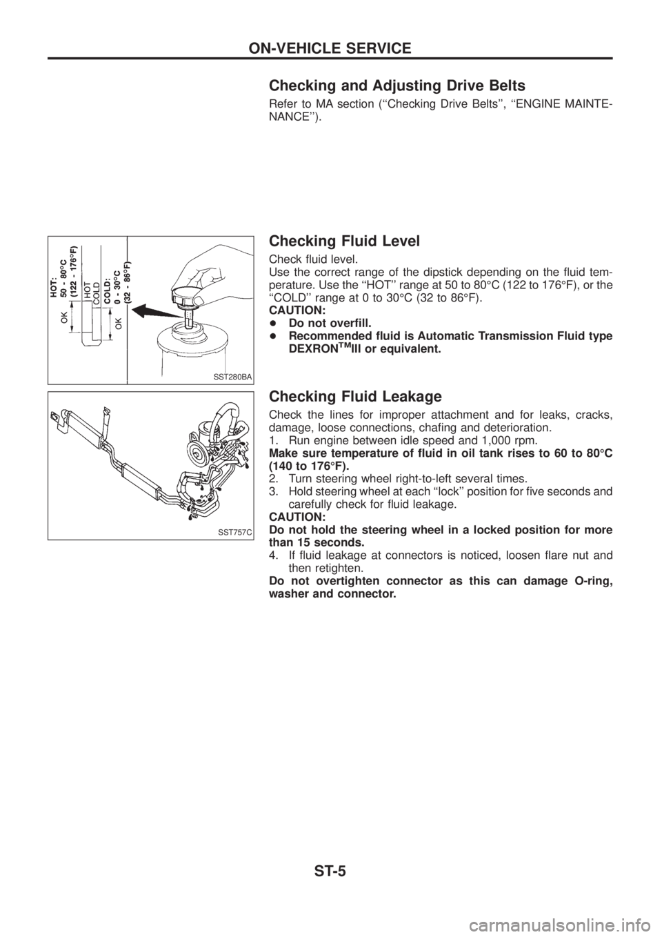
Checking and Adjusting Drive Belts
Refer to MA section (``Checking Drive Belts'', ``ENGINE MAINTE-
NANCE'').
Checking Fluid Level
Check ¯uid level.
Use the correct range of the dipstick depending on the ¯uid tem-
perature. Use the ``HOT'' range at 50 to 80ÉC (122 to 176ÉF), or the
``COLD'' range at 0 to 30ÉC (32 to 86ÉF).
CAUTION:
+Do not over®ll.
+Recommended ¯uid is Automatic Transmission Fluid type
DEXRON
TMIII or equivalent.
Checking Fluid Leakage
Check the lines for improper attachment and for leaks, cracks,
damage, loose connections, cha®ng and deterioration.
1. Run engine between idle speed and 1,000 rpm.
Make sure temperature of ¯uid in oil tank rises to 60 to 80ÉC
(140 to 176ÉF).
2. Turn steering wheel right-to-left several times.
3. Hold steering wheel at each ``lock'' position for ®ve seconds and
carefully check for ¯uid leakage.
CAUTION:
Do not hold the steering wheel in a locked position for more
than 15 seconds.
4. If ¯uid leakage at connectors is noticed, loosen ¯are nut and
then retighten.
Do not overtighten connector as this can damage O-ring,
washer and connector.
SST280BA
SST757C
ON-VEHICLE SERVICE
ST-5
Page 1175 of 1226
Bleeding Hydraulic System
1. Raise front end of vehicle until wheels are clear of the ground.
2. Add ¯uid into oil tank to speci®ed level. Then, quickly turn steer-
ing wheel fully to right and left and lightly touch steering stop-
pers.
Repeat steering wheel operation until ¯uid level no longer
decreases.
3. Start engine.
Repeat step 2 above.
+Incomplete air bleeding will cause the following to occur. When
this happens, bleed air again.
a. Air bubbles in reservoir tank
b. Clicking noise in oil pump
c. Excessive buzzing in oil pump
Fluid noise may occur in the valve or oil pump. This is common
when the vehicle is stationary or while turning steering wheel
slowly. This does not affect performance or durability of the system.
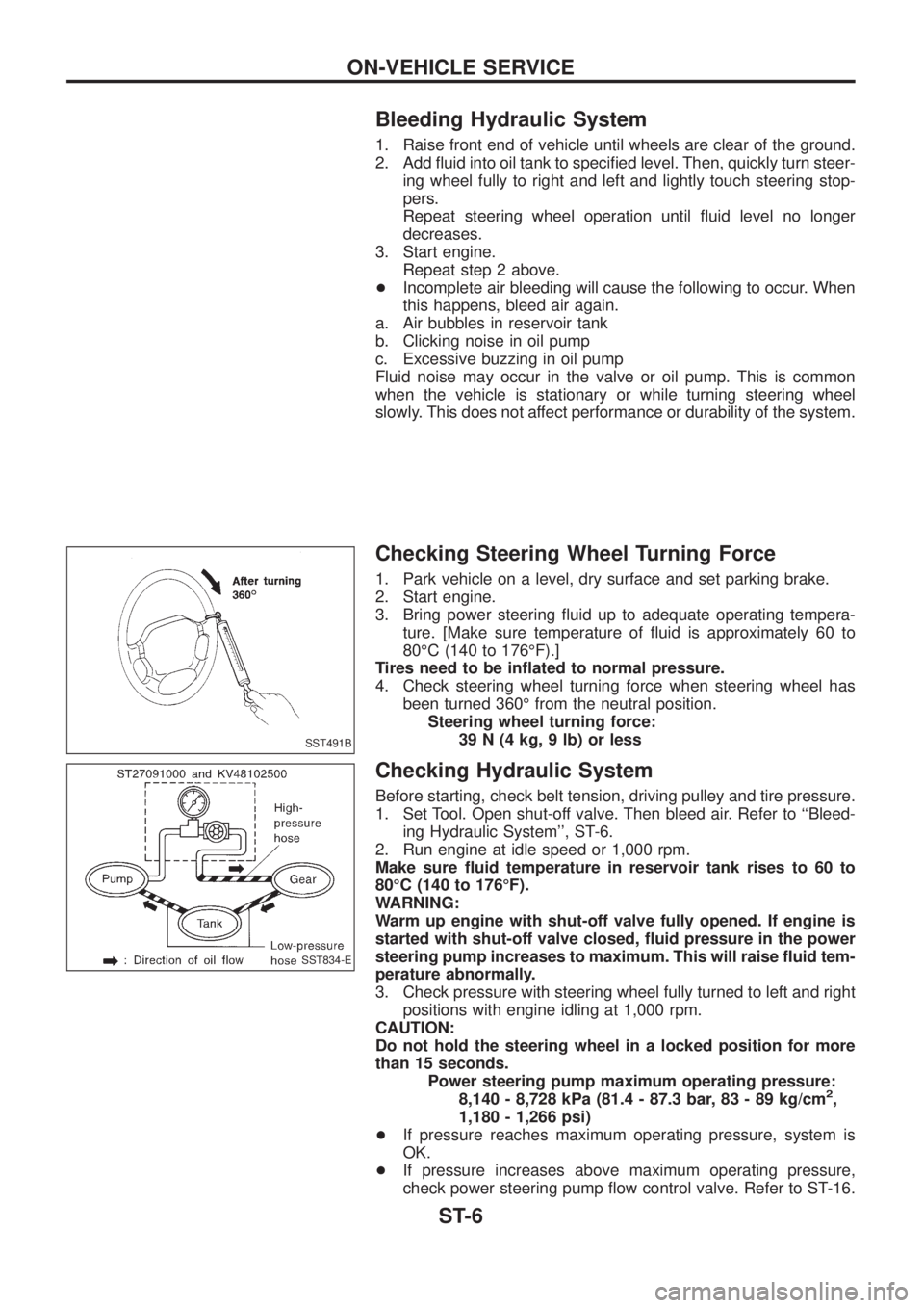
Checking Steering Wheel Turning Force
1. Park vehicle on a level, dry surface and set parking brake.
2. Start engine.
3. Bring power steering ¯uid up to adequate operating tempera-
ture. [Make sure temperature of ¯uid is approximately 60 to
80ÉC (140 to 176ÉF).]
Tires need to be in¯ated to normal pressure.
4. Check steering wheel turning force when steering wheel has
been turned 360É from the neutral position.
Steering wheel turning force:
39 N (4 kg, 9 lb) or less
Checking Hydraulic System
Before starting, check belt tension, driving pulley and tire pressure.
1. Set Tool. Open shut-off valve. Then bleed air. Refer to ``Bleed-
ing Hydraulic System'', ST-6.
2. Run engine at idle speed or 1,000 rpm.
Make sure ¯uid temperature in reservoir tank rises to 60 to
80ÉC (140 to 176ÉF).
WARNING:
Warm up engine with shut-off valve fully opened. If engine is
started with shut-off valve closed, ¯uid pressure in the power
steering pump increases to maximum. This will raise ¯uid tem-
perature abnormally.
3. Check pressure with steering wheel fully turned to left and right
positions with engine idling at 1,000 rpm.
CAUTION:
Do not hold the steering wheel in a locked position for more
than 15 seconds.
Power steering pump maximum operating pressure:
8,140 - 8,728 kPa (81.4 - 87.3 bar, 83 - 89 kg/cm
2,
1,180 - 1,266 psi)
+If pressure reaches maximum operating pressure, system is
OK.
+If pressure increases above maximum operating pressure,
check power steering pump ¯ow control valve. Refer to ST-16.
SST491B
SST834-E
ON-VEHICLE SERVICE
ST-6
Page 1182 of 1226
Removal and Installation
Before removal, clean gear housing and oil pump exteriors
using a steam cleaner. Then dry with compressed air.
+Plug openings of gear housing, and securely locate hose con-
nectors at a position higher than oil pump and cover with paper
towels.
+Be extremely careful to prevent entry of foreign matter into
hoses through connectors.
+When installing pitman arm, align four grooves of pitman arm
serrations with four projections of sector shaft serrations, and
install and tighten lock washer and nut.
Inspection
Do not disassemble for power steering gear assembly.
TURNING TORQUE MEASUREMENT
1. Measure turning torque at 360É position.
a. Install steering gear on Tool.
SST774C
SST040-A
POWER STEERING GEAR (Model: PB69K)
ST-13