Page 1096 of 1226

REAR AXLE &
REAR SUSPENSION
SECTION
RA
CONTENTS
PRECAUTIONS AND PREPARATION............................1
Precautions ..................................................................1
Special Service Tools ..................................................1
Commercial Service Tools ...........................................2
NOISE, VIBRATION AND HARSHNESS (NVH)
TROUBLESHOOTING.....................................................3
NVH Troubleshooting Chart.........................................3
REAR AXLE AND REAR SUSPENSION........................4
ON-VEHICLE SERVICE..................................................5
Rear Axle and Rear Suspension Parts .......................5
Rear Wheel Bearing ....................................................5
REAR AXLE.....................................................................6
Components.................................................................6
Removal .......................................................................7
Inspection.....................................................................9Installation ....................................................................9
REAR SUSPENSION.....................................................12
Removal and Installation ...........................................13
Coil Spring and Shock Absorber ...............................14
Upper Link, Lower Link and Panhard Rod ................14
Stabilizer Bar .............................................................15
STABILIZER RELEASE DEVICE..................................16
System Components .................................................16
System Description ....................................................16
Removal and Installation ...........................................17
Wiring Diagram ..........................................................18
Trouble Diagnoses.....................................................20
SERVICE DATA AND SPECIFICATIONS (SDS)..........25
General Speci®cations ...............................................25
Inspection and Adjustment ........................................25
RA
Page 1097 of 1226
Precautions
+When installing rubber parts, ®nal tightening must be car-
ried out under unladen condition* with tires on ground.
*: Fuel, radiator coolant and engine oil full. Spare tire, jack,
hand tools and mats in designated positions.
+Use ¯are nut wrench when removing and installing brake
tubes.
+After installing removed suspension parts, check wheel
alignment and adjust if necessary.
+Always torque brake lines when installing.
Special Service Tools
Tool number
Tool nameDescription
KV40101000
Axle stand
NT159
Removing rear axle shaft
ST36230000
Sliding hammer
NT126
Removing rear axle shaft
ST38080001
Bearing lock nut wrench
NT507
Removing wheel bearing lock nut
a: 58 mm (2.28 in)
KV40106500
Wheel bearing puller
NT724
Removing wheel bearing
GG94310000
Flare nut torque
wrench
NT406
Removing and installing brake piping
a: 10 mm (0.39 in)
SBR820BA
PRECAUTIONS AND PREPARATION
RA-1
Page 1098 of 1226
Commercial Service Tools
Tool name Description
Equivalent to GG94310000
j
1Flare nut crowfoot
j
2Torque wrench
NT360
Removing and installing each brake piping
a: 10 mm (0.39 in)
Rear axle oil seal drift
NT163
Installing oil seal
a: 74 mm (2.91 in) dia.
b: 68 mm (2.68 in) dia.
c: 10 mm (0.39 in)
PRECAUTIONS AND PREPARATION
RA-2
Page 1101 of 1226
Rear Axle and Rear Suspension Parts
Check rear axle and rear suspension parts for excessive play, wear
or damage.
+Shake each rear wheel to check for excessive play.
+Retighten all nuts and bolts to the speci®ed torque.
Tightening torque:
Refer to REAR SUSPENSION, RA-12.
+Check shock absorber for oil leakage or other damage.
+Check shock absorber bushing for excessive wear or other
damage.
Rear Wheel Bearing
+Check that wheel bearings operate smoothly.
+Check axial end play.
Axial end play:
0mm(0in)
SMA525A
SRA814A
SRA755A
ON-VEHICLE SERVICE
RA-5
Page 1103 of 1226
Removal
CAUTION:
+Before removing the rear axle, disconnect the ABS wheel
sensor from the assembly. Then move it away from the
axle. Failure to do so may result in damage to the sensor
wires and the sensor becoming inoperative.
+Wheel bearing does not require maintenance.
+If growling noise is emitted from wheel bearing during
operation, replace wheel bearing assembly.
+If the wheel bearing assembly is removed, it must be renewed.
The old assembly must not be re-used.
1. Disconnect parking brake cable and brake tube.
2. Remove nuts securing wheel bearing cage with baffle plate.
3. Draw out axle shaft with Tool.
When drawing out axle shaft, be careful not to damage oil seal.
4. Remove O-ring.
5. Remove oil seal with a screwdriver.
Do not reuse oil seal once it is removed.
Always install new one.
6. Remove ABS sensor rotor. Ð Models with ABS Ð
SRA757A
SRA845A
SRA846A
SRA799A
REAR AXLE
RA-7
Page 1106 of 1226
6. Install a new wheel bearing lock washer.
7. Tighten wheel bearing lock nut to speci®ed torque.
: 441 - 490 Nzm (45 - 50 kg-m, 325 - 362 ft-lb)
Be sure to bend bearing lock washer up.
8. Check wheel bearing preload.
a. Turn bearing cage (with respect to axle shaft) two or three
times. It must turn smoothly.
b. Attach spring gauge to bearing cage bolt (as shown at left) and
pull it at a speed of 10 rpm to measure preload.
Spring gauge indication:
8.8 - 42.2 N (0.9 - 4.3 kg, 2.0 - 9.5 lb)
9. Install new oil seal to rear axle housing using a suitable tool.
After installing new oil seal, coat sealing lip with multi-purpose
grease.
10. Install new O-ring to rear axle housing.
11. Press ABS sensor rotor onto axle shaft until it contacts wheel
bearing lock nut.
12. Install axle shafts in rear axle housing.
Be careful not to damage oil seal.
SRA828A
SRA821A
SRA850A
SRA822A
SRA823A
REAR AXLE
Installation (Cont'd)
RA-10
Page 1110 of 1226

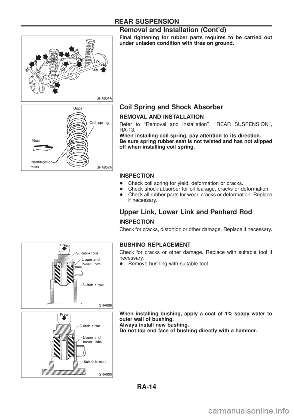
Final tightening for rubber parts requires to be carried out
under unladen condition with tires on ground.
Coil Spring and Shock Absorber
REMOVAL AND INSTALLATION
Refer to ``Removal and Installation'', ``REAR SUSPENSION'',
RA-13.
When installing coil spring, pay attention to its direction.
Be sure spring rubber seat is not twisted and has not slipped
off when installing coil spring.
INSPECTION
+Check coil spring for yield, deformation or cracks.
+Check shock absorber for oil leakage, cracks or deformation.
+Check all rubber parts for wear, cracks or deformation. Replace
if necessary.
Upper Link, Lower Link and Panhard Rod
INSPECTION
Check for cracks, distortion or other damage. Replace if necessary.
BUSHING REPLACEMENT
Check for cracks or other damage. Replace with suitable tool if
necessary.
+Remove bushing with suitable tool.
When installing bushing, apply a coat of 1% soapy water to
outer wall of bushing.
Always install new bushing.
Do not tap end face of bushing directly with a hammer.
SRA851A
SRA852A
SRA898
SRA900
REAR SUSPENSION
Removal and Installation (Cont'd)
RA-14
Page 1121 of 1226
General Speci®cations
Suspension type 5-link type rigid with coil spring
Shock absorber type Double-acting hydraulic
Stabilizer Standard equipment
Inspection and Adjustment
WHEEL BEARING
Total end play mm (in) 0 (0)
Wheel bearing preload at bearing
cage bolt N (kg, lb)8.8 - 42.2 (0.9 - 4.3, 2.0 - 9.5)
SERVICE DATA AND SPECIFICATIONS (SDS)
RA-25