Page 997 of 1226
Checking Exhaust System
Check exhaust pipes, muffler and mounting for improper
attachment, leaks, cracks, damage, loose connections, cha®ng and
deterioration.
Checking Clutch Fluid Level and Leaks
If ¯uid level is extremely low, check clutch system for leaks.
Checking Clutch System
Check ¯uid lines and operating cylinder for improper attachment,
cracks, damage, loose connections, cha®ng and deterioration.
Checking M/T Oil Level and Leaks
Never start engine while checking oil level.
1. Check manual transmission for leakage.
2. Check oil level.
Filler plug:
:25-34Nzm (2.5 - 3.5 kg-m, 18 - 25 ft-lb)
Changing M/T Oil
Oil grade:
API GL-4. Refer to ``RECOMMENDED FLUIDS AND
LUBRICANTS'', MA-9.
Oil capacity:
FS5R50B 3.8 liters (6-3/4 Imp pt)
Re®ll 2.9 liters (5-1/8 Imp pt)
FS5R30A 5.1 liters (9 Imp pt)
Drain plug:
:25-34Nzm (2.5 - 3.5 kg-m, 18 - 25 ft-lb)
SMA211A
SMA991C
SMA992C
SMA103
SMA255A
CHASSIS AND BODY MAINTENANCE
MA-20
Page 999 of 1226

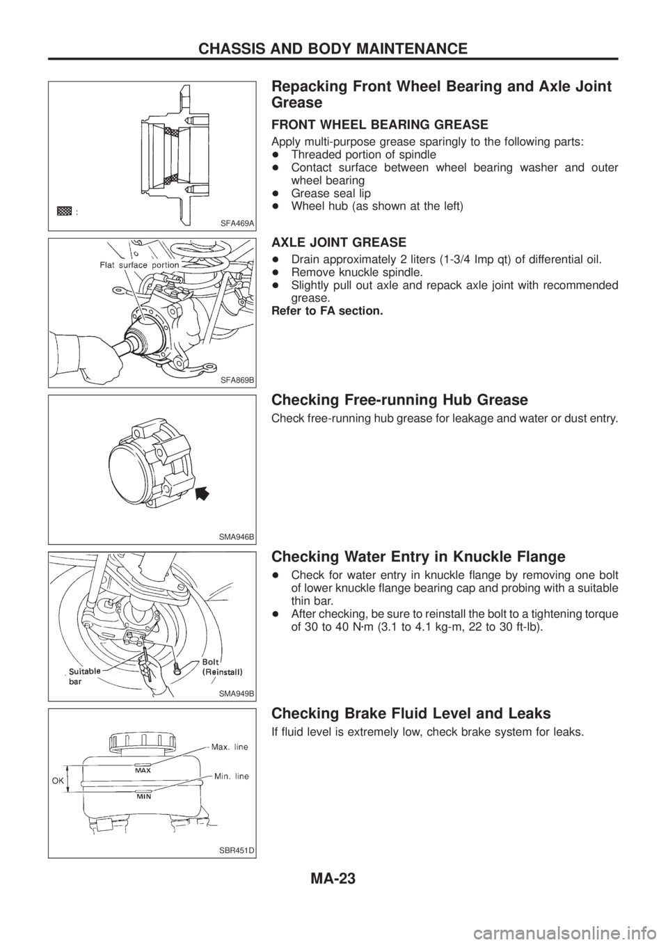
Checking Differential Gear Oil
1. Check differential carrier for oil leakage.
2. Check oil level.Filler plug:
:59-98N zm (6 - 10 kg-m, 43 - 72 ft-lb)
Changing Differential Gear Oil
Oil capacity:
Front5.4 liters (9-1/2 Imp pt)
Rear H233B (Without diff. lock) 2.4 liters(4-1/4 Imppt)
H233B (With diff. lock) 3.0 liters (5-1/4 Imp pt)
H260 (Without diff. lock) 4.7 liters (8-1/4 Imp pt)
H260 (With diff. lock) 3.7 liters (6-1/2 Imp pt)
Drain plug:
:59-98N zm (6 - 10 kg-m, 43 - 72 ft-lb)
Limited-slip differential gear
+ Use only approved or recommended limited-slip differential
gear oil.
+ Limited-slip differential identi®cation.
(1) Lift both rear wheels off the ground.
(2) Turn one rear wheel by hand.
(3) If both rear wheels turn in the same direction simultaneously, vehicle is equipped with limited-slip differential.
Checking Front Wheel Bearing Grease
+Check that wheel bearings operate smoothly.
+ Check front wheel bearings for grease leakage and water or
dust entry.
+ Replace front wheel bearings or front wheel bearing grease if
wheel bearings do not turn smoothly.
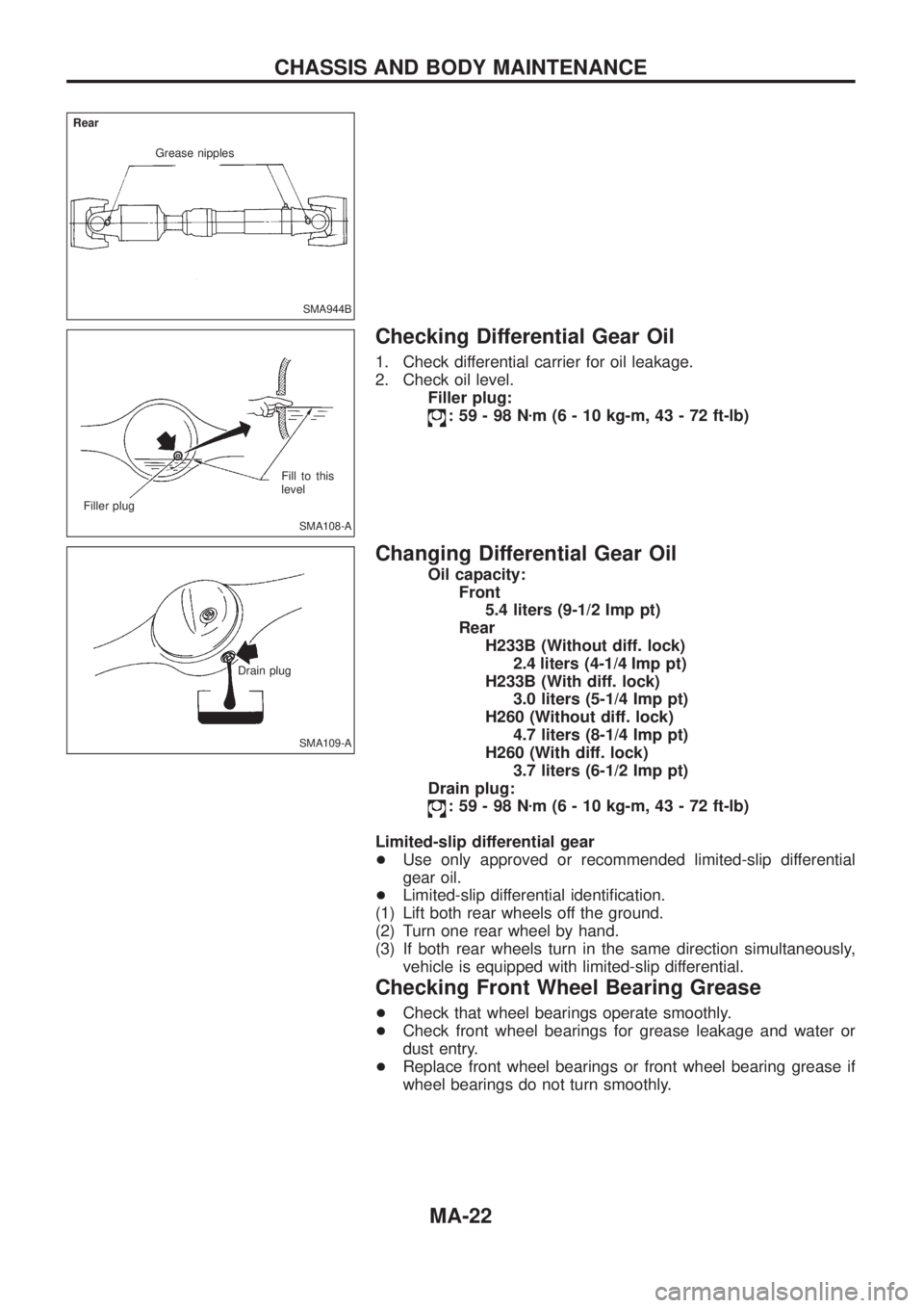
SMA944B
Grease nipples
Rear
SMA108-A
Filler plug
Fill to this
level
SMA109-A
Drain plug
CHASSIS AND BODY MAINTENANCE
MA-22
Page 1000 of 1226

Repacking Front Wheel Bearing and Axle Joint
Grease
FRONT WHEEL BEARING GREASE
Apply multi-purpose grease sparingly to the following parts:
+Threaded portion of spindle
+Contact surface between wheel bearing washer and outer
wheel bearing
+Grease seal lip
+Wheel hub (as shown at the left)
AXLE JOINT GREASE
+Drain approximately 2 liters (1-3/4 Imp qt) of differential oil.
+Remove knuckle spindle.
+Slightly pull out axle and repack axle joint with recommended
grease.
Refer to FA section.
Checking Free-running Hub Grease
Check free-running hub grease for leakage and water or dust entry.
Checking Water Entry in Knuckle Flange
+Check for water entry in knuckle ¯ange by removing one bolt
of lower knuckle ¯ange bearing cap and probing with a suitable
thin bar.
+After checking, be sure to reinstall the bolt to a tightening torque
of 30 to 40 Nzm (3.1 to 4.1 kg-m, 22 to 30 ft-lb).
Checking Brake Fluid Level and Leaks
If ¯uid level is extremely low, check brake system for leaks.
SFA469A
SFA869B
SMA946B
SMA949B
SBR451D
CHASSIS AND BODY MAINTENANCE
MA-23
Page 1003 of 1226
Checking Power Steering Fluid and Lines
+Check ¯uid level with engine off.
+Check ¯uid level with dipstick on reservoir cap. Use ``HOT''
range at ¯uid temperatures of 50 to 80ÉC (122 to 176ÉF). Use
``COLD'' range at ¯uid temperatures of 0 to 30ÉC (32 to 86ÉF).
CAUTION:
+Do not over®ll.
+Recommended ¯uid is Automatic Transmission Fluid type
``DEXRON
TMIII'' or equivalent.
+Check lines for improper attachment, leaks, cracks, damage,
loose connections, cha®ng or deterioration.
+Check rack boots for accumulation of power steering ¯uid.
Checking Steering Damper
Check steering damper for damage and oil leakage.
Checking Steering Gear Box and Linkage
STEERING GEAR
+Check gear housing and boots for looseness, damage or
grease leakage.
+Check connection with steering column for looseness.
STEERING LINKAGE
+Check ball joint, dust cover and other component parts for
looseness, wear, damage or grease leakage.
SST280B
SST757C
SMA938A
CHASSIS AND BODY MAINTENANCE
MA-26
Page 1006 of 1226
Engine Maintenance
INSPECTION AND ADJUSTMENT
Drive belt de¯ection
Unit: mm (in)
Drive beltsUsed belt de¯ection
De¯ection of
new belt
LimitDe¯ection
after adjust-
ment
Alternator
With air condi-
tioner compressor17 (0.67)12-14
(0.47 - 0.55)9-11
(0.35 - 0.43)
Without air condi-
tioner compressor11 (0.43)7-9
(0.28 - 0.35)6-8
(0.24 - 0.31)
Power steering oil
pump14 (0.55)10-12
(0.39 - 0.47)9-11
(0.35 - 0.43)
Applied pushing force 98 N (10 kg, 22 lb)
Engine oil capacity (Re®ll capacity)
Unit:!(Imp qt)
With oil ®lter change 6.4 (5-5/8)
Without oil ®lter change 5.8 (5-1/8)
Coolant capacity (Re®ll capacity)
With reservoir tank
Unit:!(Imp qt)
With rear heater Without rear heater
RHD 12.9 (11-3/8) 11.8 (10-3/8)
LHD 12.7 (11-1/8) 11.6 (10-1/4)
Reservoir tank 2.4 (2-1/8)
Chassis and Body Maintenance
INSPECTION AND ADJUSTMENT
Wheel balance
Maximum allowable
unbalanceDynamic
(At rim ¯ange)
g (oz)10 (0.35) (one side)
Static g (oz) 20 (0.71)
SERVICE DATA AND SPECIFICATIONS (SDS)
MA-29
Page 1007 of 1226

MANUAL TRANSMISSION
SECTION
MT
CONTENTS
PREPARATION................................................................1
Special Service Tools ..................................................1
Commercial Service Tools ...........................................2
NOISE, VIBRATION AND HARSHNESS (NVH)
TROUBLESHOOTING.....................................................3
NVH Troubleshooting Chart.........................................3
ON-VEHICLE SERVICE..................................................4
Replacing Rear Oil Seal ..............................................4
Position Switch Check .................................................4
REMOVAL AND INSTALLATION....................................5
Removal .......................................................................5
Installation ....................................................................6
DESCRIPTION.................................................................7
Cross-sectional View ...................................................7
AIR BREATHER..............................................................8
Air Breather Piping ......................................................8
MAJOR OVERHAUL.......................................................9Case Components .......................................................9
Gear Components .....................................................10
Shift Control Components .........................................12
DISASSEMBLY..............................................................13
Case Components .....................................................13
Shift Control Components .........................................14
Gear Components .....................................................15
INSPECTION..................................................................19
Shift Control Components .........................................19
Gear Components .....................................................19
ASSEMBLY....................................................................21
Gear Components .....................................................21
Shift Control Components .........................................29
Case Components .....................................................29
SERVICE DATA AND SPECIFICATIONS (SDS)..........32
General Speci®cations ...............................................32
Inspection and Adjustment ........................................33
MT
Page 1008 of 1226

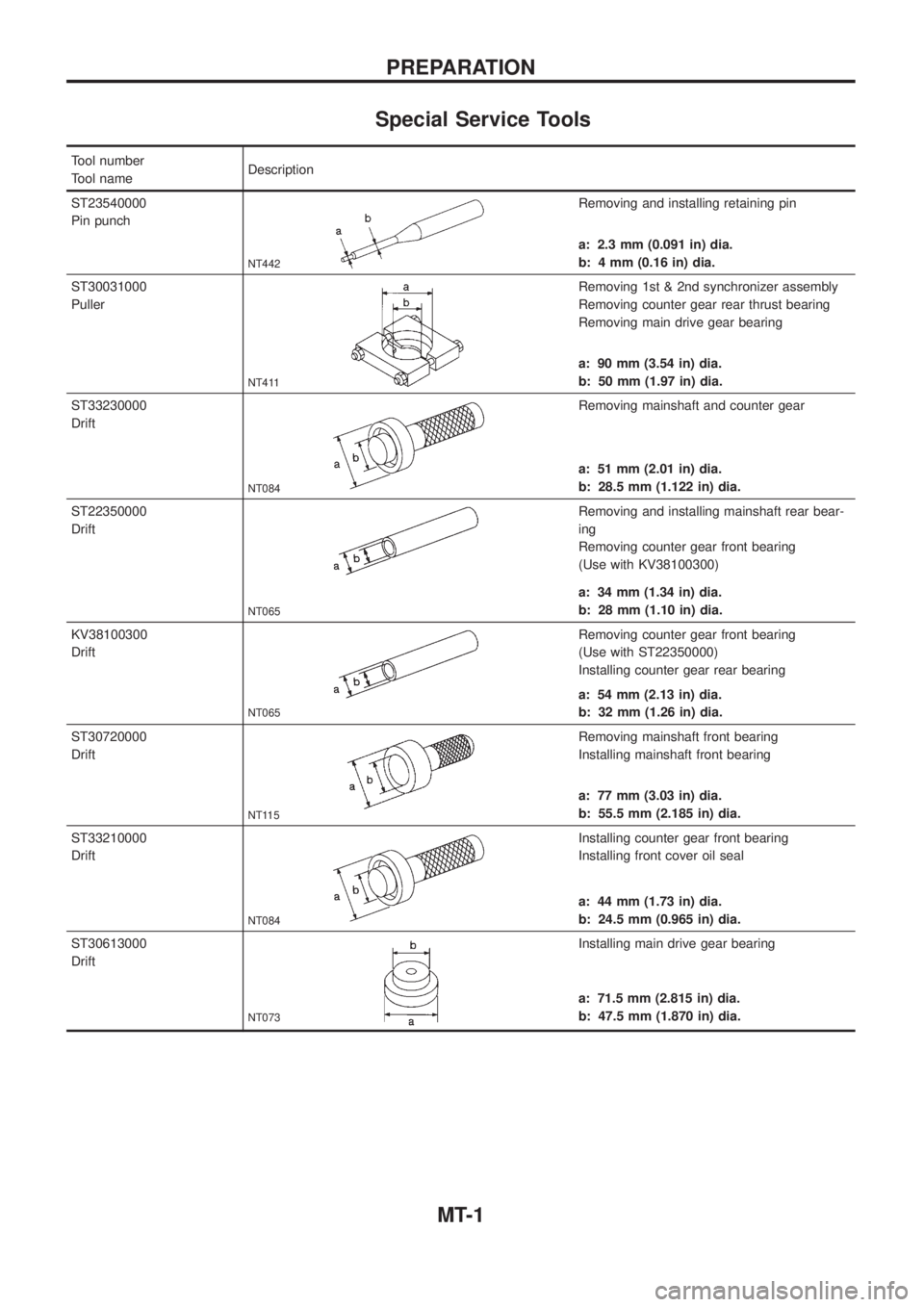
Special Service Tools
Tool number
Tool nameDescription
ST23540000
Pin punch
NT442
Removing and installing retaining pin
a: 2.3 mm (0.091 in) dia.
b: 4 mm (0.16 in) dia.
ST30031000
Puller
NT411
Removing 1st & 2nd synchronizer assembly
Removing counter gear rear thrust bearing
Removing main drive gear bearing
a: 90 mm (3.54 in) dia.
b: 50 mm (1.97 in) dia.
ST33230000
Drift
NT084
Removing mainshaft and counter gear
a: 51 mm (2.01 in) dia.
b: 28.5 mm (1.122 in) dia.
ST22350000
Drift
NT065
Removing and installing mainshaft rear bear-
ing
Removing counter gear front bearing
(Use with KV38100300)
a: 34 mm (1.34 in) dia.
b: 28 mm (1.10 in) dia.
KV38100300
Drift
NT065
Removing counter gear front bearing
(Use with ST22350000)
Installing counter gear rear bearing
a: 54 mm (2.13 in) dia.
b: 32 mm (1.26 in) dia.
ST30720000
Drift
NT115
Removing mainshaft front bearing
Installing mainshaft front bearing
a: 77 mm (3.03 in) dia.
b: 55.5 mm (2.185 in) dia.
ST33210000
Drift
NT084
Installing counter gear front bearing
Installing front cover oil seal
a: 44 mm (1.73 in) dia.
b: 24.5 mm (0.965 in) dia.
ST30613000
Drift
NT073
Installing main drive gear bearing
a: 71.5 mm (2.815 in) dia.
b: 47.5 mm (1.870 in) dia.
PREPARATION
MT-1
Page 1010 of 1226
NVH Troubleshooting Chart
Use the chart below to help you ®nd the cause of the symptom. The numbers indicate the order of the inspec-
tion. If necessary, repair or replace these parts.
Reference page
FS5R30A
Refer to MA section (``Checking M/T Oil'',
``CHASSIS AND BODY MAINTENANCE'').
MT-9
MT-9
MT-12
MT-12
MT-10
MT-10
MT-10
MT-10
SUSPECTED PARTS (Possible cause)
Transmission model
OIL (Level low)
OIL (Wrong)
OIL (Level too high)
LIQUID GASKET (Damaged)
OIL SEAL (Worn or damaged)
CHECK PLUG RETURN SPRING AND
CHECK BALL (Worn or damaged)
SHIFT FORK (Worn)
GEAR (Worn or damaged)
BEARING (Worn or damaged)
BAULK RING (Worn or damaged)
INSERT SPRING (Damaged)
SymptomNoise 1 2 3 3
Oil leakage3122
Hard to shift or will not shift 1 1 2 2
Jumps out of gear 1 2 2
NOISE, VIBRATION AND HARSHNESS (NVH)
TROUBLESHOOTING
MT-3