2006 NISSAN PATROL oil
[x] Cancel search: oilPage 963 of 1226
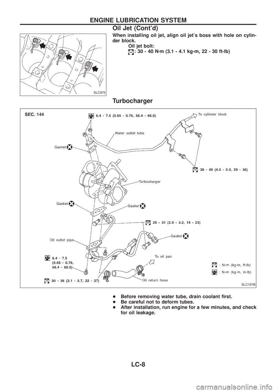
When installing oil jet, align oil jet's boss with hole on cylin-
der block.
Oil jet bolt:
:30-40Nzm (3.1 - 4.1 kg-m, 22 - 30 ft-lb)
Turbocharger
+Before removing water tube, drain coolant ®rst.
+Be careful not to deform tubes.
+After installation, run engine for a few minutes, and check
for oil leakage.
SLC975
SLC197B
ENGINE LUBRICATION SYSTEM
Oil Jet (Cont'd)
LC-8
Page 970 of 1226
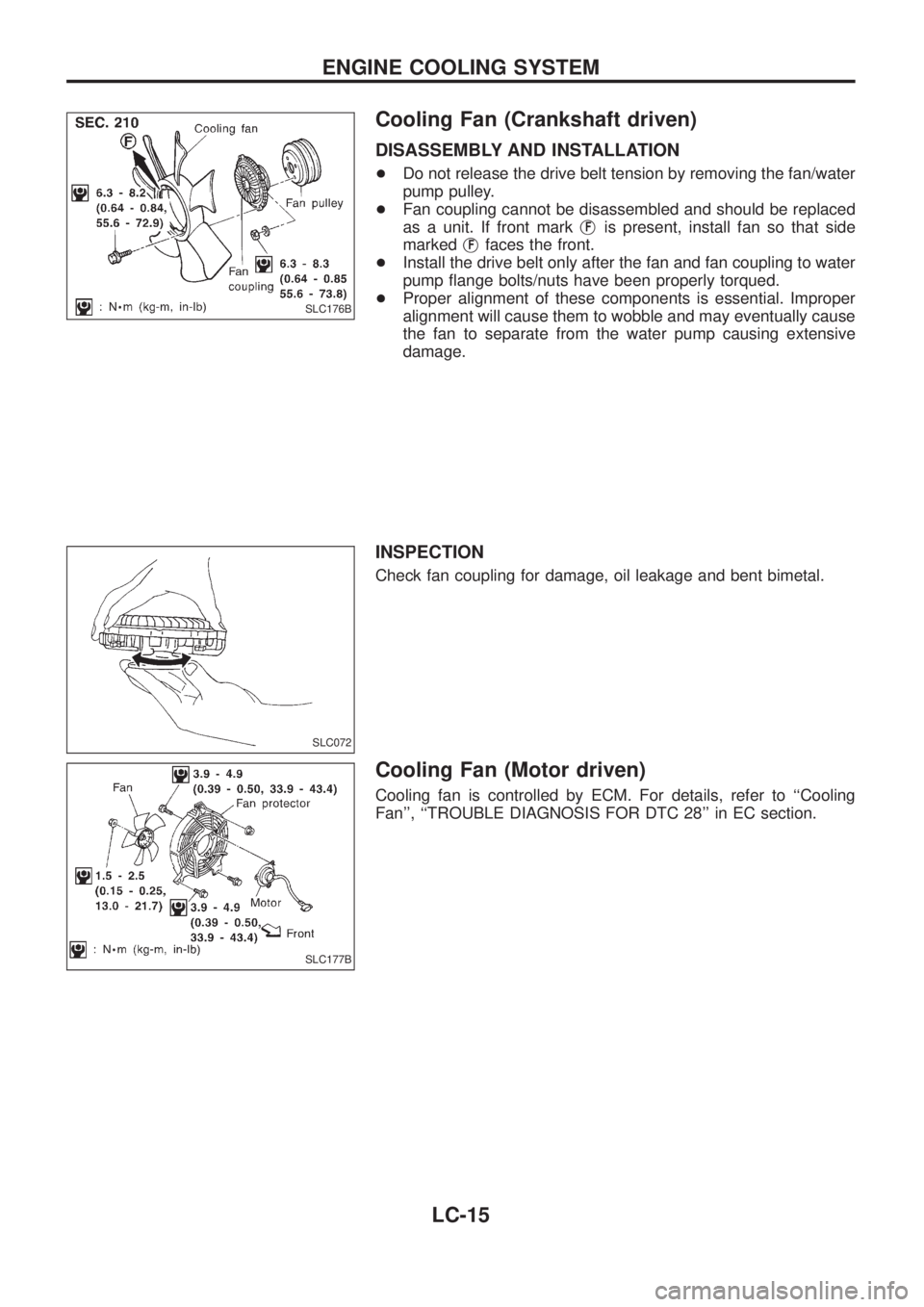
Cooling Fan (Crankshaft driven)
DISASSEMBLY AND INSTALLATION
+Do not release the drive belt tension by removing the fan/water
pump pulley.
+Fan coupling cannot be disassembled and should be replaced
as a unit. If front markj
Fis present, install fan so that side
markedj
Ffaces the front.
+Install the drive belt only after the fan and fan coupling to water
pump ¯ange bolts/nuts have been properly torqued.
+Proper alignment of these components is essential. Improper
alignment will cause them to wobble and may eventually cause
the fan to separate from the water pump causing extensive
damage.
INSPECTION
Check fan coupling for damage, oil leakage and bent bimetal.
Cooling Fan (Motor driven)
Cooling fan is controlled by ECM. For details, refer to ``Cooling
Fan'', ``TROUBLE DIAGNOSIS FOR DTC 28'' in EC section.
SLC176B
SLC072
SLC177B
ENGINE COOLING SYSTEM
LC-15
Page 972 of 1226
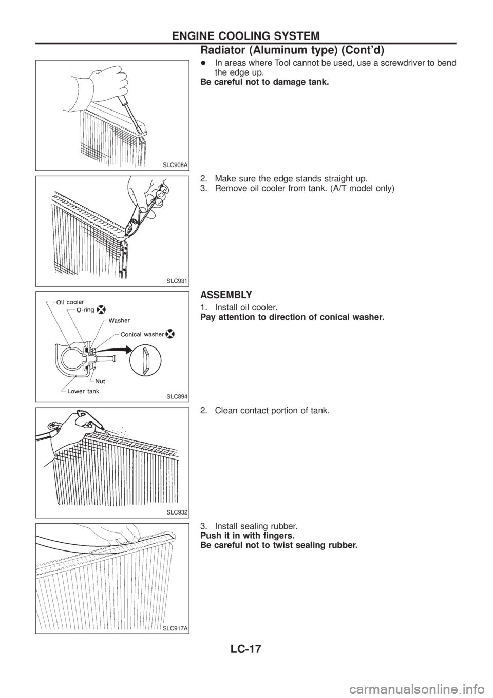
+In areas where Tool cannot be used, use a screwdriver to bend
the edge up.
Be careful not to damage tank.
2. Make sure the edge stands straight up.
3. Remove oil cooler from tank. (A/T model only)
ASSEMBLY
1. Install oil cooler.
Pay attention to direction of conical washer.
2. Clean contact portion of tank.
3. Install sealing rubber.
Push it in with ®ngers.
Be careful not to twist sealing rubber.
SLC908A
SLC931
SLC894
SLC932
SLC917A
ENGINE COOLING SYSTEM
Radiator (Aluminum type) (Cont'd)
LC-17
Page 974 of 1226
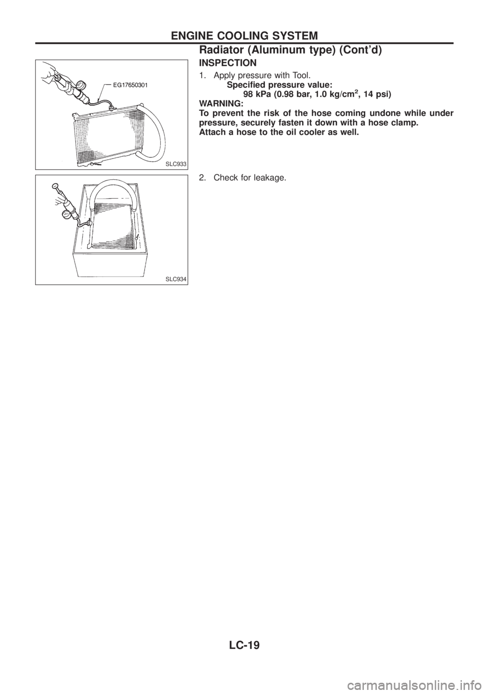
INSPECTION
1. Apply pressure with Tool.
Speci®ed pressure value:
98 kPa (0.98 bar, 1.0 kg/cm
2, 14 psi)
WARNING:
To prevent the risk of the hose coming undone while under
pressure, securely fasten it down with a hose clamp.
Attach a hose to the oil cooler as well.
2. Check for leakage.
SLC933
SLC934
ENGINE COOLING SYSTEM
Radiator (Aluminum type) (Cont'd)
LC-19
Page 976 of 1226
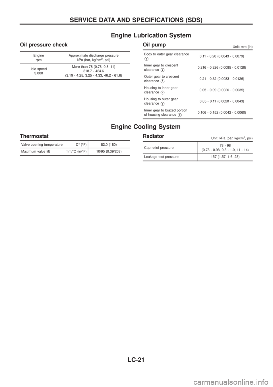
Engine Lubrication System
Oil pressure check
Engine
rpmApproximate discharge pressure
kPa (bar, kg/cm2, psi)
Idle speed
3,000More than 78 (0.78, 0.8, 11)
318.7 - 424.6
(3.19 - 4.25, 3.25 - 4.33, 46.2 - 61.6)
Oil pumpUnit: mm (in)
Body to outer gear clearance
V10.11 - 0.20 (0.0043 - 0.0079)
Inner gear to crescent
clearance
V20.216 - 0.326 (0.0085 - 0.0128)
Outer gear to crescent
clearance
V30.21 - 0.32 (0.0083 - 0.0126)
Housing to inner gear
clearance
V40.05 - 0.09 (0.0020 - 0.0035)
Housing to outer gear
clearance
V50.05 - 0.11 (0.0020 - 0.0043)
Inner gear to brazed portion
of housing clearance
V60.106 - 0.152 (0.0042 - 0.0060)
Engine Cooling System
Thermostat
Valve opening temperature CÉ (ÉF) 82.0 (180)
Maximum valve lift mm/ÉC (in/ÉF) 10/95 (0.39/203)
RadiatorUnit: kPa (bar, kg/cm2, psi)
Cap relief pressure78-98
(0.78 - 0.98, 0.8 - 1.0, 11 - 14)
Leakage test pressure 157 (1.57, 1.6, 23)
SERVICE DATA AND SPECIFICATIONS (SDS)
LC-21
Page 977 of 1226
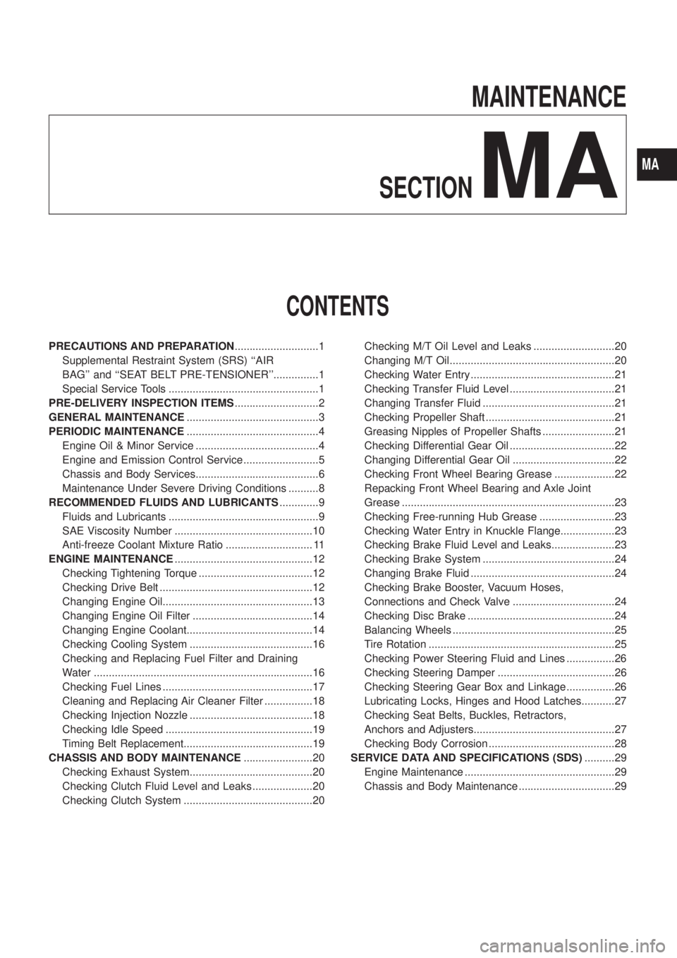
MAINTENANCE
SECTION
MA
CONTENTS
PRECAUTIONS AND PREPARATION............................1
Supplemental Restraint System (SRS) ``AIR
BAG'' and ``SEAT BELT PRE-TENSIONER''...............1
Special Service Tools ..................................................1
PRE-DELIVERY INSPECTION ITEMS............................2
GENERAL MAINTENANCE............................................3
PERIODIC MAINTENANCE............................................4
Engine Oil & Minor Service .........................................4
Engine and Emission Control Service .........................5
Chassis and Body Services.........................................6
Maintenance Under Severe Driving Conditions ..........8
RECOMMENDED FLUIDS AND LUBRICANTS.............9
Fluids and Lubricants ..................................................9
SAE Viscosity Number ..............................................10
Anti-freeze Coolant Mixture Ratio ............................. 11
ENGINE MAINTENANCE..............................................12
Checking Tightening Torque ......................................12
Checking Drive Belt ...................................................12
Changing Engine Oil..................................................13
Changing Engine Oil Filter ........................................14
Changing Engine Coolant..........................................14
Checking Cooling System .........................................16
Checking and Replacing Fuel Filter and Draining
Water .........................................................................16
Checking Fuel Lines ..................................................17
Cleaning and Replacing Air Cleaner Filter ................18
Checking Injection Nozzle .........................................18
Checking Idle Speed .................................................19
Timing Belt Replacement...........................................19
CHASSIS AND BODY MAINTENANCE.......................20
Checking Exhaust System.........................................20
Checking Clutch Fluid Level and Leaks ....................20
Checking Clutch System ...........................................20Checking M/T Oil Level and Leaks ...........................20
Changing M/T Oil.......................................................20
Checking Water Entry ................................................21
Checking Transfer Fluid Level ...................................21
Changing Transfer Fluid ............................................21
Checking Propeller Shaft ...........................................21
Greasing Nipples of Propeller Shafts ........................21
Checking Differential Gear Oil ...................................22
Changing Differential Gear Oil ..................................22
Checking Front Wheel Bearing Grease ....................22
Repacking Front Wheel Bearing and Axle Joint
Grease .......................................................................23
Checking Free-running Hub Grease .........................23
Checking Water Entry in Knuckle Flange..................23
Checking Brake Fluid Level and Leaks.....................23
Checking Brake System ............................................24
Changing Brake Fluid ................................................24
Checking Brake Booster, Vacuum Hoses,
Connections and Check Valve ..................................24
Checking Disc Brake .................................................24
Balancing Wheels ......................................................25
Tire Rotation ..............................................................25
Checking Power Steering Fluid and Lines ................26
Checking Steering Damper .......................................26
Checking Steering Gear Box and Linkage ................26
Lubricating Locks, Hinges and Hood Latches...........27
Checking Seat Belts, Buckles, Retractors,
Anchors and Adjusters...............................................27
Checking Body Corrosion ..........................................28
SERVICE DATA AND SPECIFICATIONS (SDS)..........29
Engine Maintenance ..................................................29
Chassis and Body Maintenance ................................29
MA
Page 978 of 1226
Supplemental Restraint System (SRS) ``AIR
BAG'' and ``SEAT BELT PRE-TENSIONER''
The Supplemental Restraint System such as ``AIR BAG'' and ``SEAT BELT PRE-TENSIONER'' used along with
a seat belt, helps to reduce the risk or severity of injury to the driver and front passenger in a frontal collision.
The SRS composition which is available to NISSAN MODEL Y61 is as follows (The composition varies
according to the destination.):
Driver air bag module (located in the center of the steering wheel), front passenger air bag module (located
on the instrument panel on passenger side), seat belt pre-tensioner, a diagnosis sensor unit, warning lamp,
wiring harness and spiral cable.
WARNING:
+To avoid rendering the SRS inoperative, which could increase the risk of personal injury or death
in the event of a collision which would result in air bag in¯ation, all maintenance must be performed
by an authorized NISSAN dealer.
+Improper maintenance, including incorrect removal and installation of the SRS, can lead to per-
sonal injury caused by unintentional activation of the system.
+Do not use electrical test equipment on any circuit related to the SRS unless instructed to in this
Service Manual. Spiral cable and wiring harnesses covered with yellow insulation either just before
the harness connectors or for the complete harness are related to the SRS.
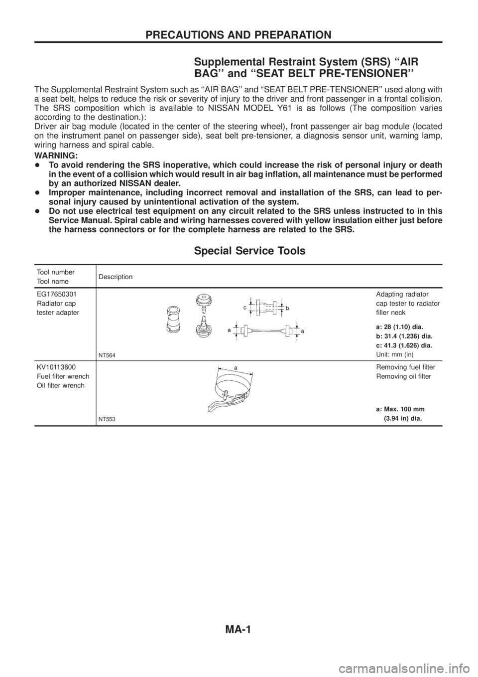
Special Service Tools
Tool number
Tool nameDescription
EG17650301
Radiator cap
tester adapter
NT564
Adapting radiator
cap tester to radiator
®ller neck
a: 28 (1.10) dia.
b: 31.4 (1.236) dia.
c: 41.3 (1.626) dia.
Unit: mm (in)
KV10113600
Fuel ®lter wrench
Oil ®lter wrench
NT553
Removing fuel ®lter
Removing oil ®lter
a: Max. 100 mm
(3.94 in) dia.
PRECAUTIONS AND PREPARATION
MA-1
Page 979 of 1226
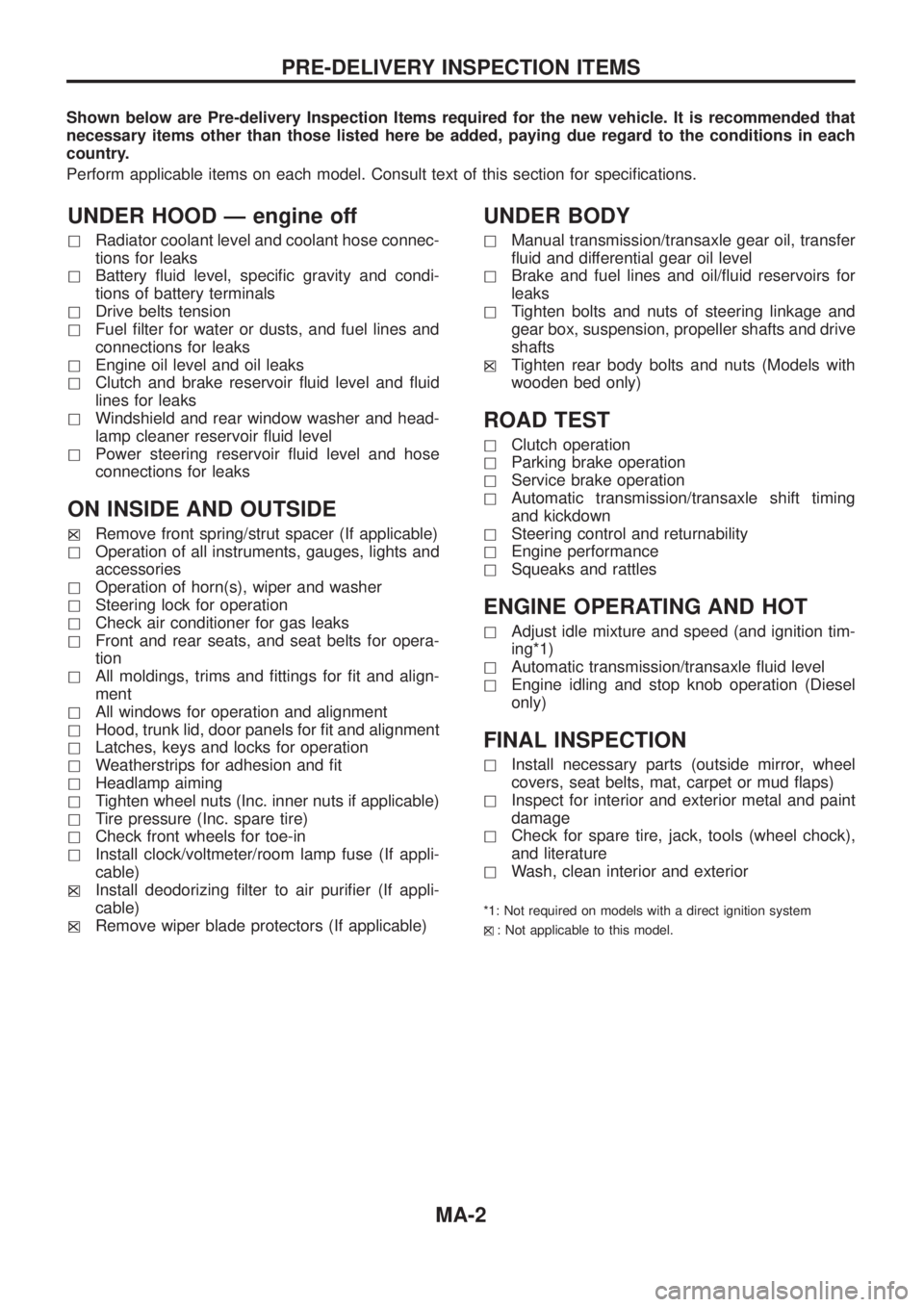
Shown below are Pre-delivery Inspection Items required for the new vehicle. It is recommended that
necessary items other than those listed here be added, paying due regard to the conditions in each
country.
Perform applicable items on each model. Consult text of this section for speci®cations.
UNDER HOOD Ð engine off
hRadiator coolant level and coolant hose connec-
tions for leaks
hBattery ¯uid level, speci®c gravity and condi-
tions of battery terminals
hDrive belts tension
hFuel ®lter for water or dusts, and fuel lines and
connections for leaks
hEngine oil level and oil leaks
hClutch and brake reservoir ¯uid level and ¯uid
lines for leaks
hWindshield and rear window washer and head-
lamp cleaner reservoir ¯uid level
hPower steering reservoir ¯uid level and hose
connections for leaks
ON INSIDE AND OUTSIDE
hXRemove front spring/strut spacer (If applicable)
hOperation of all instruments, gauges, lights and
accessories
hOperation of horn(s), wiper and washer
hSteering lock for operation
hCheck air conditioner for gas leaks
hFront and rear seats, and seat belts for opera-
tion
hAll moldings, trims and ®ttings for ®t and align-
ment
hAll windows for operation and alignment
hHood, trunk lid, door panels for ®t and alignment
hLatches, keys and locks for operation
hWeatherstrips for adhesion and ®t
hHeadlamp aiming
hTighten wheel nuts (Inc. inner nuts if applicable)
hTire pressure (Inc. spare tire)
hCheck front wheels for toe-in
hInstall clock/voltmeter/room lamp fuse (If appli-
cable)
h
XInstall deodorizing ®lter to air puri®er (If appli-
cable)
h
XRemove wiper blade protectors (If applicable)
UNDER BODY
hManual transmission/transaxle gear oil, transfer
¯uid and differential gear oil level
hBrake and fuel lines and oil/¯uid reservoirs for
leaks
hTighten bolts and nuts of steering linkage and
gear box, suspension, propeller shafts and drive
shafts
h
XTighten rear body bolts and nuts (Models with
wooden bed only)
ROAD TEST
hClutch operation
hParking brake operation
hService brake operation
hAutomatic transmission/transaxle shift timing
and kickdown
hSteering control and returnability
hEngine performance
hSqueaks and rattles
ENGINE OPERATING AND HOT
hAdjust idle mixture and speed (and ignition tim-
ing*1)
hAutomatic transmission/transaxle ¯uid level
hEngine idling and stop knob operation (Diesel
only)
FINAL INSPECTION
hInstall necessary parts (outside mirror, wheel
covers, seat belts, mat, carpet or mud ¯aps)
hInspect for interior and exterior metal and paint
damage
hCheck for spare tire, jack, tools (wheel chock),
and literature
hWash, clean interior and exterior
*1: Not required on models with a direct ignition system
h
X: Not applicable to this model.
PRE-DELIVERY INSPECTION ITEMS
MA-2