Page 1052 of 1226
Front Oil Seal Replacement
1. Remove propeller shaft.
2. Loosen drive pinion nut.
Tool number:
KV40104000
3. Remove companion ¯ange.
4. Remove front oil seal.
5. Apply multi-purpose grease to cavity at sealing lips of oil seal.
Press front oil seal into carrier.
6. Install companion ¯ange and drive pinion nut.
7. Install propeller shaft.
Tool number: KV381025S0
PD237
SPD737
SPD738
SPD739
ON-VEHICLE SERVICE (Final Drive)
PD-10
Page 1053 of 1226
Removal
+Remove propeller shaft.
+Remove drive shaft. Refer to FA section (``FRONT AXLE Ð
Knuckle Flange'').
+Remove axle shaft.
Refer to RA section (``REAR AXLE'').
+Remove front and rear ®nal drive mounting bolts.
CAUTION:
+Be careful not to damage spline, sleeve yoke and front oil
seal when removing propeller shaft.
+Before removing the ®nal drive assembly or rear axle
assembly, disconnect the ABS sensor harness connector
from the assembly and move it away from the ®nal drive/
rear axle assembly area. Failure to do so may result in the
sensor wires being damaged and the sensor becoming
inoperative.
Installation
+Fill ®nal drive with recommended gear oil.
+Pay attention to the direction of gasket.
SPD103
SPD123
SPD767
REMOVAL AND INSTALLATION
PD-11
Page 1056 of 1226

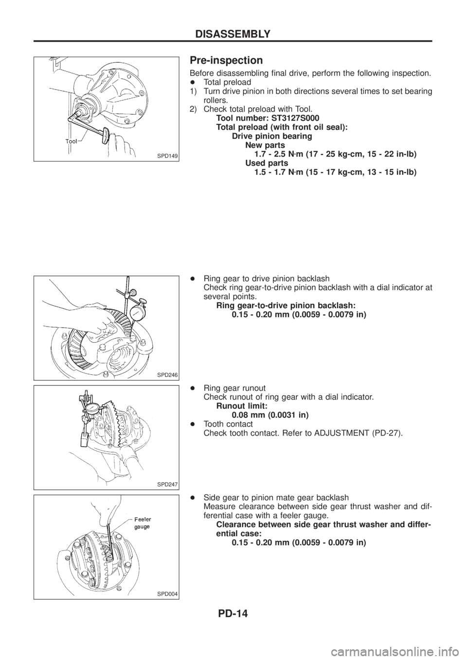
Pre-inspection
Before disassembling ®nal drive, perform the following inspection.
+Total preload
1) Turn drive pinion in both directions several times to set bearing
rollers.
2) Check total preload with Tool.
Tool number: ST3127S000
Total preload (with front oil seal):
Drive pinion bearing
New parts
1.7 - 2.5 Nzm (17 - 25 kg-cm, 15 - 22 in-lb)
Used parts
1.5 - 1.7 Nzm (15 - 17 kg-cm, 13 - 15 in-lb)
+Ring gear to drive pinion backlash
Check ring gear-to-drive pinion backlash with a dial indicator at
several points.
Ring gear-to-drive pinion backlash:
0.15 - 0.20 mm (0.0059 - 0.0079 in)
+Ring gear runout
Check runout of ring gear with a dial indicator.
Runout limit:
0.08 mm (0.0031 in)
+Tooth contact
Check tooth contact. Refer to ADJUSTMENT (PD-27).
+Side gear to pinion mate gear backlash
Measure clearance between side gear thrust washer and dif-
ferential case with a feeler gauge.
Clearance between side gear thrust washer and differ-
ential case:
0.15 - 0.20 mm (0.0059 - 0.0079 in)
SPD149
SPD246
SPD247
SPD004
DISASSEMBLY
PD-14
Page 1058 of 1226
Be careful to keep the side bearing outer races together with
their respective inner cones Ð do not mix them up.
6. Loosen drive pinion nut with Tool.
Tool number: KV38104700
7. Remove companion ¯ange with puller.
8. Take out drive pinion together with pinion rear bearing inner
cone, drive pinion bearing spacer and pinion bearing adjusting
shim with soft hammer.
9. Remove front oil seal and pinion front bearing inner cone.
10. Remove pinion bearing outer races with a brass drift.
SPD011
SPD012
SPD686
SPD687
SPD563
DISASSEMBLY
Differential Carrier (Cont'd)
PD-16
Page 1063 of 1226
Disassembly
1. Remove side bearing inner cone with Tool.
2. Loosen ring gear bolts in a criss-cross pattern.
3. Tap ring gear off gear case with a soft hammer.
Tap evenly all around to keep ring gear from binding.
4. Loosen screws on differential cases A and B using a press.
5. Separate differential cases A and B. Draw out component parts
(discs and plates, etc.).
Put marks on gears, discs and plates so that they can be rein-
stalled in their original positions from which they were
removed.
Inspection
CONTACT SURFACES
1. Clean the disassembled parts in suitable solvent and blow dry
with compressed air.
2. If following surfaces are found with burrs or scratches, smooth
with oil stone.
V1Differential case A
V2Differential case B
V3Pressure ring
V4Thrust washer
V5Pinion mate shaft
V6Thrust block
V7Pinion mate gear
V8Side gear
SPD476
SPD507
SPD503
LIMITED SLIP DIFFERENTIAL
PD-21
Page 1066 of 1226

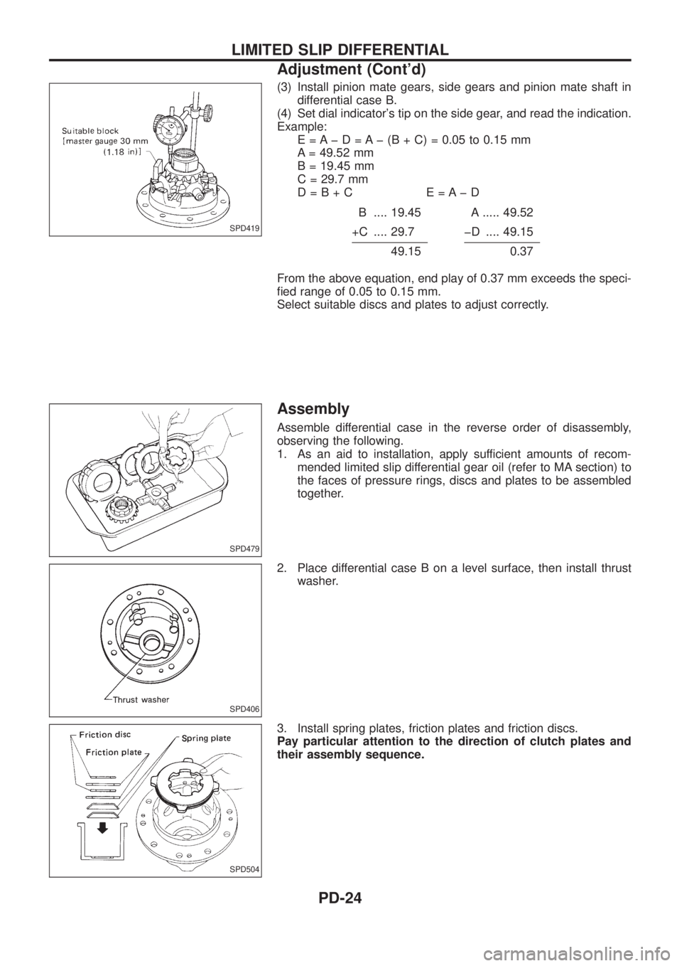
(3) Install pinion mate gears, side gears and pinion mate shaft in
differential case B.
(4) Set dial indicator's tip on the side gear, and read the indication.
Example:
E = A þ D = A þ (B + C) = 0.05 to 0.15 mm
A = 49.52 mm
B = 19.45 mm
C = 29.7 mm
D=B+C E=AþD
B .... 19.45 A ..... 49.52
+C .... 29.7 þD .... 49.15
49.150.37
From the above equation, end play of 0.37 mm exceeds the speci-
®ed range of 0.05 to 0.15 mm.
Select suitable discs and plates to adjust correctly.
Assembly
Assemble differential case in the reverse order of disassembly,
observing the following.
1. As an aid to installation, apply sufficient amounts of recom-
mended limited slip differential gear oil (refer to MA section) to
the faces of pressure rings, discs and plates to be assembled
together.
2. Place differential case B on a level surface, then install thrust
washer.
3. Install spring plates, friction plates and friction discs.
Pay particular attention to the direction of clutch plates and
their assembly sequence.
SPD419
SPD479
SPD406
SPD504
LIMITED SLIP DIFFERENTIAL
Adjustment (Cont'd)
PD-24
Page 1067 of 1226
4. Install pressure ring.
5. Install side gear by inserting projected portion of disc.
6. Install pinion mate gears and shaft.
Always attach pinion mate shaft to ``V'' groove in pressure ring
with ¯at surfaces facing up and down.
7. Install thrust block.
8. Install differential case A side components in the opposite way
of differential case B components.
9. Apply gear oil to differential case A, and attach thrust washer
to it.
SPD481
SPD482
SPD483
SPD505
SPD506
LIMITED SLIP DIFFERENTIAL
Assembly (Cont'd)
PD-25
Page 1071 of 1226
![NISSAN PATROL 2006 Service Manual Example (H233B):N = 0.30
H=2
D¢=þ1
S=0
T=Nþ[(HþD ¢þS)x0.01]+2.75
=0.40þ[{2þ(þ1)þ0}x0.01]+2.75
(1) H ........................................................................\
2 þD¢........ NISSAN PATROL 2006 Service Manual Example (H233B):N = 0.30
H=2
D¢=þ1
S=0
T=Nþ[(HþD ¢þS)x0.01]+2.75
=0.40þ[{2þ(þ1)þ0}x0.01]+2.75
(1) H ........................................................................\
2 þD¢........](/manual-img/5/57368/w960_57368-1070.png)
Example (H233B):N = 0.30
H=2
D¢=þ1
S=0
T=Nþ[(HþD ¢þS)x0.01]+2.75
=0.40þ[{2þ(þ1)þ0}x0.01]+2.75
(1) H ........................................................................\
2 þD¢................................................................. þ(þ1)
3
þS ...................................................................... þ0
3
(2) 3 x 0.01
0.03
(3)N...................................................................0.40 þ0.03
0.37
(4)0.37 +2.75
3.12
\ T=3.12
7. Select the proper pinion height washer. Drive pinion height adjusting washer:Refer to SDS (PD-0, 53).
If you cannot ®nd the desired thickness of washer, use washer
with thickness closest to the calculated value.
Example (H233B): Calculatedvalue...T=3.12 mm
Usedwasher...T=3.12 mm
Tooth Contact
Gear tooth contact pattern check is necessary to verify correct
relationship between ring gear and drive pinion.
Hypoid gear sets which are not positioned properly in relation to
one another may be noisy, or have short life or both. With a pat-
tern check, the most desirable contact for low noise level and long
life can be assured.
1. Thoroughly clean ring gear and drive pinion teeth.
2. Sparingly apply a mixture of powdered ferric oxide and oil orequivalent to 3 or 4 teeth of ring gear drive side.
SPD005
ADJUSTMENT
Drive Pinion Height (Cont'd)
PD-29