Page 1773 of 2305
command valve (5) to clutch K1 (6). The multiple-disc
holding clutch B1 (7) is deactivated (unpressurized).
The spring of the shift pressure shift valve (3) pushes
the valve back to its basic position.
21 - 30 AUTOMATIC TRANSMISSION NAG1 - SERVICE INFORMATIONVA
Page 1774 of 2305
Shift Phase - 2-1 Shift Phase 1
The 1-2/4-5 shift solenoid (1) (Fig. 20) is turned ON
to apply shift pressure (p-S) to the end face of the
1-2/4-5 command valve (5). This allows the commandvalve to up-shift and the shift pressure coming from
the 1-2/4-5 shift valve (3) is routed to the holding
clutch B1 (7) via the command valve.
Fig. 20 Shift Phase - 2-1 Shift Phase 1
1 - 1-2/4-5 SHIFT SOLENOID 5 - 1-2/4-5 COMMAND VALVE
2 - 1-2/4-5 OVERLAP VALVE 6 - DRIVING CLUTCH K1
3 - 1-2/4-5 SHIFT PRESSURE SHIFT VALVE 7 - HOLDING CLUTCH B1
4 - 1-2/4-5 HOLDING PRESSURE SHIFT VALVE 8 - SHIFT PRESSURE REGULATOR VALVE
VAAUTOMATIC TRANSMISSION NAG1 - SERVICE INFORMATION 21 - 31
Page 1775 of 2305
Simultaneously, the pressure in the releasing
clutch, K1 (6), is regulated at the 1-2/4-5 overlap
valve (2). The pressure in the K1 clutch as it disen-
gages is controlled during the shift phase depending
on engine load, via the modulating pressure
(p-MOD), and the shift pressure in clutch B1 (7). The
increasing shift pressure in clutch B1, which also
acts on the end face of the overlap valve, reduces the
overlap pressure.
21 - 32 AUTOMATIC TRANSMISSION NAG1 - SERVICE INFORMATIONVA
Page 1776 of 2305
Shift Phase - 2-1 Shift Phase 2
The pressure in clutch B1 (7) (Fig. 21) acting on
the end face of the 1-2/4-5 holding valve (4) forces the
valve to up-shift against the spring pressure andallows line pressure (p-A) to pass through the com-
mand valve (5).
Fig. 21 Shift Phase - 2-1 Shift Phase 2
1 - 1-2/4-5 SHIFT SOLENOID 5 - 1-2/4-5 COMMAND VALVE
2 - 1-2/4-5 OVERLAP VALVE 6 - DRIVING CLUTCH K1
3 - 1-2/4-5 SHIFT PRESSURE SHIFT VALVE 7 - HOLDING CLUTCH B1
4 - 1-2/4-5 HOLDING PRESSURE SHIFT VALVE 8 - SHIFT PRESSURE REGULATOR VALVE
VAAUTOMATIC TRANSMISSION NAG1 - SERVICE INFORMATION 21 - 33
Page 1777 of 2305
2-1 Shift - First Gear Engaged
After the gear change is complete, the 1-2/4-5 shift
solenoid (1) (Fig. 22) is turned off. This reduces the
pressure on the end face of the 1-2/4-5 commandvalve (5) to 0 psi and the spring pressure downshifts
the valve to its initial position. The line pressure
(p-A) is switched to the holding clutch B1 (7) and the
Fig. 22 First Gear Engaged
1 - 1-2/4-5 SHIFT SOLENOID 5 - 1-2/4-5 COMMAND VALVE
2 - 1-2/4-5 OVERLAP VALVE 6 - DRIVING CLUTCH K1
3 - 1-2/4-5 SHIFT PRESSURE SHIFT VALVE 7 - HOLDING CLUTCH B1
4 - 1-2/4-5 HOLDING PRESSURE SHIFT VALVE 8 - SHIFT PRESSURE REGULATOR VALVE
21 - 34 AUTOMATIC TRANSMISSION NAG1 - SERVICE INFORMATIONVA
Page 1778 of 2305
end face of the holding valve by the downshifted com-
mand valve. The upshifted holding valve also allows
the remaining pressure in clutch K1 (6) to be vented.
VAAUTOMATIC TRANSMISSION NAG1 - SERVICE INFORMATION 21 - 35
Page 1779 of 2305
Gear Shift N to D (1st gear) - Engine Started
With the engine started (Fig. 23) and the gearshift
lever in the NEUTRAL or PARK positions, holding
clutch B1 (1) and driving clutch K3 (4) are applied
and the various valves in the 1-2/4-5 shift group are
positioned to apply pressure to the holding clutch B2.
Fig. 23 Engine Started
1 - HOLDING CLUTCH B1 11 - PRESSURE HOLDING VALVE
2 - DRIVING CLUTCH K1 12 - 3-4 HOLDING PRESSURE SHIFT VALVE
3 - HOLDING CLUTCH B3 13 - 3-4 COMMAND VALVE
4 - DRIVING CLUTCH K3 14 - 3-4 SHIFT PRESSURE SHIFT VALVE
5 - HOLDING CLUTCH B2 PISTON 15 - 3-4 OVERLAP REGULATING VALVE
6 - HOLDING CLUTCH B2 PISTON OPPOSING FACE 16 - BALL VALVE
7 - SHIFT PRESSURE REGULATING SOLENOID 17 - 1-2/4-5 COMMAND VALVE
8 - SHIFT PRESSURE REGULATING VALVE 18 - 1-2/4-5 COMMAND VALVE
9 - SHIFT VALVE B2 19 - BALL VALVE
10 - 3-4 SHIFT SOLENOID
21 - 36 AUTOMATIC TRANSMISSION NAG1 - SERVICE INFORMATIONVA
Page 1780 of 2305

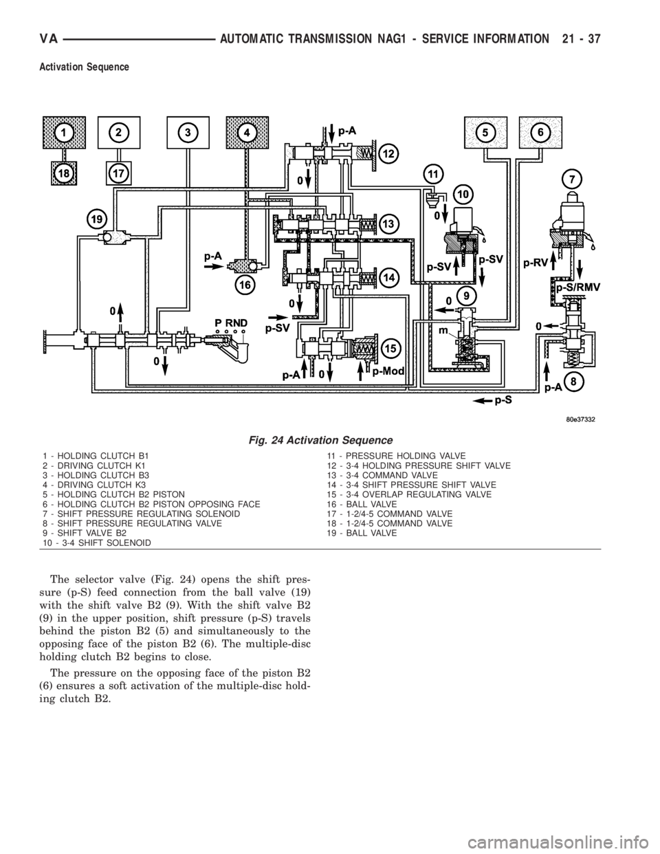
Activation Sequence
The selector valve (Fig. 24) opens the shift pres-
sure (p-S) feed connection from the ball valve (19)
with the shift valve B2 (9). With the shift valve B2
(9) in the upper position, shift pressure (p-S) travels
behind the piston B2 (5) and simultaneously to the
opposing face of the piston B2 (6). The multiple-disc
holding clutch B2 begins to close.
The pressure on the opposing face of the piston B2
(6) ensures a soft activation of the multiple-disc hold-
ing clutch B2.
Fig. 24 Activation Sequence
1 - HOLDING CLUTCH B1 11 - PRESSURE HOLDING VALVE
2 - DRIVING CLUTCH K1 12 - 3-4 HOLDING PRESSURE SHIFT VALVE
3 - HOLDING CLUTCH B3 13 - 3-4 COMMAND VALVE
4 - DRIVING CLUTCH K3 14 - 3-4 SHIFT PRESSURE SHIFT VALVE
5 - HOLDING CLUTCH B2 PISTON 15 - 3-4 OVERLAP REGULATING VALVE
6 - HOLDING CLUTCH B2 PISTON OPPOSING FACE 16 - BALL VALVE
7 - SHIFT PRESSURE REGULATING SOLENOID 17 - 1-2/4-5 COMMAND VALVE
8 - SHIFT PRESSURE REGULATING VALVE 18 - 1-2/4-5 COMMAND VALVE
9 - SHIFT VALVE B2 19 - BALL VALVE
10 - 3-4 SHIFT SOLENOID
VAAUTOMATIC TRANSMISSION NAG1 - SERVICE INFORMATION 21 - 37