Page 1789 of 2305

(16) Disconnect ground strap and tie back to one
side.
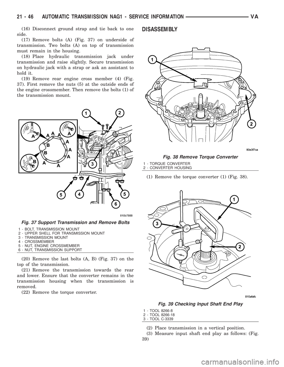
(17) Remove bolts (A) (Fig. 37) on underside of
transmission. Two bolts (A) on top of transmission
must remain in the housing.
(18) Place hydraulic transmission jack under
transmission and raise slightly. Secure transmission
on hydraulic jack with a strap or ask an assistant to
hold it.
(19) Remove rear engine cross member (4) (Fig.
37). First remove the nuts (5) at the outside ends of
the engine crossmember. Then remove the bolts (1) of
the transmission mount.
(20) Remove the last bolts (A, B) (Fig. 37) on the
top of the transmission.
(21) Remove the transmission towards the rear
and lower. Ensure that the converter remains in the
transmission housing when the transmission is
removed.
(22) Remove the torque converter.DISASSEMBLY
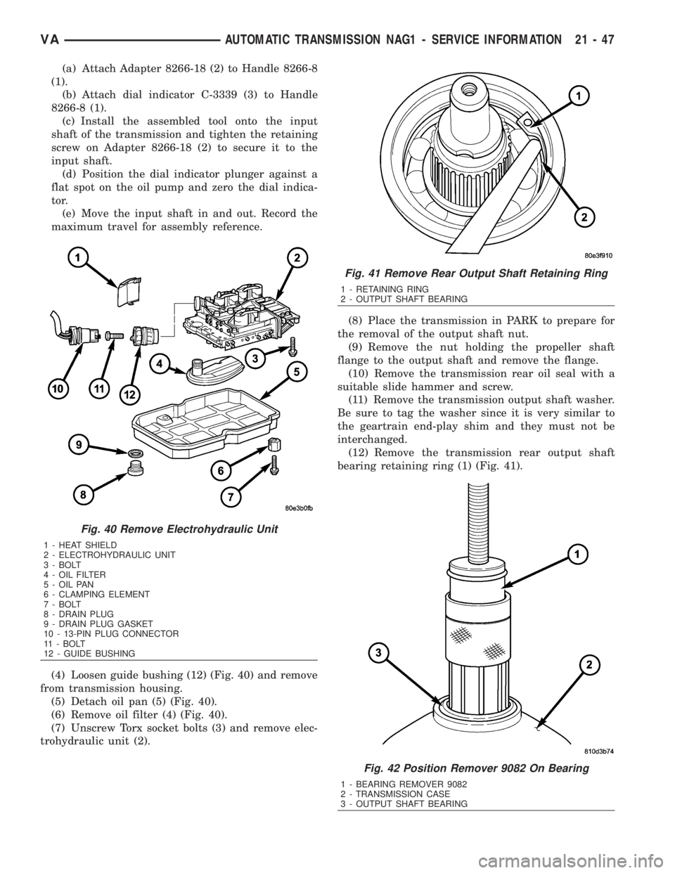
(1) Remove the torque converter (1) (Fig. 38).
(2) Place transmission in a vertical position.
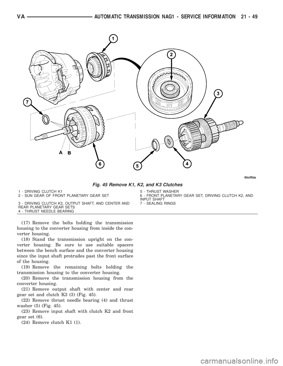
(3) Measure input shaft end play as follows: (Fig.
39)
Fig. 37 Support Transmission and Remove Bolts
1 - BOLT, TRANSMISSION MOUNT
2 - UPPER SHELL FOR TRANSMISSION MOUNT
3 - TRANSMISSION MOUNT
4 - CROSSMEMBER
5 - NUT, ENGINE CROSSMEMBER
6 - NUT, TRANSMISSION SUPPORT
Fig. 38 Remove Torque Converter
1 - TORQUE CONVERTER
2 - CONVERTER HOUSING
Fig. 39 Checking Input Shaft End Play
1 - TOOL 8266-8
2 - TOOL 8266-18
3 - TOOL C-3339
21 - 46 AUTOMATIC TRANSMISSION NAG1 - SERVICE INFORMATIONVA
Page 1790 of 2305

(a) Attach Adapter 8266-18 (2) to Handle 8266-8
(1).
(b) Attach dial indicator C-3339 (3) to Handle
8266-8 (1).
(c) Install the assembled tool onto the input
shaft of the transmission and tighten the retaining
screw on Adapter 8266-18 (2) to secure it to the
input shaft.
(d) Position the dial indicator plunger against a
flat spot on the oil pump and zero the dial indica-
tor.
(e) Move the input shaft in and out. Record the
maximum travel for assembly reference.
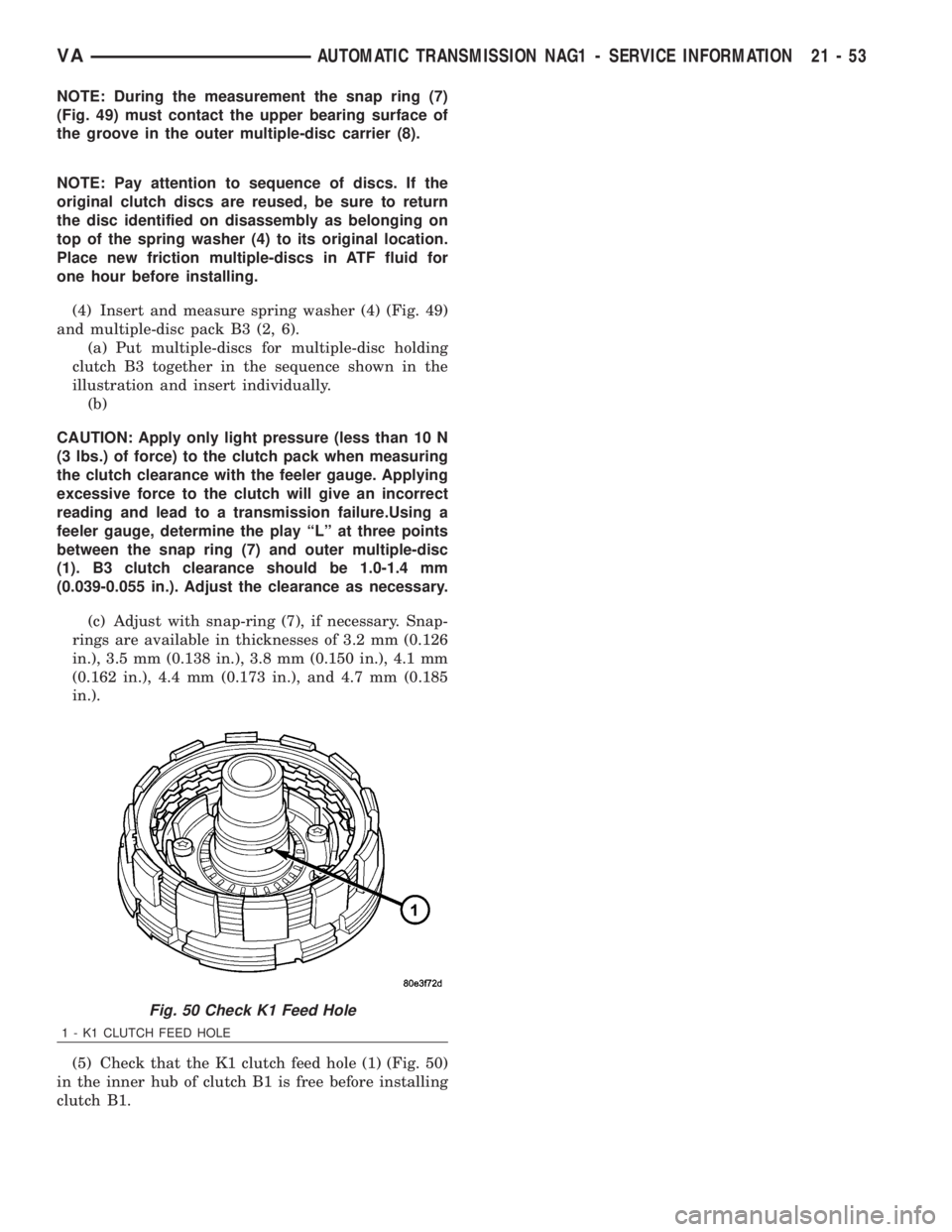
(4) Loosen guide bushing (12) (Fig. 40) and remove
from transmission housing.
(5) Detach oil pan (5) (Fig. 40).
(6) Remove oil filter (4) (Fig. 40).
(7) Unscrew Torx socket bolts (3) and remove elec-
trohydraulic unit (2).(8) Place the transmission in PARK to prepare for
the removal of the output shaft nut.
(9) Remove the nut holding the propeller shaft
flange to the output shaft and remove the flange.
(10) Remove the transmission rear oil seal with a
suitable slide hammer and screw.
(11) Remove the transmission output shaft washer.
Be sure to tag the washer since it is very similar to
the geartrain end-play shim and they must not be
interchanged.
(12) Remove the transmission rear output shaft
bearing retaining ring (1) (Fig. 41).
Fig. 40 Remove Electrohydraulic Unit
1 - HEAT SHIELD
2 - ELECTROHYDRAULIC UNIT
3 - BOLT
4 - OIL FILTER
5 - OIL PAN
6 - CLAMPING ELEMENT
7 - BOLT
8 - DRAIN PLUG
9 - DRAIN PLUG GASKET
10 - 13-PIN PLUG CONNECTOR
11 - BOLT
12 - GUIDE BUSHING
Fig. 41 Remove Rear Output Shaft Retaining Ring
1 - RETAINING RING
2 - OUTPUT SHAFT BEARING
Fig. 42 Position Remover 9082 On Bearing
1 - BEARING REMOVER 9082
2 - TRANSMISSION CASE
3 - OUTPUT SHAFT BEARING
VAAUTOMATIC TRANSMISSION NAG1 - SERVICE INFORMATION 21 - 47
Page 1791 of 2305
(13) Position Bearing Remover 9082 (1) (Fig. 42)
over the inner race of the output shaft bearing (3).
(14) Slide the collar (3) (Fig. 43) on the Bearing
Remover 9082 (1) downward over the fingers (4) of
the tool.(15) Remove the output shaft bearing (3) (Fig. 44).
(16) Remove the geartrain end-play shim from the
output shaft. Be sure to tag the shim since it is very
similar to the output shaft washer and they must not
be interchanged.
Fig. 43 Slide Remover 9082 Collar Downward
1 - BEARING REMOVER 9082
2 - TRANSMISSION CASE
3 - COLLAR
4 - FINGERS
Fig. 44 Remove Output Shaft Bearing
1 - BEARING REMOVER 9082
2 - TRANSMISSION CASE
3 - OUTPUT SHAFT BEARING
21 - 48 AUTOMATIC TRANSMISSION NAG1 - SERVICE INFORMATIONVA
Page 1792 of 2305

(17) Remove the bolts holding the transmission
housing to the converter housing from inside the con-
verter housing.
(18) Stand the transmission upright on the con-
verter housing. Be sure to use suitable spacers
between the bench surface and the converter housing
since the input shaft protrudes past the front surface
of the housing.
(19) Remove the remaining bolts holding the
transmission housing to the converter housing.
(20) Remove the transmission housing from the
converter housing.
(21) Remove output shaft with center and rear
gear set and clutch K3 (3) (Fig. 45).
(22) Remove thrust needle bearing (4) and thrust
washer (5) (Fig. 45).
(23) Remove input shaft with clutch K2 and front
gear set (6).
(24) Remove clutch K1 (1).
Fig. 45 Remove K1, K2, and K3 Clutches
1 - DRIVING CLUTCH K1 5 - THRUST WASHER
2 - SUN GEAR OF FRONT PLANETARY GEAR SET 6 - FRONT PLANETARY GEAR SET, DRIVING CLUTCH K2, AND
INPUT SHAFT
3 - DRIVING CLUTCH K3, OUTPUT SHAFT, AND CENTER AND
REAR PLANETARY GEAR SETS7 - SEALING RINGS
4 - THRUST NEEDLE BEARING
VAAUTOMATIC TRANSMISSION NAG1 - SERVICE INFORMATION 21 - 49
Page 1793 of 2305
(25) Unscrew Torx socket bolts (4) (Fig. 46) and
remove oil pump (6). Screw two opposed bolts into
the oil pump housing and press the oil pump out of
the converter housing by applying light blows with a
plastic hammer.
(26) Remove and discard the torque converter hub
seal and the oil pump outer o-ring seal from the oil
pump.
(27) Unscrew Torx socket bolts (1) (Fig. 46) and
remove multiple-disc holding clutch B1 (5) from con-
verter housing. Screw two opposed bolts into the
multiple-disc holding clutch B1 (5) and separate from
the converter housing by applying light blows with a
plastic hammer.
(28) Detach intermediate plate (3) (Fig. 46) from
converter housing (2).
Fig. 46 Remove Holding Clutch B1 and Oil Pump
1 - BOLTS - M6X32 4 - BOLTS - M8X35
2 - CONVERTER HOUSING 5 - HOLDING CLUTCH B1
3 - INTERMEDIATE PLATE 6 - OIL PUMP
21 - 50 AUTOMATIC TRANSMISSION NAG1 - SERVICE INFORMATIONVA
Page 1794 of 2305
(29) Remove multiple-disc pack B3 (2) (Fig. 47)
and spring washer (3) by removing snap-ring (1) in
transmission housing. To facilitate removal of the
snap-ring (1), compress the multiple-disc pack B3 (2).
Note which clutch disc is removed just prior to the
spring washer (3) for re-assembly. If the clutch discs
are re-used, this disc must be returned to its original
position on top of the spring washer.
(30) Unscrew Torx socket bolts (7) (Fig. 47).
(31) Remove multiple-disc holding clutch B2 (4)
(Fig. 47) from transmission housing. The externally
toothed disc carrier for multiple-disc holding clutch
B2 is also the piston for multiple-disc holding clutch
B3.
(32) Remove parking lock gear (5) (Fig. 47).
Fig. 47 Remove B2, B3, and Parking Gear
1 - SNAP-RING 5 - PARK GEAR
2 - HOLDING CLUTCH B3 DISCS 6 - TRANSMISSION HOUSING
3 - SPRING WASHER 7 - BOLTS - M8X60
4 - HOLDING CLUTCH B2
VAAUTOMATIC TRANSMISSION NAG1 - SERVICE INFORMATION 21 - 51
Page 1795 of 2305
ASSEMBLY
(1) Insert parking lock gear (5) (Fig. 48).
(2) Install multiple-disc holding clutch B2 (4) in
transmission housing (6) (Fig. 48).
(3) Screw in both Torx socket bolts (7). Tighten the
bolts to 16 N´m (141 in.lbs.).
Fig. 48 Install B2, B3, and Parking Gear
1 - SNAP-RING 5 - PARK GEAR
2 - HOLDING CLUTCH B3 DISCS 6 - TRANSMISSION HOUSING
3 - SPRING WASHER 7 - BOLTS - M8X60
4 - HOLDING CLUTCH B2
Fig. 49 Measure B3 Clutch Clearance
1 - OUTER DISC - 6.5 MM
(0.256 IN.)5 - PISTON
2 - OUTER DISCS - 1.8 MM
(0.071 IN.)6 - FRICTION DISCS
3 - OUTER DISCS - 1.8 MM
(0.071 IN.)7 - SNAP-RING
4 - SPRING WASHER 8 - B3 DISC CARRIER
21 - 52 AUTOMATIC TRANSMISSION NAG1 - SERVICE INFORMATIONVA
Page 1796 of 2305

NOTE: During the measurement the snap ring (7)
(Fig. 49) must contact the upper bearing surface of
the groove in the outer multiple-disc carrier (8).
NOTE: Pay attention to sequence of discs. If the
original clutch discs are reused, be sure to return
the disc identified on disassembly as belonging on
top of the spring washer (4) to its original location.
Place new friction multiple-discs in ATF fluid for
one hour before installing.
(4) Insert and measure spring washer (4) (Fig. 49)
and multiple-disc pack B3 (2, 6).
(a) Put multiple-discs for multiple-disc holding
clutch B3 together in the sequence shown in the
illustration and insert individually.
(b)
CAUTION: Apply only light pressure (less than 10 N
(3 lbs.) of force) to the clutch pack when measuring
the clutch clearance with the feeler gauge. Applying
excessive force to the clutch will give an incorrect
reading and lead to a transmission failure.Using a
feeler gauge, determine the play ªLº at three points
between the snap ring (7) and outer multiple-disc
(1). B3 clutch clearance should be 1.0-1.4 mm
(0.039-0.055 in.). Adjust the clearance as necessary.
(c) Adjust with snap-ring (7), if necessary. Snap-
rings are available in thicknesses of 3.2 mm (0.126
in.), 3.5 mm (0.138 in.), 3.8 mm (0.150 in.), 4.1 mm
(0.162 in.), 4.4 mm (0.173 in.), and 4.7 mm (0.185
in.).
(5) Check that the K1 clutch feed hole (1) (Fig. 50)
in the inner hub of clutch B1 is free before installing
clutch B1.
Fig. 50 Check K1 Feed Hole
1 - K1 CLUTCH FEED HOLE
VAAUTOMATIC TRANSMISSION NAG1 - SERVICE INFORMATION 21 - 53