2006 MERCEDES-BENZ SPRINTER engine
[x] Cancel search: enginePage 1651 of 2305
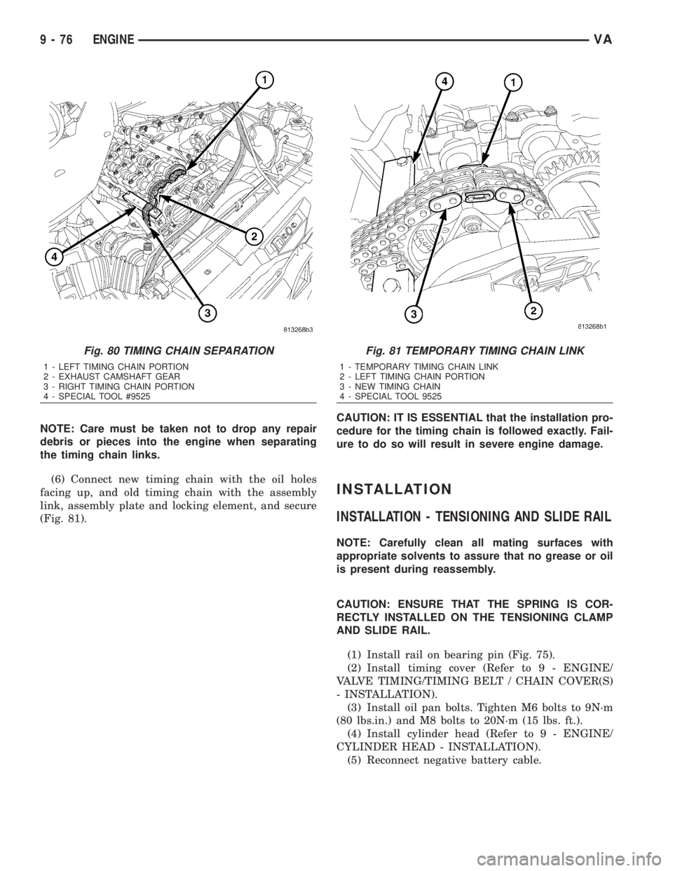
NOTE: Care must be taken not to drop any repair
debris or pieces into the engine when separating
the timing chain links.
(6) Connect new timing chain with the oil holes
facing up, and old timing chain with the assembly
link, assembly plate and locking element, and secure
(Fig. 81).CAUTION: IT IS ESSENTIAL that the installation pro-
cedure for the timing chain is followed exactly. Fail-
ure to do so will result in severe engine damage.
INSTALLATION
INSTALLATION - TENSIONING AND SLIDE RAIL
NOTE: Carefully clean all mating surfaces with
appropriate solvents to assure that no grease or oil
is present during reassembly.
CAUTION: ENSURE THAT THE SPRING IS COR-
RECTLY INSTALLED ON THE TENSIONING CLAMP
AND SLIDE RAIL.
(1) Install rail on bearing pin (Fig. 75).
(2) Install timing cover (Refer to 9 - ENGINE/
VALVE TIMING/TIMING BELT / CHAIN COVER(S)
- INSTALLATION).
(3) Install oil pan bolts. Tighten M6 bolts to 9N´m
(80 lbs.in.) and M8 bolts to 20N´m (15 lbs. ft.).
(4) Install cylinder head (Refer to 9 - ENGINE/
CYLINDER HEAD - INSTALLATION).
(5) Reconnect negative battery cable.
Fig. 80 TIMING CHAIN SEPARATION
1 - LEFT TIMING CHAIN PORTION
2 - EXHAUST CAMSHAFT GEAR
3 - RIGHT TIMING CHAIN PORTION
4 - SPECIAL TOOL #9525
Fig. 81 TEMPORARY TIMING CHAIN LINK
1 - TEMPORARY TIMING CHAIN LINK
2 - LEFT TIMING CHAIN PORTION
3 - NEW TIMING CHAIN
4 - SPECIAL TOOL 9525
9 - 76 ENGINEVA
Page 1652 of 2305
WARNING: USE EXTREME CAUTION WHEN THE
ENGINE IS OPERATING. DO NOT STAND IN A
DIRECT LINE WITH THE FAN. DO NOT PUT YOUR
HANDS NEAR THE PULLEYS, BELTS OR FAN. DO
NOT WEAR LOOSE CLOTHES.
(6) Start the engine, allow to warm, turn engine
off and inspect for leaks. Care must be take to
observe the fuel system warning (Refer to 14 - FUEL
SYSTEM - WARNING).
INSTALLATION - INTERMEDIATE GEAR
NOTE: Refer to appropriate injector servicing proce-
dures for cleaning of injectors and recesses.
(1) Install intermediate gear and bushing. Tighten
bolt to 40N´m (30 lbs.ft.)
(2) Install the intake camshaft (Refer to 9 -
ENGINE/CYLINDER HEAD/CAMSHAFT(S) -
INSTALLATION).
(3) Install exhaust camshaft sprocket, noting
dowel pin alignment. Tighten bolt to 18 N´m (159 lbs.
in.).
WARNING: NO FIRE, FLAMES OR SMOKING. SER-
VICE VEHICLE IN WELL VENTILATED AREA. RISK
OF INJURY FROM INHALING OR SWALLOWING
FUEL. RISK OF INJURY TO EYES AND SKIN FROM
CONTACT WITH FUEL. WEAR PROTECTIVE CLOTH-
ING.
(4) Install high pressure pump (Refer to 14 -
FUEL SYSTEM/FUEL DELIVERY/FUEL INJEC-
TION PUMP - INSTALLATION).
(5) Install top slide rail (Refer to 9 - ENGINE/
VALVE TIMING/TIMING BELT/CHAIN AND
SPROCKETS - INSTALLATION).
(6) Install cylinder head front cover (Refer to 9 -
ENGINE/CYLINDER HEAD - INSTALLATION).
(7) Install timing chain tensioner with new gasket
(Refer to 9 - ENGINE/VALVE TIMING/TIMING
BELT/CHAIN AND SPROCKETS - INSTALLA-
TION).
NOTE: Inspect basic position of camshaft and reset
if necessary (Refer to 9 - ENGINE/CYLINDER HEAD/
CAMSHAFT(S) - STANDARD PROCEDURE).
(8) Remove camshaft locking pin.
(9) Install cylinder head cover (Refer to 9 -
ENGINE/CYLINDER HEAD/CYLINDER HEAD
COVER(S) - INSTALLATION).
WARNING: NO FIRE, FLAMES OR SMOKING. SER-
VICE VEHICLE IN WELL VENTILATED AREA. RISK
OF INJURY FROM INHALING OR SWALLOWING
FUEL. RISK OF INJURY TO EYES AND SKIN FROMCONTACT WITH FUEL. WEAR PROTECTIVE CLOTH-
ING.
(10) Install fuel high pressure lines and injectors
(Refer to 14 - FUEL SYSTEM/FUEL INJECTION/
FUEL INJECTOR - INSTALLATION).
(11) Install engine cover (Refer to 9 - ENGINE -
INSTALLATION).
(12) Connect negative battery cable.
WARNING: USE EXTREME CAUTION WHEN THE
ENGINE IS OPERATING. DO NOT STAND IN A
DIRECT LINE WITH FAN. DO NOT PUT YOUR
HANDS NEAR THE PULLEYS, BELTS OR FAN. DO
NOT WEAR LOOSE CLOTHING.
(13) Start engine and inspect for leaks. Care must
be taken to observe the fuel system warning (Refer to
14 - FUEL SYSTEM - WARNING).
INSTALLATION - TIMING CHAIN TENSIONING
RAIL
NOTE: Carefully clean all mating surfaces with
appropriate solvents to assure that no grease or oil
is present during reassembly.
(1) Install tensioning rail on bearing pin
(2) Install timing cover (Refer to 9 - ENGINE/
VALVE TIMING/TIMING BELT / CHAIN COVER(S)
- INSTALLATION).
(3) Install oil pan and bolts. Tighten M6 bolts to
9N´m (80 lbs.in.) and M8 bolts to 20N´m (15 lbs. ft.).
(4) Install cylinder head (Refer to 9 - ENGINE/
CYLINDER HEAD - INSTALLATION).
(5) Reconnect negative battery cable.
WARNING: USE EXTREME CAUTION WHEN THE
ENGINE IS OPERATING. DO NOT PUT YOUR
HANDS NEAR THE PULLEYS, BELTS OR FAN. DO
NOT WEAR LOOSE CLOTHES.
(6) Start the engine and inspect for leaks. Care
must be taken to observe the fuel system warning
(Refer to 14 - FUEL SYSTEM - WARNING).
ADJUSTMENTS
INSTALLATION - TIMING CHAIN
CAUTION: IT IS ESSENTIAL that the installation pro-
cedure is followed exactly. Failure to do so will
result in severe engine damage.
CAUTION: Cover timing case recesses to prevent
foreign material from entering engine.
VAENGINE 9 - 77
Page 1653 of 2305
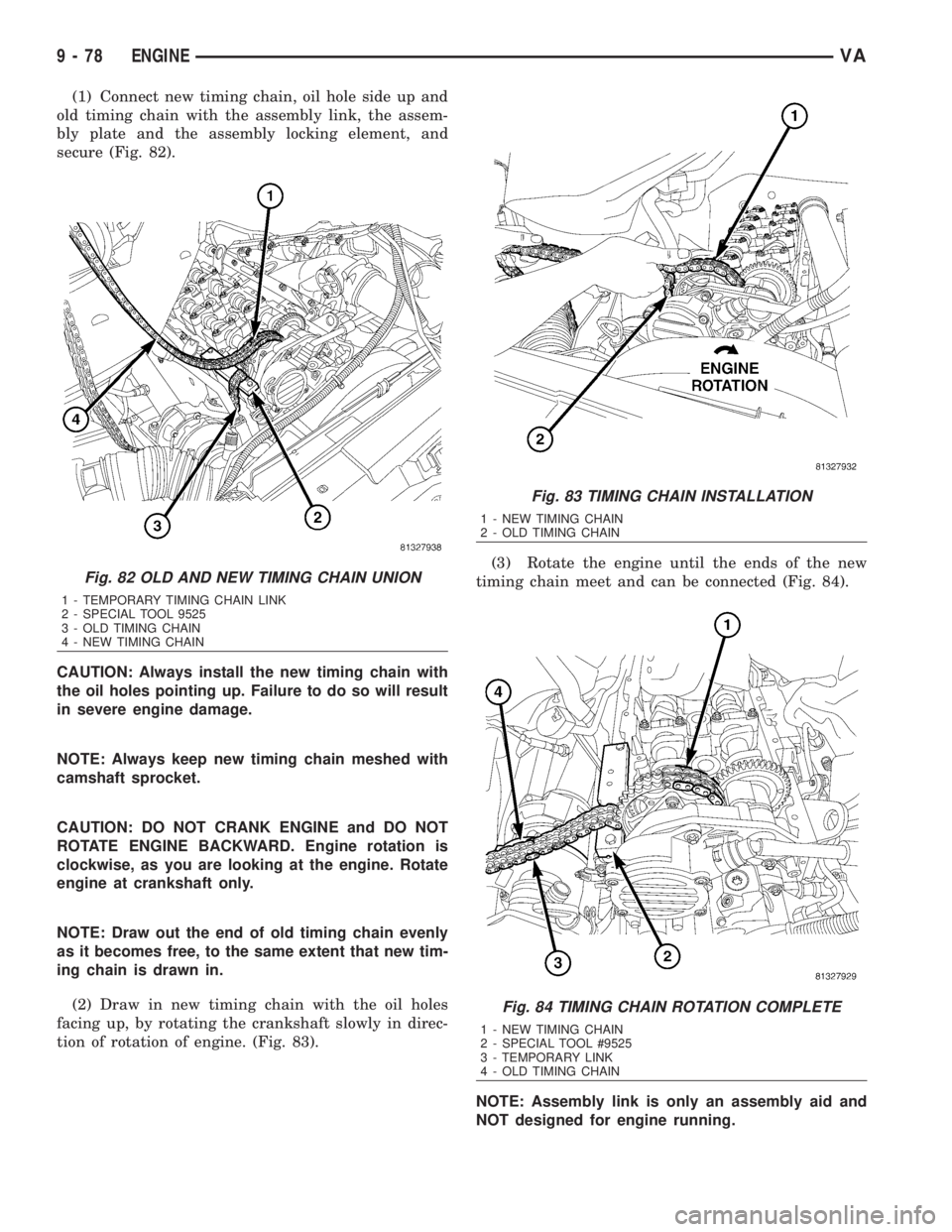
(1) Connect new timing chain, oil hole side up and
old timing chain with the assembly link, the assem-
bly plate and the assembly locking element, and
secure (Fig. 82).
CAUTION: Always install the new timing chain with
the oil holes pointing up. Failure to do so will result
in severe engine damage.
NOTE: Always keep new timing chain meshed with
camshaft sprocket.
CAUTION: DO NOT CRANK ENGINE and DO NOT
ROTATE ENGINE BACKWARD. Engine rotation is
clockwise, as you are looking at the engine. Rotate
engine at crankshaft only.
NOTE: Draw out the end of old timing chain evenly
as it becomes free, to the same extent that new tim-
ing chain is drawn in.
(2) Draw in new timing chain with the oil holes
facing up, by rotating the crankshaft slowly in direc-
tion of rotation of engine. (Fig. 83).(3) Rotate the engine until the ends of the new
timing chain meet and can be connected (Fig. 84).
NOTE: Assembly link is only an assembly aid and
NOT designed for engine running.
Fig. 82 OLD AND NEW TIMING CHAIN UNION
1 - TEMPORARY TIMING CHAIN LINK
2 - SPECIAL TOOL 9525
3 - OLD TIMING CHAIN
4 - NEW TIMING CHAIN
Fig. 83 TIMING CHAIN INSTALLATION
1 - NEW TIMING CHAIN
2 - OLD TIMING CHAIN
Fig. 84 TIMING CHAIN ROTATION COMPLETE
1 - NEW TIMING CHAIN
2 - SPECIAL TOOL #9525
3 - TEMPORARY LINK
4 - OLD TIMING CHAIN
9 - 78 ENGINEVA
Page 1654 of 2305
(4) Remove assembly locking element, assembly
outer plate and assembly link.
CAUTION: Cover timing case recesses to prevent
foreign material from entering engine.
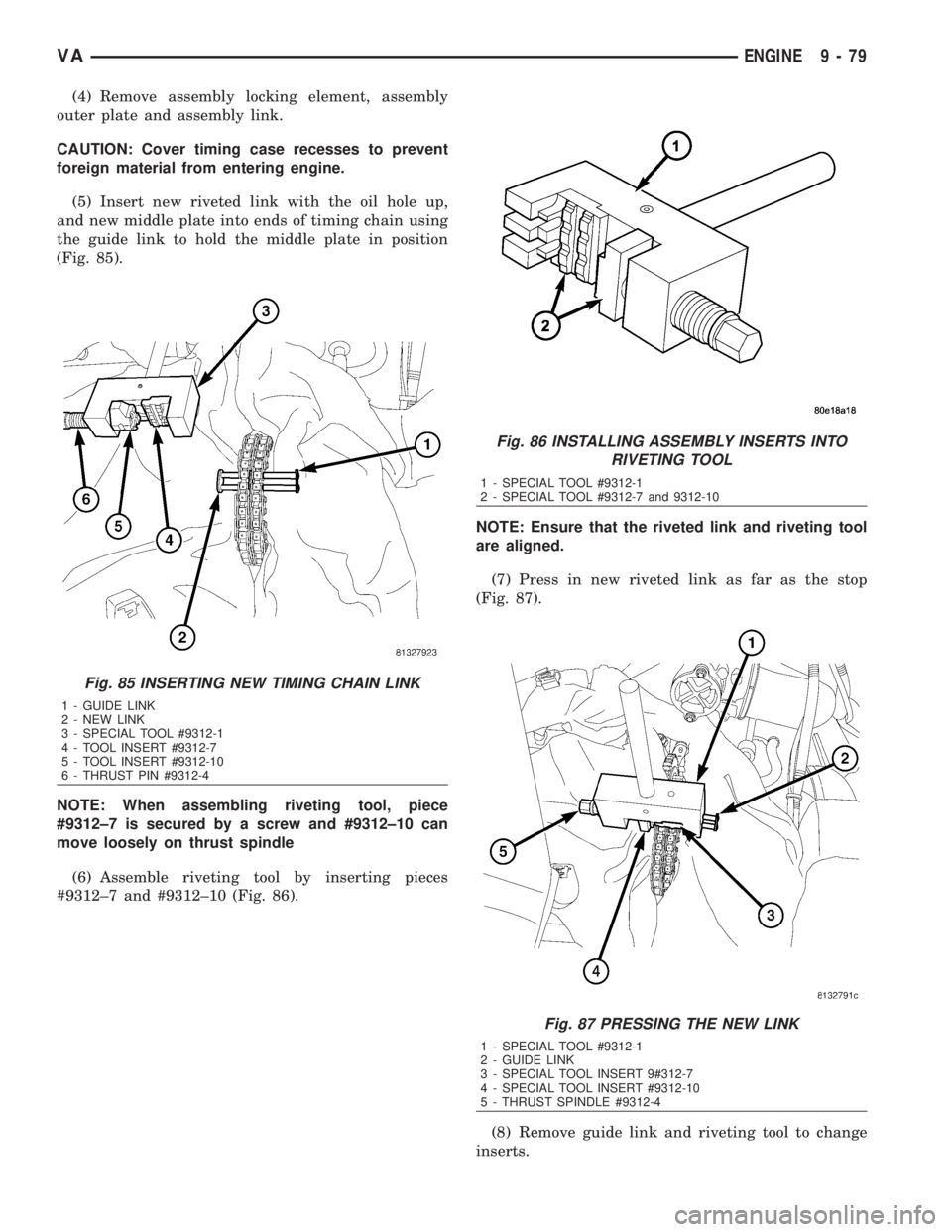
(5) Insert new riveted link with the oil hole up,
and new middle plate into ends of timing chain using
the guide link to hold the middle plate in position
(Fig. 85).
NOTE: When assembling riveting tool, piece
#9312±7 is secured by a screw and #9312±10 can
move loosely on thrust spindle
(6) Assemble riveting tool by inserting pieces
#9312±7 and #9312±10 (Fig. 86).NOTE: Ensure that the riveted link and riveting tool
are aligned.
(7) Press in new riveted link as far as the stop
(Fig. 87).
(8) Remove guide link and riveting tool to change
inserts.
Fig. 85 INSERTING NEW TIMING CHAIN LINK
1 - GUIDE LINK
2 - NEW LINK
3 - SPECIAL TOOL #9312-1
4 - TOOL INSERT #9312-7
5 - TOOL INSERT #9312-10
6 - THRUST PIN #9312-4
Fig. 86 INSTALLING ASSEMBLY INSERTS INTO
RIVETING TOOL
1 - SPECIAL TOOL #9312-1
2 - SPECIAL TOOL #9312-7 and 9312-10
Fig. 87 PRESSING THE NEW LINK
1 - SPECIAL TOOL #9312-1
2 - GUIDE LINK
3 - SPECIAL TOOL INSERT 9#312-7
4 - SPECIAL TOOL INSERT #9312-10
5 - THRUST SPINDLE #9312-4
VAENGINE 9 - 79
Page 1655 of 2305
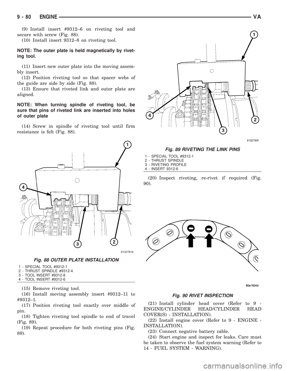
(9) Install insert #9312±6 on riveting tool and
secure with screw (Fig. 88).
(10) Install insert 9312±8 on riveting tool.
NOTE: The outer plate is held magnetically by rivet-
ing tool.
(11) Insert new outer plate into the moving assem-
bly insert.
(12) Position riveting tool so that spacer webs of
the guide are side by side (Fig. 88).
(13) Ensure that riveted link and outer plate are
aligned.
NOTE: When turning spindle of riveting tool, be
sure that pins of riveted link are inserted into holes
of outer plate
(14) Screw in spindle of riveting tool until firm
resistance is felt (Fig. 88).
(15) Remove riveting tool.
(16) Install moving assembly insert #9312±11 to
#9312±1.
(17) Position riveting tool exactly over middle of
pin.
(18) Tighten riveting tool spindle to end of travel
(Fig. 89).
(19) Repeat procedure for both riveting pins (Fig.
89).(20) Inspect riveting, re-rivet if required (Fig.
90).
(21) Install cylinder head cover (Refer to 9 -
ENGINE/CYLINDER HEAD/CYLINDER HEAD
COVER(S) - INSTALLATION).
(22) Install engine cover (Refer to 9 - ENGINE -
INSTALLATION).
(23) Connect negative battery cable.
(24) Start engine and inspect for leaks. Care must
be taken to observe the fuel system warning (Refer to
14 - FUEL SYSTEM - WARNING).
Fig. 88 OUTER PLATE INSTALLATION
1 - SPECIAL TOOL #9312-1
2 - THRUST SPINDLE #9312-4
3 - TOOL INSERT #9312-8
4 - TOOL INSERT #9312-6
Fig. 89 RIVETING THE LINK PINS
1 - SPECIAL TOOL #9312-1
2 - THRUST SPINDLE
3 - RIVETING PROFILE
4 - INSERT 9312-6
Fig. 90 RIVET INSPECTION
9 - 80 ENGINEVA
Page 1656 of 2305
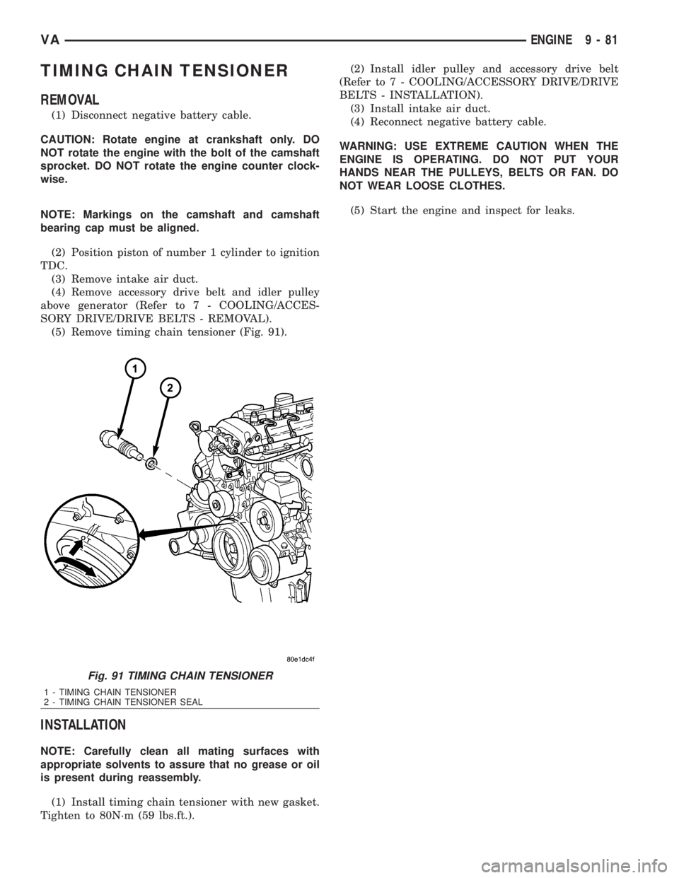
TIMING CHAIN TENSIONER
REMOVAL
(1) Disconnect negative battery cable.
CAUTION: Rotate engine at crankshaft only. DO
NOT rotate the engine with the bolt of the camshaft
sprocket. DO NOT rotate the engine counter clock-
wise.
NOTE: Markings on the camshaft and camshaft
bearing cap must be aligned.
(2) Position piston of number 1 cylinder to ignition
TDC.
(3) Remove intake air duct.
(4) Remove accessory drive belt and idler pulley
above generator (Refer to 7 - COOLING/ACCES-
SORY DRIVE/DRIVE BELTS - REMOVAL).
(5) Remove timing chain tensioner (Fig. 91).
INSTALLATION
NOTE: Carefully clean all mating surfaces with
appropriate solvents to assure that no grease or oil
is present during reassembly.
(1) Install timing chain tensioner with new gasket.
Tighten to 80N´m (59 lbs.ft.).(2) Install idler pulley and accessory drive belt
(Refer to 7 - COOLING/ACCESSORY DRIVE/DRIVE
BELTS - INSTALLATION).
(3) Install intake air duct.
(4) Reconnect negative battery cable.
WARNING: USE EXTREME CAUTION WHEN THE
ENGINE IS OPERATING. DO NOT PUT YOUR
HANDS NEAR THE PULLEYS, BELTS OR FAN. DO
NOT WEAR LOOSE CLOTHES.
(5) Start the engine and inspect for leaks.
Fig. 91 TIMING CHAIN TENSIONER
1 - TIMING CHAIN TENSIONER
2 - TIMING CHAIN TENSIONER SEAL
VAENGINE 9 - 81
Page 1658 of 2305
EXHAUST SYSTEM
TABLE OF CONTENTS
page page
EXHAUST SYSTEM
DESCRIPTION - 2.7L DIESEL...............1
DIAGNOSIS AND TESTING - DIESEL ENGINE . . 2
CATALYTIC CONVERTER
REMOVAL.............................3
INSTALLATION..........................3
EXHAUST PIPE
REMOVAL.............................3
INSTALLATION..........................3
TAILPIPE
REMOVAL.............................3
INSTALLATION..........................3
TURBOCHARGER SYSTEM
DESCRIPTION..........................3
OPERATION............................4
CHARGE AIR COOLER AND PLUMBING
DESCRIPTION..........................4OPERATION............................5
DIAGNOSIS AND TESTING - CHARGE AIR
COOLER SYSTEM - LEAKS...............5
REMOVAL.............................5
CLEANING.............................5
INSPECTION...........................6
INSTALLATION..........................6
TURBOCHARGER
DESCRIPTION..........................6
OPERATION............................6
REMOVAL
REMOVAL............................7
REMOVAL - VACUUM TRANSDUCER.......8
INSTALLATION
INSTALLATION........................8
INSTALLATION - VACUUM TRANSDUCER . . . 9
EXHAUST SYSTEM
DESCRIPTION - 2.7L DIESEL
CAUTION: Avoid application of rust prevention com-
pounds or undercoating materials to exhaust sys-
tem floor pan exhaust heat shields. Light overspray
near the edges is permitted. Application of coating
will result in excessive floor pan temperatures and
objectionable fumes.
The diesel engine exhaust system consists of an
engine exhaust manifold, turbocharger, exhaust pipe,
resonator, extension pipe (if needed), muffler and
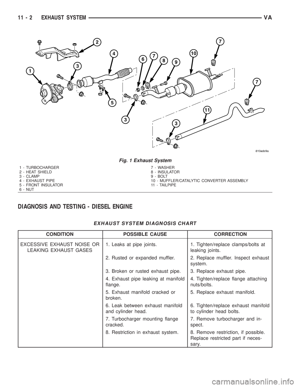
exhaust tailpipe (Fig. 1).
The exhaust system must be properly aligned and
secured to prevent stress, leakage and body contact.
The exhaust components should be kept a minimum
of 25.4 mm (1.0 in.) away from the body and frame.
If the system contacts any body panel, it may amplify
objectionable noises from the engine or body.
VAEXHAUST SYSTEM 11 - 1
Page 1659 of 2305
DIAGNOSIS AND TESTING - DIESEL ENGINE
EXHAUST SYSTEM DIAGNOSIS CHART
CONDITION POSSIBLE CAUSE CORRECTION
EXCESSIVE EXHAUST NOISE OR
LEAKING EXHAUST GASES1. Leaks at pipe joints. 1. Tighten/replace clamps/bolts at
leaking joints.
2. Rusted or expanded muffler. 2. Replace muffler. Inspect exhaust
system.
3. Broken or rusted exhaust pipe. 3. Replace exhaust pipe.
4. Exhaust pipe leaking at manifold
flange.4. Tighten/replace flange attaching
nuts/bolts.
5. Exhaust manifold cracked or
broken.5. Replace exhaust manifold.
6. Leak between exhaust manifold
and cylinder head.6. Tighten/replace exhaust manifold
to cylinder head bolts.
7. Turbocharger mounting flange
cracked.7. Remove turbocharger and in-
spect.
8. Restriction in exhaust system. 8. Remove restriction, if possible.
Replace restricted part if neces-
sary.
Fig. 1 Exhaust System
1 - TURBOCHARGER
2 - HEAT SHIELD
3 - CLAMP
4 - EXHAUST PIPE
5 - FRONT INSULATOR
6 - NUT7 - WASHER
8 - INSULATOR
9 - BOLT
10 - MUFFLER/CATALYTIC CONVERTER ASSEMBLY
11 - TAILPIPE
11 - 2 EXHAUST SYSTEMVA