2006 MERCEDES-BENZ SPRINTER engine
[x] Cancel search: enginePage 1676 of 2305
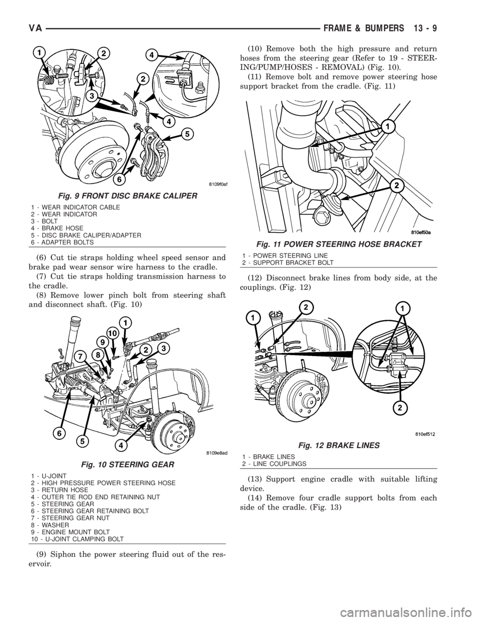
(6) Cut tie straps holding wheel speed sensor and
brake pad wear sensor wire harness to the cradle.
(7) Cut tie straps holding transmission harness to
the cradle.
(8) Remove lower pinch bolt from steering shaft
and disconnect shaft. (Fig. 10)
(9) Siphon the power steering fluid out of the res-
ervoir.(10) Remove both the high pressure and return
hoses from the steering gear (Refer to 19 - STEER-
ING/PUMP/HOSES - REMOVAL) (Fig. 10).
(11) Remove bolt and remove power steering hose
support bracket from the cradle. (Fig. 11)
(12) Disconnect brake lines from body side, at the
couplings. (Fig. 12)
(13) Support engine cradle with suitable lifting
device.
(14) Remove four cradle support bolts from each
side of the cradle. (Fig. 13)
Fig. 9 FRONT DISC BRAKE CALIPER
1 - WEAR INDICATOR CABLE
2 - WEAR INDICATOR
3 - BOLT
4 - BRAKE HOSE
5 - DISC BRAKE CALIPER/ADAPTER
6 - ADAPTER BOLTS
Fig. 10 STEERING GEAR
1 - U-JOINT
2 - HIGH PRESSURE POWER STEERING HOSE
3 - RETURN HOSE
4 - OUTER TIE ROD END RETAINING NUT
5 - STEERING GEAR
6 - STEERING GEAR RETAINING BOLT
7 - STEERING GEAR NUT
8 - WASHER
9 - ENGINE MOUNT BOLT
10 - U-JOINT CLAMPING BOLT
Fig. 11 POWER STEERING HOSE BRACKET
1 - POWER STEERING LINE
2 - SUPPORT BRACKET BOLT
Fig. 12 BRAKE LINES
1 - BRAKE LINES
2 - LINE COUPLINGS
VAFRAME & BUMPERS 13 - 9
Page 1677 of 2305
(15) Lower engine cradle.
(16) Release support clips and remove brake lines.
(17) Remove nuts and remove jounce bumpers.
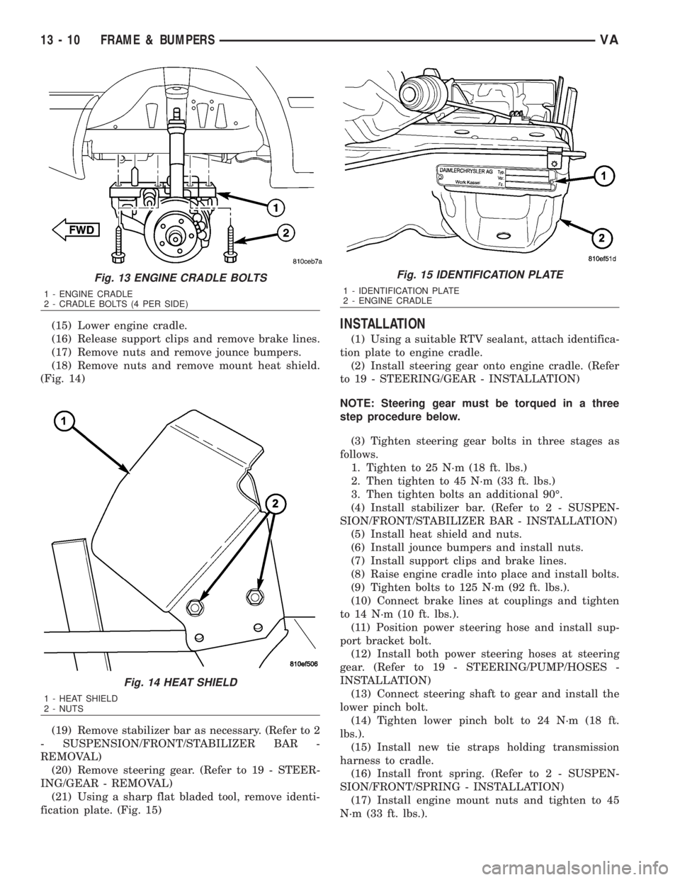
(18) Remove nuts and remove mount heat shield.
(Fig. 14)
(19) Remove stabilizer bar as necessary. (Refer to 2
- SUSPENSION/FRONT/STABILIZER BAR -
REMOVAL)
(20) Remove steering gear. (Refer to 19 - STEER-
ING/GEAR - REMOVAL)
(21) Using a sharp flat bladed tool, remove identi-
fication plate. (Fig. 15)INSTALLATION
(1) Using a suitable RTV sealant, attach identifica-
tion plate to engine cradle.
(2) Install steering gear onto engine cradle. (Refer
to 19 - STEERING/GEAR - INSTALLATION)
NOTE: Steering gear must be torqued in a three
step procedure below.
(3) Tighten steering gear bolts in three stages as
follows.
1. Tighten to 25 N´m (18 ft. lbs.)
2. Then tighten to 45 N´m (33 ft. lbs.)
3. Then tighten bolts an additional 90É.
(4) Install stabilizer bar. (Refer to 2 - SUSPEN-
SION/FRONT/STABILIZER BAR - INSTALLATION)
(5) Install heat shield and nuts.
(6) Install jounce bumpers and install nuts.
(7) Install support clips and brake lines.
(8) Raise engine cradle into place and install bolts.
(9) Tighten bolts to 125 N´m (92 ft. lbs.).
(10) Connect brake lines at couplings and tighten
to 14 N´m (10 ft. lbs.).
(11) Position power steering hose and install sup-
port bracket bolt.
(12) Install both power steering hoses at steering
gear. (Refer to 19 - STEERING/PUMP/HOSES -
INSTALLATION)
(13) Connect steering shaft to gear and install the
lower pinch bolt.
(14) Tighten lower pinch bolt to 24 N´m (18 ft.
lbs.).
(15) Install new tie straps holding transmission
harness to cradle.
(16) Install front spring. (Refer to 2 - SUSPEN-
SION/FRONT/SPRING - INSTALLATION)
(17) Install engine mount nuts and tighten to 45
N´m (33 ft. lbs.).
Fig. 13 ENGINE CRADLE BOLTS
1 - ENGINE CRADLE
2 - CRADLE BOLTS (4 PER SIDE)
Fig. 14 HEAT SHIELD
1 - HEAT SHIELD
2 - NUTS
Fig. 15 IDENTIFICATION PLATE
1 - IDENTIFICATION PLATE
2 - ENGINE CRADLE
13 - 10 FRAME & BUMPERSVA
Page 1682 of 2305
FUEL SYSTEM
TABLE OF CONTENTS
page page
FUEL SYSTEM
WARNING
WARNING - HIGH FUEL SYSTEM
PRESSURE...........................1
WARNING............................1
DIAGNOSIS AND TESTING
DIAGNOSIS AND TESTING - HIGH
PRESSURE FUEL LINES.................1
DIAGNOSIS AND TESTING - AIR IN FUEL
SYSTEM.............................2
DIAGNOSIS AND TESTING - INJECTOR
LEAK QUANTITY.......................2STANDARD PROCEDURE
STANDARD PROCEDURES - CLEANING
FUEL SYSTEM COMPONENTS............3
STANDARD PROCEDURES - DRAINING
WATER FROM FUEL FILTER..............3
STANDARD PROCEDURE - LOW
PRESSURE FUEL PUMP TEST............4
FUEL DELIVERY..........................6
FUEL INJECTION........................31
FUEL SYSTEM
WARNING
WARNING - HIGH FUEL SYSTEM PRESSURE
WARNING: HIGH-PRESSURE FUEL LINES DELIVER
FUEL UNDER EXTREME PRESSURE FROM THE
INJECTION PUMP TO THE INJECTORS. THIS
MAYBE AS HIGH AS 1600BAR (23,200PSI). USE
EXTREME CAUTION WHEN INSPECTING FOR HIGH-
PRESSURE FUEL LEAKS. FUEL UNDER THIS
AMOUNT OF PRESSURE CAN PENETRATE SKIN
CAUSING PERSONAL INJURY OR DEATH. INSPECT
FOR HIGH-PRESSURE FUEL LEAKS WITH A SHEET
OF CARDBOARD PLACED IN THE SUSPECTED
AREA WHILE THE ENGINE IS NOT RUNNING.
START THE VEHICLE AND ALLOW THE ENGINE TO
RUN FOR A SHORT PERIOD. TURN THE ENGINE
OFF AND INSPECT THE PIECE OF CARDBOARD.
WEAR SAFETY GOGGLES AND ADEQUATE PRO-
TECTIVE CLOTHING WHEN SERVICING FUEL SYS-
TEM.
WARNING
WARNING: UNDER NO CIRCUMSTANCES SHOULD
GASOLINE BE MIXED WITH DIESEL FUEL (NOT
EVEN DURING WINTER). THE HIGH PRESSURE
PUMP IS LUBRICATED BY DIESEL FUEL. IMMEDI-
ATE FUEL SYSTEM DAMAGE MAY OCCUR CAUS-
ING REPLACEMENT AND FLUSHING OF THE
COMPLETE DIESEL FUEL SYSTEM. HIGH PRES-
SURE PUMP SEIZURE WILL CAUSE METAL PARTI-
CLES TO SPREAD THROUGH OUT THE FUELCIRCUIT. ALL CDI FUEL SYSTEM COMPONENTS
CONNECTED TO THE FUEL CIRCUIT WILL HAVE TO
BE EXCHANGED AND THE LINES FLUSHED.
DIAGNOSIS AND TESTING
DIAGNOSIS AND TESTING - HIGH PRESSURE
FUEL LINES
WARNING: HIGH-PRESSURE FUEL LINES DELIVER
FUEL UNDER EXTREME PRESSURE FROM THE
INJECTION PUMP TO THE INJECTORS. THIS
MAYBE AS HIGH AS 1600BAR (23,200PSI). USE
EXTREME CAUTION WHEN INSPECTING FOR HIGH-
PRESSURE FUEL LEAKS. FUEL UNDER THIS
AMOUNT OF PRESSURE CAN PENETRATE SKIN
CAUSING PERSONAL INJURY OR DEATH. INSPECT
FOR HIGH-PRESSURE FUEL LEAKS WITH A SHEET
OF CARDBOARD PLACED IN THE SUSPECTED
AREA WHILE THE ENGINE IS NOT RUNNING.
START THE VEHICLE AND ALLOW THE ENGINE TO
RUN FOR A SHORT PERIOD. TURN THE ENGINE
OFF AND INSPECT THE PIECE OF CARDBOARD.
WEAR SAFETY GOGGLES AND ADEQUATE PRO-
TECTIVE CLOTHING WHEN SERVICING FUEL SYS-
TEM.
High-pressure fuel line leaks can cause starting
problems and poor engine performance.
²Turn the engine off.
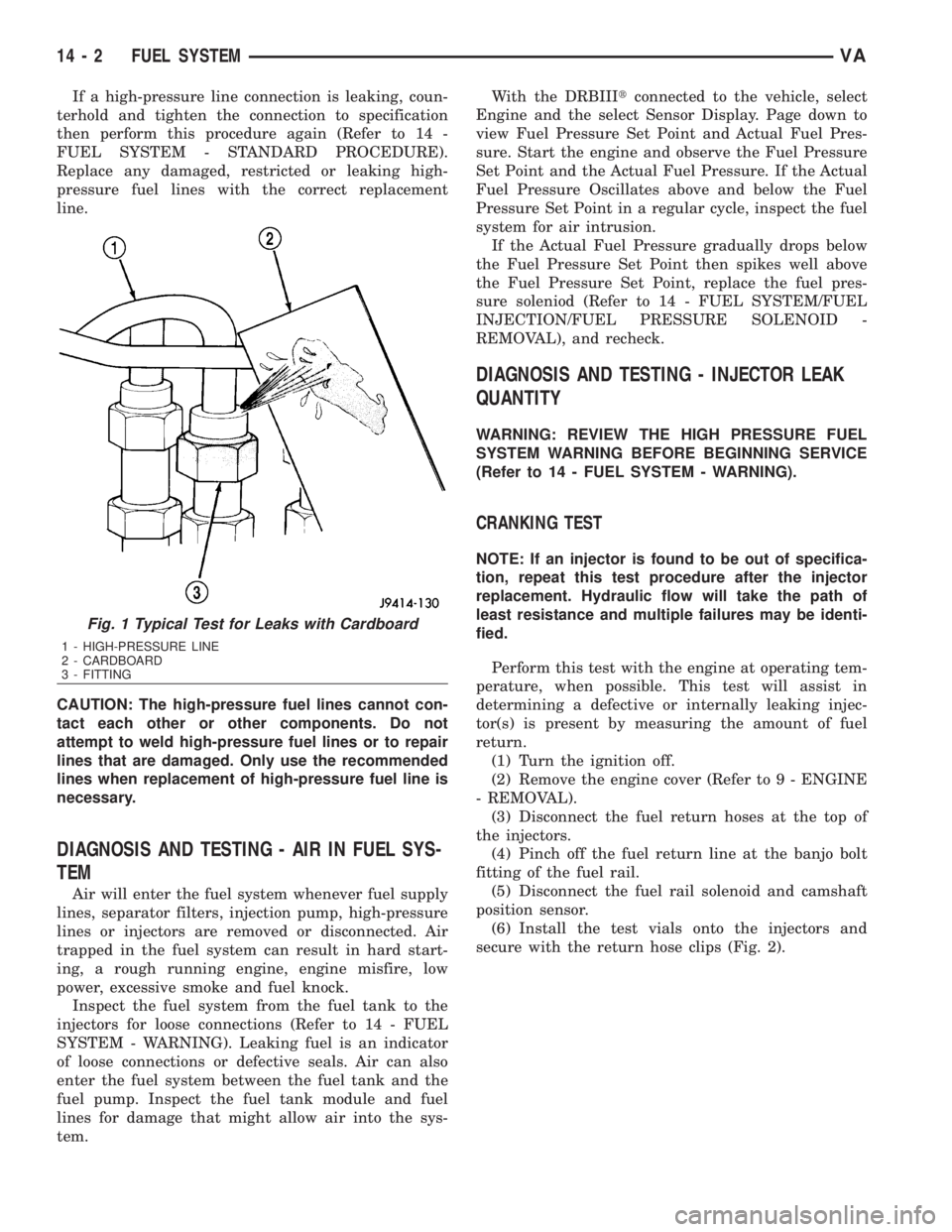
²Place a piece for cardboard in the suspected area
(Fig. 1).
²Start the engine and allow to run for a short
period.
²Turn the engine off.
²Inspect the cardboard.
VAFUEL SYSTEM 14 - 1
Page 1683 of 2305
If a high-pressure line connection is leaking, coun-
terhold and tighten the connection to specification
then perform this procedure again (Refer to 14 -
FUEL SYSTEM - STANDARD PROCEDURE).
Replace any damaged, restricted or leaking high-
pressure fuel lines with the correct replacement
line.
CAUTION: The high-pressure fuel lines cannot con-
tact each other or other components. Do not
attempt to weld high-pressure fuel lines or to repair
lines that are damaged. Only use the recommended
lines when replacement of high-pressure fuel line is
necessary.
DIAGNOSIS AND TESTING - AIR IN FUEL SYS-
TEM
Air will enter the fuel system whenever fuel supply
lines, separator filters, injection pump, high-pressure
lines or injectors are removed or disconnected. Air
trapped in the fuel system can result in hard start-
ing, a rough running engine, engine misfire, low
power, excessive smoke and fuel knock.
Inspect the fuel system from the fuel tank to the
injectors for loose connections (Refer to 14 - FUEL
SYSTEM - WARNING). Leaking fuel is an indicator
of loose connections or defective seals. Air can also
enter the fuel system between the fuel tank and the
fuel pump. Inspect the fuel tank module and fuel
lines for damage that might allow air into the sys-
tem.With the DRBIIItconnected to the vehicle, select
Engine and the select Sensor Display. Page down to
view Fuel Pressure Set Point and Actual Fuel Pres-
sure. Start the engine and observe the Fuel Pressure
Set Point and the Actual Fuel Pressure. If the Actual
Fuel Pressure Oscillates above and below the Fuel
Pressure Set Point in a regular cycle, inspect the fuel
system for air intrusion.
If the Actual Fuel Pressure gradually drops below
the Fuel Pressure Set Point then spikes well above
the Fuel Pressure Set Point, replace the fuel pres-
sure soleniod (Refer to 14 - FUEL SYSTEM/FUEL
INJECTION/FUEL PRESSURE SOLENOID -
REMOVAL), and recheck.
DIAGNOSIS AND TESTING - INJECTOR LEAK
QUANTITY
WARNING: REVIEW THE HIGH PRESSURE FUEL
SYSTEM WARNING BEFORE BEGINNING SERVICE
(Refer to 14 - FUEL SYSTEM - WARNING).
CRANKING TEST
NOTE: If an injector is found to be out of specifica-
tion, repeat this test procedure after the injector
replacement. Hydraulic flow will take the path of
least resistance and multiple failures may be identi-
fied.
Perform this test with the engine at operating tem-
perature, when possible. This test will assist in
determining a defective or internally leaking injec-
tor(s) is present by measuring the amount of fuel
return.
(1) Turn the ignition off.
(2) Remove the engine cover (Refer to 9 - ENGINE
- REMOVAL).
(3) Disconnect the fuel return hoses at the top of
the injectors.
(4) Pinch off the fuel return line at the banjo bolt
fitting of the fuel rail.
(5) Disconnect the fuel rail solenoid and camshaft
position sensor.
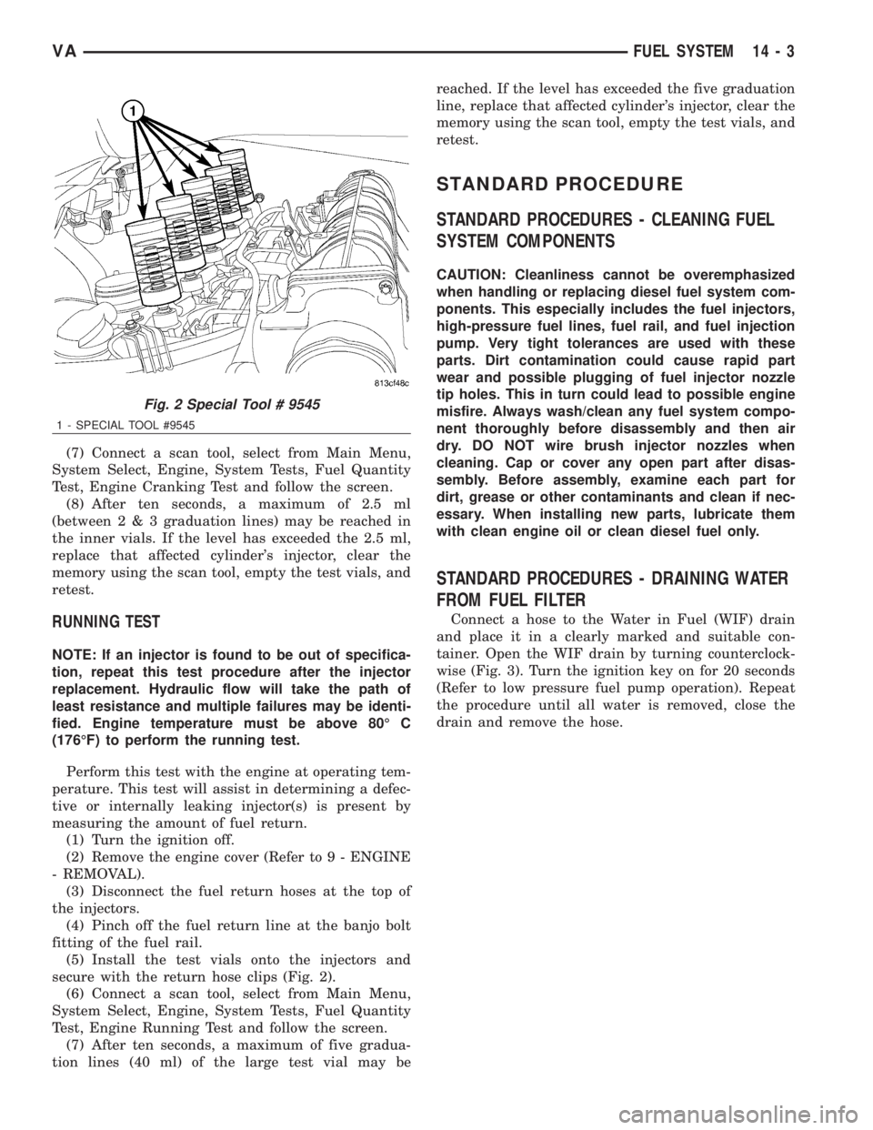
(6) Install the test vials onto the injectors and
secure with the return hose clips (Fig. 2).
Fig. 1 Typical Test for Leaks with Cardboard
1 - HIGH-PRESSURE LINE
2 - CARDBOARD
3 - FITTING
14 - 2 FUEL SYSTEMVA
Page 1684 of 2305
(7) Connect a scan tool, select from Main Menu,
System Select, Engine, System Tests, Fuel Quantity
Test, Engine Cranking Test and follow the screen.
(8) After ten seconds, a maximum of 2.5 ml
(between2&3graduation lines) may be reached in
the inner vials. If the level has exceeded the 2.5 ml,
replace that affected cylinder's injector, clear the
memory using the scan tool, empty the test vials, and
retest.
RUNNING TEST
NOTE: If an injector is found to be out of specifica-
tion, repeat this test procedure after the injector
replacement. Hydraulic flow will take the path of
least resistance and multiple failures may be identi-
fied. Engine temperature must be above 80É C
(176ÉF) to perform the running test.
Perform this test with the engine at operating tem-
perature. This test will assist in determining a defec-
tive or internally leaking injector(s) is present by
measuring the amount of fuel return.
(1) Turn the ignition off.
(2) Remove the engine cover (Refer to 9 - ENGINE
- REMOVAL).
(3) Disconnect the fuel return hoses at the top of
the injectors.
(4) Pinch off the fuel return line at the banjo bolt
fitting of the fuel rail.
(5) Install the test vials onto the injectors and
secure with the return hose clips (Fig. 2).
(6) Connect a scan tool, select from Main Menu,
System Select, Engine, System Tests, Fuel Quantity
Test, Engine Running Test and follow the screen.
(7) After ten seconds, a maximum of five gradua-
tion lines (40 ml) of the large test vial may bereached. If the level has exceeded the five graduation
line, replace that affected cylinder's injector, clear the
memory using the scan tool, empty the test vials, and
retest.
STANDARD PROCEDURE
STANDARD PROCEDURES - CLEANING FUEL
SYSTEM COMPONENTS
CAUTION: Cleanliness cannot be overemphasized
when handling or replacing diesel fuel system com-
ponents. This especially includes the fuel injectors,
high-pressure fuel lines, fuel rail, and fuel injection
pump. Very tight tolerances are used with these
parts. Dirt contamination could cause rapid part
wear and possible plugging of fuel injector nozzle
tip holes. This in turn could lead to possible engine
misfire. Always wash/clean any fuel system compo-
nent thoroughly before disassembly and then air
dry. DO NOT wire brush injector nozzles when
cleaning. Cap or cover any open part after disas-
sembly. Before assembly, examine each part for
dirt, grease or other contaminants and clean if nec-
essary. When installing new parts, lubricate them
with clean engine oil or clean diesel fuel only.
STANDARD PROCEDURES - DRAINING WATER
FROM FUEL FILTER
Connect a hose to the Water in Fuel (WIF) drain
and place it in a clearly marked and suitable con-
tainer. Open the WIF drain by turning counterclock-
wise (Fig. 3). Turn the ignition key on for 20 seconds
(Refer to low pressure fuel pump operation). Repeat
the procedure until all water is removed, close the
drain and remove the hose.
Fig. 2 Special Tool # 9545
1 - SPECIAL TOOL #9545
VAFUEL SYSTEM 14 - 3
Page 1688 of 2305
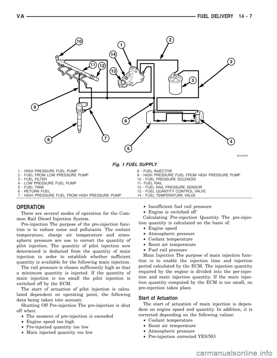
OPERATION
There are several modes of operation for the Com-
mon Rail Diesel Injection System.
Pre-injection The purpose of the pre-injection func-
tion is to reduce noise and pollutants. The coolant
temperature, charge air temperature and atmo-
spheric pressure are use to correct the quantity of
pilot injection. The quantity of pilot injection now
determined is deducted from the quantity of main
injection in order to establish whether sufficient
quantity is available for the following main injection.
The rail pressure is chosen sufficiently high so that
a minimum quantity is injected. If the quantity of
main injection is too small the pilot injection is
switched off by the ECM.
The start of actuation of pilot injection is calcu-
lated dependent on operating point, the following
data being taken into account:
Shutting Off Pre-injection The pre-injection is shut
off when:
²The moment of pre-injection is exceeded
²Engine speed too high
²Pre-injected quantity too low
²Main injected quantity too low²Insufficient fuel rail pressure
²Engine is switched off
Calculating Pre-injection Quantity The pre-injec-
tion quantity is calculated on the basis of:
²Engine speed
²Atmospheric pressure
²Coolant temperature
²Boost air temperature
²Fuel rail pressure
Main Injection The purpose of main injection func-
tion is to enable the injection time and injection
period calculated by the ECM. The injection quantity
required by the engine is divided into the per-injec-
tion and main injection quantity. If the main injec-
tion quantity computed by the ECM is too small, no
pre-injection takes place.
Start of Actuation
The start of actuation of main injection is depen-
dent on engine speed and quantity. In addition, it is
corrected depending on the following values:
²Coolant temperature
²Boost air temperature
²Atmospheric pressure
²Pre-injection corrected YES/NO
Fig. 1 FUEL SUPPLY
1 - HIGH PRESSURE FUEL PUMP 8 - FUEL INJECTOR
2 - FUEL FROM LOW PRESSURE PUMP 9 - HIGH PRESSURE FUEL FROM HIGH PRESSURE PUMP
3 - FUEL FILTER 10 - FUEL PRESSURE SOLENOID
4 - LOW PRESSURE FUEL PUMP 11- FUEL RAIL
5 - FUEL TANK 12 - FUEL RAIL PRESSURE SENSOR
6 - RETURN FUEL 13 - FUEL QUANTITY CONTROL VALVE
7 - HIGH PRESSURE FUEL FROM HIGH PRESSURE PUMP 14 - FUEL TEMPERATURE VALVE
VAFUEL DELIVERY 14 - 7
Page 1689 of 2305
Switching Off Main Injection
Main injection is switched off when:
²Engine speed is too high >4700 - 4800 rpm
²Main injection quantity too low
²Low fuel pressure in fuel rail
²Engine off
²External quantity control
²Deceleration mode
Calculating Main Injection
The quantity of main injection is calculated by:
²Engine speed
²Atmospheric pressure
²Coolant temperature
²Boost air temperature
²Fuel rail pressure
²Boost pressure
Period of Actuation
For calculating the period of actuation of the main
injection it is necessary to know whether a pre-injec-
tion has occurred or not.
The coolant temperature, charge air temperature
and the atmospheric pressure are used for correcting
the main injection quantity. If main injection quan-
tity is less than a minimum quantity which is depen-
dent on fuel rail pressure, no preinjection takes
place. In this case, only main injection is performed.
If the quantity is then still below the minimum
quantity, neither main injection or pre-injection takes
place (deceleration mode).
Deceleration Mode
The purpose of the deceleration mode is to inter-
rupt the operation of the injectors. The ECM deter-
mines the accelerator pedal position from a supplied
signal and it determines the engine speed by the
crank sensor. In the overrun and with the engine
speed above 1600, with the accelerator pedal no
pressed, the injectors are no longer actuated and the
fuel rail pressure is lowered by the pressure regula-
tor valve.
Full Load Injected Quantity
The purpose of the full load injected quantity is to
minimize the formation of smoke. The ECM limits
the fuel rail pressure when the engine is operating at
full load by way of the quantity control valve, and
quantity of fuel injected by the injectors. this mini-
mizes the formation of smoke when accelerating and
driving at constant speeds. If a fault occurs at the
boost pressure control, full load injected quantity is
reduced.
Limiting Maximum Engine Speed
The ECM determines the engine speed based on
the signal supplied by the crankshaft sensor and lim-its this by interrupting the operation of the fuel
injectors.
Fuel Quantity Control
The fuel quantity is controlled separately for each
cylinder by the ECM inline with the firing order.The
ECM detects the operating state which exists at the
engine by means of the sensors. In order adapt the
quantity injected, either the fuel rail pressure can be
adjusted by the fuel solenoid and quantity control
valve or the actuation time of the solenoid valves in
the injectors
Boiling Protection
In order to protect against thermal overload and
along with criteria programmed in the ECM, the
injection quantity is reduced as a function of the cool-
ant temperature and vehicle speed. If the coolant
temperature sensor fails the oil temperature signal
from the oil sensor is used as a suitable value.
Fuel Tank Protection
The fuel rail pressure is lowered in order to protect
the fuel tank from overheating. The fuel temperature
sensor measures the temperature of the fuel being
supplied from the tank, in the high pressure flange.
If the fuel is too warm the fuel rail pressure is fur-
ther reduced by the quantity control valve.
STANDARD PROCEDURE
STANDARD PROCEDURE - DRAINING FUEL
TANK - DIESEL
(1) Position a drain hose into the fuel fill opening.
(2) Drain fuel tank using an approved diesel fuel
draining station.
FUEL CONTAMINATION
If a diesel engine's fuel supply has been contami-
nated with gasoline, the following procedure must be
followed:
(1) Remove all fuel from the fuel tank. (Refer to 14
- FUEL SYSTEM/FUEL DELIVERY - STANDARD
PROCEDURE-DRAINING FUEL TANK) Use an
appropriate fuel container. Dispose of the contami-
nated fuel using the proper procedures.
CAUTION: Dispose of petroleum based products in
a manner consistent with all applicable Local, State,
Federal, and Provincial regulations.
(2) Remove and clean fuel tank. (Refer to 14 -
FUEL SYSTEM/FUEL DELIVERY/FUEL TANK -
REMOVAL)
(3) Install the fuel tank. (Refer to 14 - FUEL SYS-
TEM/FUEL DELIVERY/FUEL TANK - INSTALLA-
TION)
14 - 8 FUEL DELIVERYVA
Page 1690 of 2305
(4) Fill fuel tank with fresh diesel fuel.
(5) Drain and remove the fuel filter. (Refer to 14 -
FUEL SYSTEM/FUEL DELIVERY/FUEL FILTER /
WATER SEPARATOR - REMOVAL)
(6) Install a new fuel filter. (Refer to 14 - FUEL
SYSTEM/FUEL DELIVERY/FUEL FILTER / WATER
SEPARATOR - INSTALLATION)
(7) Check the engine control module for any diag-
nostic trouble codes (DTCs). Record and clear any
DTCs that are present.
(8) Start and run the engine. Run the engine for
up to 15 minutes to allow time for any DTCs to reset
and shut off the engine.
(9) Check the engine control module for any diag-
nostic trouble codes (DTCs). Record any DTCs that
are present. Refer to the appropriate engine electrical
diagnostics to diagnose any DTCs that were set.
CAUTION: With the high pressure fuel system in
this vehicle, any residual contaminated fuel will be
removed very quickly. Shut off the engine immedi-
ately if signs of engine damage are noted.The engine should then be evaluated to determine
if the contaminated fuel has caused any damage to
the fuel system and/or engine. Indicators that the
fuel system has been damaged include the following:
²Unstable fuel rail pressure. This can manifest
itself as instability of idle speeds, excessive under-
shoot/overshoot at engine start-up, or excessive
undershoot/overshoot when the engine operating con-
ditions change. A typical engine response to a large
rail pressure undershoot would be a decrease in
engine speed or engine stall.
²Excessive noise from the engine. This could indi-
cate poor rail pressure control or the inability of the
injection system to inject the proper amount of fuel.
²Excessive smoke (black or white). This could
indicate the inability of the fuel system to inject the
proper amount of fuel.
NOTE: If any of these conditions are exhibited after
cleaning the fuel system, proceed to the appropri-
ate engine electrical diagnostic information. Repair
the fuel system and/or engine as necessary.
SPECIFICATIONS
TORQUE
DESCRIPTION N´m Ft. Lbs. In. Lbs.
FUEL TANK MOUNTING NUTS 15 - 17 11 - 13 -
FUEL TANK MODULE LOCKRING (LOCK-
NUT)60 44 -
PRESSURE CONTROL VALVE NUT TO
FUEL RAIL (2 STAGES)60, loosen 90É, re-
tighten to 8044, loosen 90É, re-
tighten to 59-
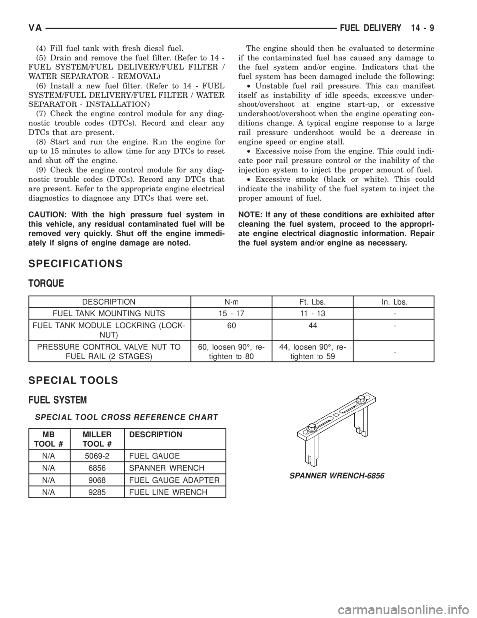
SPECIAL TOOLS
FUEL SYSTEM
SPECIAL TOOL CROSS REFERENCE CHART
MB
TOOL #MILLER
TOOL #DESCRIPTION
N/A 5069-2 FUEL GAUGE
N/A 6856 SPANNER WRENCH
N/A 9068 FUEL GAUGE ADAPTER
N/A 9285 FUEL LINE WRENCH
SPANNER WRENCH-6856
VAFUEL DELIVERY 14 - 9