Page 1703 of 2305

FUEL RAIL
DESCRIPTION
The fuel rail acts like a high pressure store. It is
available to all injectors for drawing fuel which has
been compressed by the high pressure injection
pump. The rail pressure sensor, rail pressure control
valve, high pressure line, and the return flow line
are attached to the fuel rail.
OPERATION
The stored fuel volume inside the rail acts as a
damper for pressure fluctuations which result
because of pulsating supply and brief large extrac-
tions of fuel during injector firing. The rail primarily
influences the atomization of fuel at the injector noz-
zle, and the accuracy of injected quantity during
injection.
REMOVAL
(Refer to 14 - FUEL SYSTEM - WARNING).
WARNING: NO SPARKS, OPEN FLAMES OR SMOK-
ING. RISK OF POISONING FROM INHALING AND
SWALLOWING FUEL. RISK OF INJURY TO EYES
AND SKIN FROM CONTACT WITH FUEL. POUR
FUELS ONLY INTO SUITABLE AND APPROPRI-
ATELY MARKED CONTAINERS. WEAR PROTECTIVE
CLOTHING.
(1) Disconnect negative battery cable.
(2) Remove the engine cover.
(3) Disconnect the intake manifold air inlet duct
and position aside.
(4) Disconnect the fuel rail pressure and control
valve wiring harness connectors.
(5) Remove engine harness retaining bolts and
unclip the engine harness from the fuel rail.
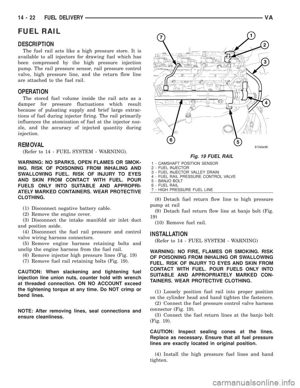
(6) Remove injector high pressure lines (Fig. 19)
(7) Remove fuel rail retaining bolts (Fig. 19).
CAUTION: When slackening and tightening fuel
injection line union nuts, counter hold with wrench
at threaded connection. ON NO ACCOUNT exceed
the tightening torque at any time. Do NOT crimp or
bend lines.
NOTE: After removing lines, seal connections and
ensure cleanliness.(8) Detach fuel return flow line to high pressure
pump at rail
(9) Detach fuel return flow line at banjo bolt (Fig.
19)
(10) Remove fuel rail.
INSTALLATION
(Refer to 14 - FUEL SYSTEM - WARNING)
WARNING: NO FIRE, FLAMES OR SMOKING. RISK
OF POISONING FROM INHALING OR SWALLOWING
FUEL. RISK OF INJURY TO EYES AND SKIN FROM
CONTACT WITH FUEL. POUR FUELS ONLY INTO
SUITABLE AND APPROPRIATELY MARKED CON-
TAINERS. WEAR PROTECTIVE CLOTHING.
(1) Loosely position fuel rail into proper position
on the cylinder head and hand tighten the fasteners.
(2) Connect the fuel pressure control valve harness
connector (Fig. 19).
(3) Connect the fuel return lines at the banjo bolt
(Fig. 19).
CAUTION: Inspect sealing cones at the lines.
Replace as necessary. Ensure that all fuel pressure
lines are exactly located in original position.
(4) Install the high pressure fuel lines and hand
tighten.
Fig. 19 FUEL RAIL
1 - CAMSHAFT POSITION SENSOR
2 - FUEL INJECTOR
3 - FUEL INJECTOR VALLEY DRAIN
4 - FUEL RAIL PRESSURE CONTROL VALVE
5 - BANJO BOLT
6 - FUEL RAIL
7 - HIGH PRESSURE FUEL LINE
14 - 22 FUEL DELIVERYVA
Page 1704 of 2305

(5) Tighten fuel rail bolts to 14 N´m (124 in. lbs.)
(Fig. 19)
CAUTION: When tightening fuel injection line union
nuts, counter hold with a wrench at the thread con-
nection. ON NO ACCOUNT exceed the tightening
torque at any time.
(6) Tighten the pressure line to the fuel rail to 20
N´m (177 in. lbs.).
(7) Tighten the high pressure fuel lines at the fuel
rail to 22 N´m (195 in. lbs.).
(8) Reconnect engine harness electrical connectors.
(9) Connect the intake manifold air inlet duct.
(10) Connect negative battery cable.
CAUTION: Care must be taken when installing the
engine cover. Assure the proper routing of the fuel
injector return fuel hose to the banjo bolt fitting in
the left rear corner of the cover. Failure to do so
may pinch or damage the hose causing fuel leakage
or a driveability concern.
WARNING: USE EXTREME CAUTION WHEN THE
ENGINE IS OPERATING. DO NOT STAND IN A
DIRECT LINE WITH FAN. DO NOT PUT YOUR
HANDS NEAR PULLEYS, BELTS OR FAN. DO NOT
WEAR LOOSE CLOTHING.
(11) Start engine, run for a few minutes, turn the
engine off and inspect for leaks (Refer to 14 - FUEL
SYSTEM - WARNING).
FUEL TANK
DESCRIPTION
The plastic fuel tank (Fig. 20) is mounted to the
frame rails under the left/center side of the vehicle.
The fuel tank contains a serviceable fuel pump mod-
ule with an electric fuel pump, and a fuel level send-
ing unit. The tank is also equipped with 2 fuel lines:
a fuel supply line to the fuel pump, and a separate
fuel return line.
Fuel Temperature Control:A section of the fuel
return line is coiled at the rear section of the tank
(Fig. 21). This coiled section is used to help drop the
temperature of fuel returning to the tank. A thermo-
stat (preheating valve) (3) (Fig. 21) is used to keep
fuel temperature below 167 degrees F. If fuel temper-
ature is above 167 degrees F, fuel passes first
through the coiled cooler lines, and then into the fuel
tank. If fuel temperature is below 150 degrees F, fuel
bypasses the coiled cooler lines, and is returned
directly into the fuel tank.
An electric fuel pump (more commonly referred to
in diesel applications as a fuel transfer pump or fuel
lift pump) is attached to the fuel pump module. Thismodule (Fig. 22) is located in the fuel tank. Refer to
Fuel Pump Module for additional information.
VAFUEL DELIVERY 14 - 23
Page 1705 of 2305
Fig. 20 FUEL TANK ASSEMBLY
1 - Strap Bolts (2)
2 - Hose (not with all engines)
3 - Fuel Outlet Line
4 - Fuel Return Line
5 - Plug
6 - Fuel Tank
7 - Tank Straps (2)8 - Nuts (2)
9 - Filler Tube
10 - Vent Hose
11 - Hose
12 - Clamps
13 - Cushioning Material
14 - Two-Way Valve
Fig. 21 FUEL COOLER LINES
1 - Expansion Tank
2-TopofTank
3 - Thermostat (Preheating Valve)
4 - Cooler Lines
5 - Connecting Hoses/Clamps
14 - 24 FUEL DELIVERYVA
Page 1707 of 2305
INSTALLATION
(1) If fuel cooler lines (Fig. 27) are to be installed,
use special pliers #9539 (Fig. 28).
(2) If fuel tank is to be replaced, install fuel pump
module into tank. Refer to Fuel Pump Module
Removal/Installation procedures.
(3) Position fuel tank to hydraulic jack.
(4) Raise tank until positioned near body.
Fig. 23 FUEL TANK ASSEMBLY
1 - Strap Bolts (2)
2 - Hose (not with all engines)
3 - Fuel Outlet Line
4 - Fuel Return Line
5 - Plug
6 - Fuel Tank
7 - Tank Straps (2)8 - Nuts (2)
9 - Filler Tube
10 - Vent Hose
11 - Hose
12 - Clamps
13 - Cushioning Material
14 - Two-Way Valve
Fig. 24 FUEL COOLER LINES
1 - Expansion Tank
2-TopofTank
3 - Thermostat (Preheating Valve)
4 - Cooler Lines
5 - Connecting Hoses/Clamps
Fig. 25 FUEL LINE PLIERS-9539
14 - 26 FUEL DELIVERYVA
Page 1708 of 2305
(5) Connect fuel pump module electrical connector
at top of tank.
(6) Connect fuel supply and return lines.
(7) Continue raising tank while guiding fill hose
into body. Raise tank until positioned snug to body.
(8) Install and position both fuel tank support
straps (7) (Fig. 26) to mounting bolts (1).
(9) Install 2 fuel tank strap nuts (8). Refer to
Torque Specifications.
(10) Remove hydraulic jack.
(11) Connect fill and vent hoses to body. Install
ground wire to fill hose.
(12) Lower vehicle.
(13) Fill fuel tank with fuel.
(14) Start engine and check for fuel leaks near top
of module.
VAFUEL DELIVERY 14 - 27
Page 1709 of 2305
FUEL LEVEL SENDING UNIT /
SENSOR
DESCRIPTION
The fuel gauge sending unit (fuel level sensor) is
attached to the side of the fuel pump module (Fig.
29). The sending unit consists of a float, an arm, and
Fig. 26 FUEL TANK ASSEMBLY
1 - Strap Bolts (2)
2 - Hose (not with all engines)
3 - Fuel Outlet Line
4 - Fuel Return Line
5 - Plug
6 - Fuel Tank
7 - Tank Straps (2)8 - Nuts (2)
9 - Filler Tube
10 - Vent Hose
11 - Hose
12 - Clamps
13 - Cushioning Material
14 - Two-Way Valve
Fig. 27 FUEL COOLER LINES
1 - Expansion Tank
2-TopofTank
3 - Thermostat (Preheating Valve)
4 - Cooler Lines
5 - Connecting Hoses/Clamps
Fig. 28 FUEL LINE PLIERS-9539
14 - 28 FUEL DELIVERYVA
Page 1713 of 2305

ACCELERATOR PEDAL POSI-
TION SENSOR
DESCRIPTION
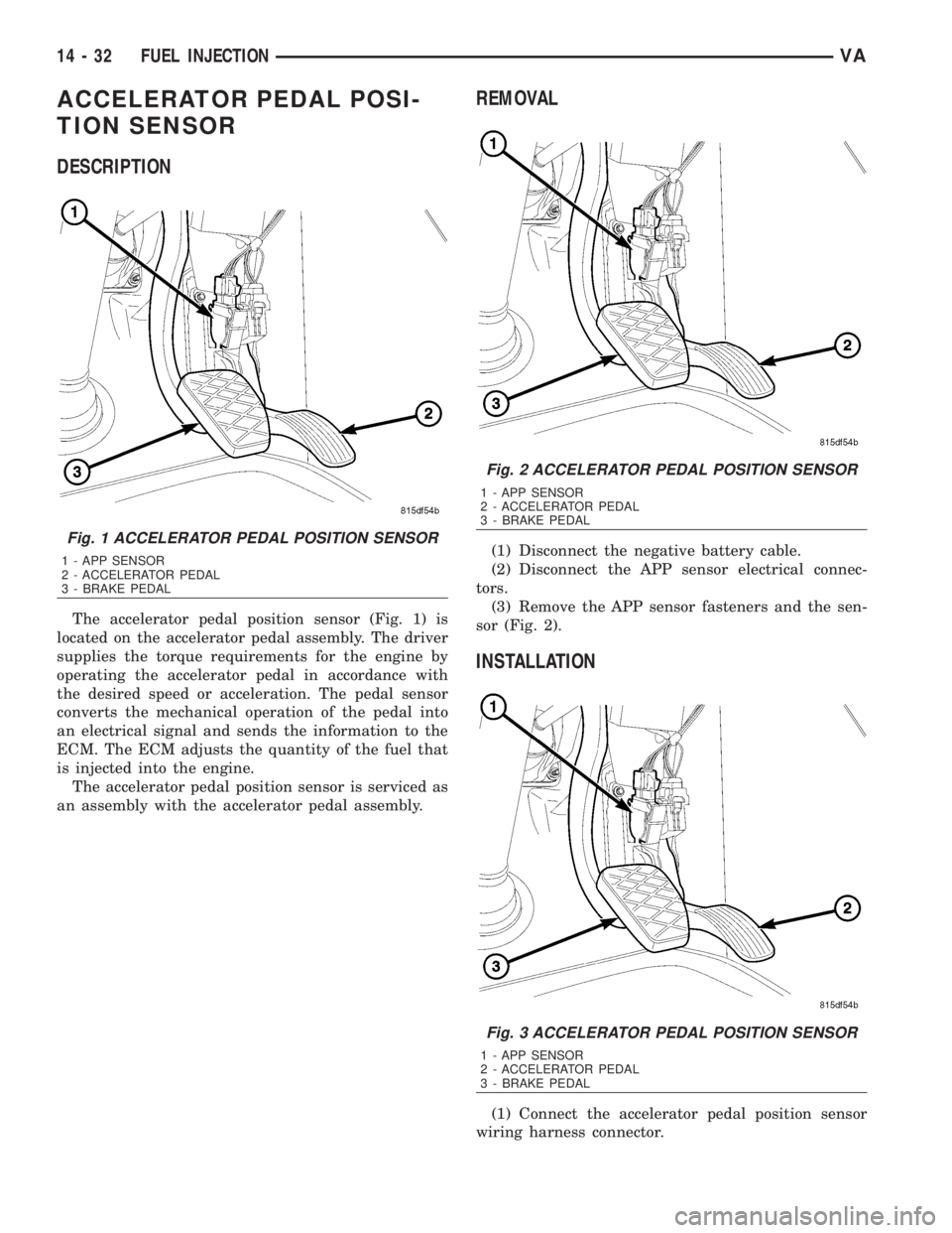
The accelerator pedal position sensor (Fig. 1) is
located on the accelerator pedal assembly. The driver
supplies the torque requirements for the engine by
operating the accelerator pedal in accordance with
the desired speed or acceleration. The pedal sensor
converts the mechanical operation of the pedal into
an electrical signal and sends the information to the
ECM. The ECM adjusts the quantity of the fuel that
is injected into the engine.
The accelerator pedal position sensor is serviced as
an assembly with the accelerator pedal assembly.
REMOVAL
(1) Disconnect the negative battery cable.
(2) Disconnect the APP sensor electrical connec-
tors.
(3) Remove the APP sensor fasteners and the sen-
sor (Fig. 2).
INSTALLATION
(1) Connect the accelerator pedal position sensor
wiring harness connector.
Fig. 1 ACCELERATOR PEDAL POSITION SENSOR
1 - APP SENSOR
2 - ACCELERATOR PEDAL
3 - BRAKE PEDAL
Fig. 2 ACCELERATOR PEDAL POSITION SENSOR
1 - APP SENSOR
2 - ACCELERATOR PEDAL
3 - BRAKE PEDAL
Fig. 3 ACCELERATOR PEDAL POSITION SENSOR
1 - APP SENSOR
2 - ACCELERATOR PEDAL
3 - BRAKE PEDAL
14 - 32 FUEL INJECTIONVA
Page 1714 of 2305

(2) Position the sensor (Fig. 3) and install the fas-
teners.
(3) Connect the negative battery cable.
BOOST PRESSURE SENSOR
DESCRIPTION
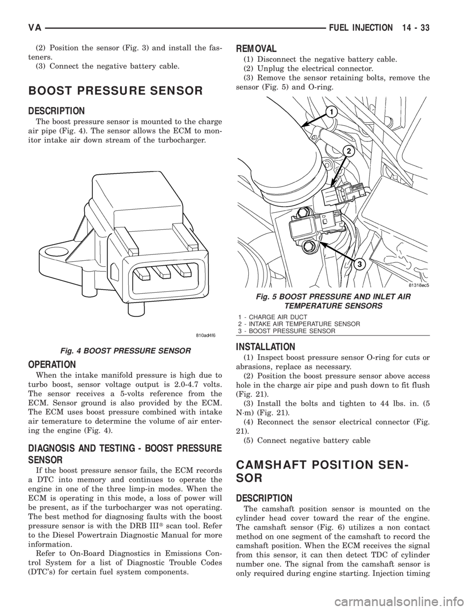
The boost pressure sensor is mounted to the charge
air pipe (Fig. 4). The sensor allows the ECM to mon-
itor intake air down stream of the turbocharger.
OPERATION
When the intake manifold pressure is high due to
turbo boost, sensor voltage output is 2.0-4.7 volts.
The sensor receives a 5-volts reference from the
ECM. Sensor ground is also provided by the ECM.
The ECM uses boost pressure combined with intake
air temerature to determine the volume of air enter-
ing the engine (Fig. 4).
DIAGNOSIS AND TESTING - BOOST PRESSURE
SENSOR
If the boost pressure sensor fails, the ECM records
a DTC into memory and continues to operate the
engine in one of the three limp-in modes. When the
ECM is operating in this mode, a loss of power will
be present, as if the turbocharger was not operating.
The best method for diagnosing faults with the boost
pressure sensor is with the DRB IIItscan tool. Refer
to the Diesel Powertrain Diagnostic Manual for more
information.
Refer to On-Board Diagnostics in Emissions Con-
trol System for a list of Diagnostic Trouble Codes
(DTC's) for certain fuel system components.
REMOVAL
(1) Disconnect the negative battery cable.
(2) Unplug the electrical connector.
(3) Remove the sensor retaining bolts, remove the
sensor (Fig. 5) and O-ring.
INSTALLATION
(1) Inspect boost pressure sensor O-ring for cuts or
abrasions, replace as necessary.
(2) Position the boost pressure sensor above access
hole in the charge air pipe and push down to fit flush
(Fig. 21).
(3) Install the bolts and tighten to 44 lbs. in. (5
N´m) (Fig. 21).
(4) Reconnect the sensor electrical connector (Fig.
21).
(5) Connect negative battery cable
CAMSHAFT POSITION SEN-
SOR
DESCRIPTION
The camshaft position sensor is mounted on the
cylinder head cover toward the rear of the engine.
The camshaft sensor (Fig. 6) utilizes a non contact
method on one segment of the camshaft to record the
camshaft position. When the ECM receives the signal
from this sensor, it can then detect TDC of cylinder
number one. The signal from the camshaft sensor is
only required during engine starting. Injection timing
Fig. 4 BOOST PRESSURE SENSOR
Fig. 5 BOOST PRESSURE AND INLET AIR
TEMPERATURE SENSORS
1 - CHARGE AIR DUCT
2 - INTAKE AIR TEMPERATURE SENSOR
3 - BOOST PRESSURE SENSOR
VAFUEL INJECTION 14 - 33