2006 MERCEDES-BENZ SPRINTER steering wheel
[x] Cancel search: steering wheelPage 392 of 2305

TEST ACTION APPLICABILITY
3 The condition that set this DTC is not present at this time.
Monitor the DRBIIItwhile wiggle testing the related harness and connectors. Look
for any related parameters to change or for the DTC to reset.
Inspect the related harness and connectors.
Look for any chafed, pierced, pinched, or partially broken wires.
Look for broken, bent, pushed out, or corroded terminals.
Inspect the tires and wheels to make sure that they are the correct size. All tires must
be the same size.
Inspect the steering column and Steering Angle Sensor for correct mounting and
installation.
Inspect the front end and steering components for damage or misalignment.
Were any problems found?All
Ye s!Repair as necessary.
No!Test Complete.
71
BRAKES (CAB)
STEERING ANGLE SENSOR IMPLAUSIBLE VALUE ÐContinued
Page 393 of 2305

Symptom:
STEERING ANGLE SENSOR IMPLAUSIBLE WHEEL SPEED
POSSIBLE CAUSES
STEERING ANGLE SENSOR INTERMITTENT DTC
STEERING COMPONENT INSPECTION
STEERING ANGLE SENSOR
TEST ACTION APPLICABILITY
1NOTE: If a system undervoltage or overvoltage DTC is set along with this
DTC, diagnose the system voltage DTC first.
NOTE: Electromagnetic (radio) interference can cause an intermittent
system malfunction by interrupting communication between the sensor
and the CAB.
NOTE: The Steering Angle Sensor is very sensitive to changes due to
alignment problems. The sensor must be recalculated using the DRBIIItif
alignment has been changed by more than 5 degrees.
Turn the ignition on.
With the DRBIIIt, erase DTCs.
Test drive the vehicle.
Using the DRBIIIt, perform the road test procedure.
With the DRBIIIt, read DTCs.
NOTE: If the ESP lamp remains illuminated after the test has completed, a
fault code will be set indicating the cause of the failure.
Does this DTC reset?All
Ye s!Go To 2
No!Go To 3
2NOTE: When the vehicle is in a turn, the ESP compares the Steering Angle
Sensor value and the speed of the inner and outer wheels to determine if the
values are plausible.
Inspect the front end and steering components for damage or misalignment.
Inspect the steering column and Steering Angle Sensor for correct mounting and
installation.
Inspect the tires and wheels to make sure that they are the correct size. All tires must
be the same size.
Inspect the left and right Wheel Speed Sensors to make sure they are connected
correctly, i.e. left harness connected to left sensor, etc.
Were any problems found?All
Ye s!Repair or replace components as necessary in accordance with the
Service Information.
No!Replace the Steering Angle Sensor in accordance with the Service
Information.
72
BRAKES (CAB)
Page 394 of 2305

TEST ACTION APPLICABILITY
3 The condition that set this DTC is not present at this time.
Monitor the DRBIIItwhile wiggle testing the related harness and connectors. Look
for any related parameters to change or for the DTC to reset.
Inspect the related harness and connectors.
Look for any chafed, pierced, pinched, or partially broken wires.
Look for broken, bent, pushed out, or corroded terminals.
Were any problems found?All
Ye s!Repair as necessary.
No!Test Complete.
73
BRAKES (CAB)
STEERING ANGLE SENSOR IMPLAUSIBLE WHEEL SPEED ÐContinued
Page 395 of 2305

Symptom:
STEERING ANGLE SENSOR INTERNAL FAULT
POSSIBLE CAUSES
STEERING ANGLE SENSOR INTERMITTENT DTC
STEERING ANGLE SENSOR
TEST ACTION APPLICABILITY
1NOTE: If a system undervoltage or overvoltage DTC is set along with this
DTC, diagnose the system voltage DTC first.
NOTE: Electromagnetic (radio) interference can cause an intermittent
system malfunction by interrupting communication between the sensor
and the CAB.
Turn the ignition on.
With the DRBIIIt, erase DTCs.
Move the Steering Wheel from stop to stop several times.
With the DRBIIIt, perform the road test procedure.
With the DRBIIIt, read DTCs.
NOTE: The Steering Angle Sensor is very sensitive to changes due to
alignment problems. The sensor must be recalculated using the DRBIIItif
alignment has been changed by more than 5 degrees.
Does this DTC reset?All
Ye s!Inspect the Steering Angle Sensor for proper installation. Inspect
the wiring and connectors. Repair as necessary. If no other
problems are found, replace the Steering Angle Sensor in accor-
dance with the Service Information.
No!Go To 2
2 The condition that set this DTC is not present at this time.
Monitor the DRBIIItwhile wiggle testing the related harness and connectors. Look
for any related parameters to change or for the DTC to reset.
Inspect the related harness and connectors.
Look for any chafed, pierced, pinched, or partially broken wires.
Look for broken, bent, pushed out, or corroded terminals.
Inspect the tires and wheels to make sure that they are the correct size. All tires must
be the same size.
Inspect the steering column and Steering Angle Sensor for correct mounting and
installation.
Inspect the front end and steering components for damage or misalignment.
Were any problems found?All
Ye s!Repair as necessary.
No!Test Complete.
74
BRAKES (CAB)
Page 406 of 2305

INSTRUMENT CLUSTER C2 - WHITECAV CIRCUIT FUNCTION
1- -
2- -
3 20RD/YL FUSED B(+)
4 20BR/WT BRAKE WEAR SENSOR SIGNAL
5- -
6 18BR GROUND
7 20GY/DG/RD LAMP DRIVER
8 20BL/WT FUSED HIGH BEAM SWITCH OUTPUT
9 20BL/RD/WT VEHICLE SPEED SENSOR OUTPUT
10 20BK FUSED IGNITION SWITCH OUTPUT (RUN-START)
11 20BL/BK KEY-IN IGNITION SWITCH SIGNAL
12 - -
13 20BK/WT LEFT TURN SIGNAL
14 20BR/YL BRAKE FLUID LEVEL INDICATOR SIGNAL
15 20BL GENERATOR FIELD DRIVER
16 20YL AIRBAG WARNING INDICATOR DRIVER
17 - -
18 20BL/VT D(+) RELAY NO. 1 CONTROL
18 20BL/VT D(+) RELAY NO. 1 CONTROL
STEERING ANGLE SENSORCAV CIRCUIT FUNCTION
1 20DG/WT CAN C BUS (-)
2- -
3 20DG CAN C BUS (+)
4- -
5 20BK/RD FUSED OPTIONAL EQUIPMENT RELAY OUTPUT
6 20BR GROUND
TCS SWITCH (ASR) - BLACKCAV CIRCUIT FUNCTION
1 16GY/DG/RD LAMP DRIVER
2- -
3 18BK/BL TCS SWITCH (ASR) SENSE
4- -
5- -
6- -
7 16BK/BL/DG FUSED IGNITION SWITCH OUTPUT
8- -
9- -
10 16BR GROUND
WHEEL SPEED SENSOR-LEFT FRONTCAV CIRCUIT FUNCTION
1 18BK LEFT FRONT WHEEL SPEED SENSOR (+)
2 18BR LEFT FRONT WHEEL SPEED SENSOR (-)
C
O
N
N
E
C
T
O
R
P
I
N
O
U
T
S
85
CONNECTOR PINOUTS
Page 419 of 2305

TABLE OF CONTENTS - Continued
P2500-FUEL PRESSURE SOLENOID CIRCUIT OPEN CIRCUIT................173
P2501-FUEL PRESSURE SOLENOID CIRCUIT SHORTED TO GROUND OR B+ . .173
P2197-FUEL QUANTITY SOLENOID OPEN CIRCUIT.........................177
P2198-FUEL QUANTITY SOLENOID SHORT TO VOLTAGE...................177
P2199-FUEL QUANTITY SOLENOID SHORT TO GROUND....................177
P2502-FUEL QUANTITY SOLENOID SHORT TO GROUND....................177
P2203-TORQUE REDUCTION MESSAGE FROM ABS - CAN PLAUSIBILITY.....180
P2203-TORQUE REDUCTION MESSAGE FROM ABS - MESSAGE ERROR......180
P2203-TORQUE REDUCTION MESSAGE FROM ABS - MESSAGES MISSING . . .180
P2203-TORQUE REDUCTION MESSAGE FROM ABS - NO COMMUNIOCATION .180
P2203-TORQUE REDUCTION MESSAGE FROM ABS - PLAUSIBILITY #1.......180
P2203-TORQUE REDUCTION MESSAGE FROM ABS PLAUSIBILITY #2.........180
P2208-ABS BRAKE SIGNAL CAN MESSAGE IMPLAUSIBLE..................180
P2208-ABS CAN BRAKE SIGNAL PLAUSIBILITY............................180
P2209-ABS CAN MESSAGE MISSING OR INCORRECT......................180
P2253-STEERING ANGLE SENSOR PLAUSIBILITY..........................180
P2204-TORQUE REDUCTION MESSAGE FROM TCM - CAN PLAUSIBILITY.....182
P2204-TORQUE REDUCTION MESSAGE FROM TCM - ENGINE STOP.........182
P2204-TORQUE REDUCTION MESSAGE FROM TCM - MESSAGE ERROR.....182
P2204-TORQUE REDUCTION MESSAGE FROM TCM - MESSAGES MISSING . . .182
P2204-TORQUE REDUCTION MESSAGE FROM TCM - PLAUSIBILITY..........182
P2204-TORQUE REDUCTION MESSAGE FROM TCM - TCM DTC #1...........182
P2204-TORQUE REDUCTION MESSAGE FROM TCM - TCM DTC #2...........182
P2210-ESM CAN MESSAGE MISSING OR INCORRECT......................184
P2234-ABS DTC EXTERNAL QUANTITY CONTROL FAULT PRESENT..........184
P2252-LATERAL ACCELERATOR SENSOR PLAUSIBILTY.....................184
P2211-ETC CAN MESSAGE MISSING OR INCORRECT......................186
P2258-TCM MESSAGE ERROR..........................................186
P2258-TCM NO CAN MESSAGE..........................................186
P2217-TCM DTC INTERNAL FAULT PRESENT..............................188
P2218-TCM DTC 1-2 AND 4-5 SHIFT SOLENOID FAULT PRESENT............188
P2219-TCM DTC 2-3 SHIFT SOLENOID FAULT PRESENT....................188
P2220-TCM DTC 3-4 SHIFT SOLENOID FAULT PRESENT....................188
P2221-TCM DTC TORQUE CONVERTER CLUTCH SOLENOID FAULT PRESENT .188
P2222-TCM DTC MODULATING PRESSURE SOLENOID FAULT PRESENT......188
P2223-TCM DTC SHIFT PRESSURE SOLENOID FAULT PRESENT.............188
P2224-TCM DTC VALVE VOLTAGE SUPPLY FAULT PRESENT................188
P2225-TCM DTC SPEED SENSOR VOLTAGE FAULT PRESENT...............188
P2226-TCM DTC EWM CAN MESSAGE FAULT PRESENT....................188
P2227-TCM DTC RIGHT REAR WHEEL SPEED IMPLAUSIBLE FAULT PRESENT .188
P2228-TCM DTC TRANSMISSION RATIO ERROR FAULT PRESENT...........188
P2229-TCM DTC CAN MSG IMPLAUSIBLE FAULT PRESENT.................188
P2230-TCM DTC TCC EXCESSIVE POWER CONSUMPTION FAULT PRESENT . .188
P2231-TCM DTC NOT UNEQUIVOCAL FAULT PRESENT.....................188
P2232-TCM DTC NEGATIVE GEAR COMPARISON FAULT PRESENT...........188
P2240-ABS STEERING ANGLE SENSOR CAN MESSAGE IMPLAUSIBLE 1......190
P2240-ABS STEERING ANGLE SENSOR CAN MESSAGE IMPLAUSIBLE 2......190
P2242-ABS BRAKE MESSAGE PLAUSIBILITY 1.............................192
P2242-ABS BRAKE MESSAGE PLAUSIBILITY 2.............................192
P2244-INSTRUMENT CLUSTER MESSAGE PLAUSIBILITY...................194
P2259-TORQUE REDUCTION MESSAGE FROM HVAC- PARITY ERROR........196
P2259-TORQUE REDUCTION MESSAGE FROM HVAC- SWITCH SIGNAL
ERROR..............................................................196
viii
Page 430 of 2305

small
mass air flow sensor positive deviation
mass air flow sensor signal circuit open or shorted
mass air flow sensor signal voltage too high
mass air flow sensor signal voltage too high
mass air flow sensor signal voltage too low
mass air flow sensor signal voltage too low
mass air flow sensor signal voltage too low
mass air flow sensor signal voltage too low
mass air flow sensor supply voltage too high
mass air flow sensor supply voltage too low
misfire cylinder #1
misfire cylinder #1
misfire cylinder #2
misfire cylinder #2
misfire cylinder #3
misfire cylinder #3
misfire cylinder #4
misfire cylinder #4
misfire cylinder #5
misfire cylinder #5
misfire detected
no message received from skreem
o2 circuit fault
o2 sensor circuit calibration value too high
o2 sensor circuit calibration value too high
o2 sensor circuit calibration value too high
o2 sensor circuit calibration value too low
o2 sensor circuit calibration value too low
o2 sensor circuit calibration value too low
o2 sensor circuit fault
o2 sensor circuit fault
o2 sensor circuit open circuit
o2 sensor circuit open circuit
o2 sensor circuit signal voltage too high
o2 sensor circuit signal voltage too high
o2 sensor circuit signal voltage too low
o2 sensor circuit signal voltage too low
o2 sensor heater circuit fault
o2 sensor low o2 concentration
o2 sensor plausibility
o2 sensor plausibility
o2 sensor plausibility
o2 sensor plausibility
o2 sensor plausibility
o2 sensor signal circuit signal voltage too high
o2 sensor signal circuit signal voltage too high
o2 sensor signal circuit signal voltage too high
o2 sensor signal fault
o2 sensor signal plausibility
s/c excessive acceleration
s/c excessive deceleration
s/c vehicle speed plausibility
sensor supply 1 voltage is too high
sensor supply 1 voltage is too low
sensor supply 2 voltage is too high
sensor supply 2 voltage is too low
sensor supply 3 voltage is too highsensor supply 3 voltage is too low
starter relay circuit ecm thermal overload
starter relay circuit open or shorted to voltage
starter relay circuit short circuit
starter relay circuit short to ground
steering angle sensor plausibility
tcm dtc 1-2 and 4-5 shift solenoid fault present
tcm dtc 2-3 shift solenoid fault present
tcm dtc 3-4 shift solenoid fault present
tcm dtc can msg implausible fault present
tcm dtc ewm can message fault present
tcm dtc internal fault present
tcm dtc modulating pressure solenoid fault present
tcm dtc negative gear comparison fault present
tcm dtc not unequivocal fault present
tcm dtc right rear wheel speed implausible fault
present
tcm dtc shift pressure solenoid fault present
tcm dtc speed sensor voltage fault present
tcm dtc tcc excessive power consumption fault
present
tcm dtc torque converter clutch solenoid fault
present
tcm dtc transmission ratio error fault present
tcm dtc valve voltage supply fault present
tcm message error
tcm no can message
torque reduction message from abs -can plausibility
torque reduction message from abs -message error
torque reduction message from abs -messages miss-
ing
torque reduction message from abs -no communica-
tion
torque reduction message from abs -plausibility #1
torque reduction message from abs plausibility #2
torque reduction message from hvac switch signal
plausibility
torque reduction message from hvac-parity error
torque reduction message from hvac-switch signal
error
torque reduction message from tcm -can plausibil-
ity
torque reduction message from tcm -engine stop
torque reduction message from tcm -message error
torque reduction message from tcm -messages miss-
ing
torque reduction message from tcm -plausibility
torque reduction message from tcm -tcm dtc #1
torque reduction message from tcm -tcm dtc #2
water in fuel sensor signal error
water in fuel sensor -water in fuel
wheel speed sensor plaus -can bus message from
abs
write error to eeprom
7
GENERAL INFORMATION
Page 704 of 2305
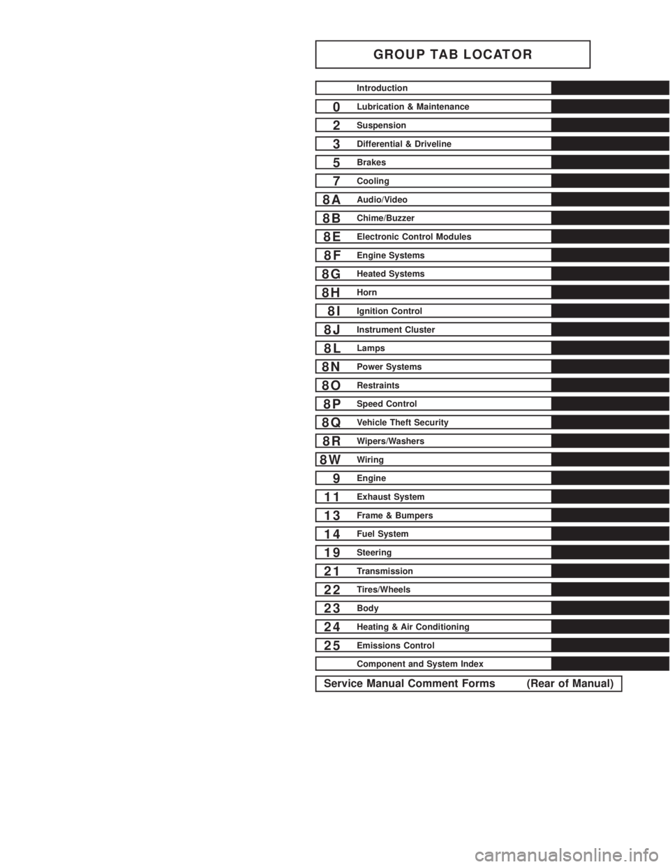
GROUP TAB LOCATOR
Introduction
0Lubrication & Maintenance
2Suspension
3Differential & Driveline
5Brakes
7Cooling
8AAudio/Video
8BChime/Buzzer
8EElectronic Control Modules
8FEngine Systems
8GHeated Systems
8HHorn
8IIgnition Control
8JInstrument Cluster
8LLamps
8NPower Systems
8ORestraints
8PSpeed Control
8QVehicle Theft Security
8RWipers/Washers
8WWiring
9Engine
11Exhaust System
13Frame & Bumpers
14Fuel System
19Steering
21Transmission
22Tires/Wheels
23Body
24Heating & Air Conditioning
25Emissions Control
Component and System Index
Service Manual Comment Forms (Rear of Manual)