2006 MERCEDES-BENZ SPRINTER steering wheel
[x] Cancel search: steering wheelPage 921 of 2305
INSTRUMENT CLUSTER
DESCRIPTION
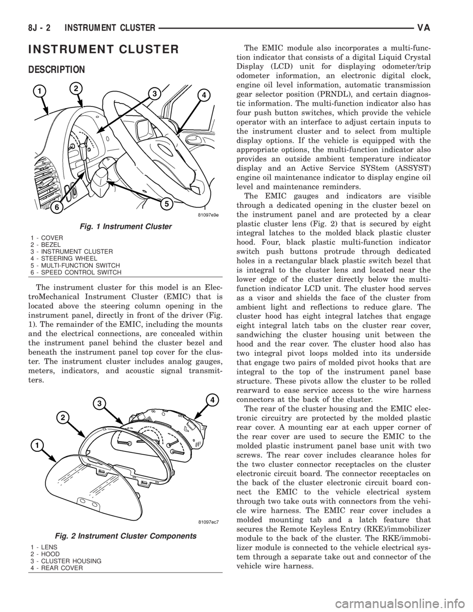
The instrument cluster for this model is an Elec-
troMechanical Instrument Cluster (EMIC) that is
located above the steering column opening in the
instrument panel, directly in front of the driver (Fig.
1). The remainder of the EMIC, including the mounts
and the electrical connections, are concealed within
the instrument panel behind the cluster bezel and
beneath the instrument panel top cover for the clus-
ter. The instrument cluster includes analog gauges,
meters, indicators, and acoustic signal transmit-
ters.The EMIC module also incorporates a multi-func-
tion indicator that consists of a digital Liquid Crystal
Display (LCD) unit for displaying odometer/trip
odometer information, an electronic digital clock,
engine oil level information, automatic transmission
gear selector position (PRNDL), and certain diagnos-
tic information. The multi-function indicator also has
four push button switches, which provide the vehicle
operator with an interface to adjust certain inputs to
the instrument cluster and to select from multiple
display options. If the vehicle is equipped with the
appropriate options, the multi-function indicator also
provides an outside ambient temperature indicator
display and an Active Service SYStem (ASSYST)
engine oil maintenance indicator to display engine oil
level and maintenance reminders.
The EMIC gauges and indicators are visible
through a dedicated opening in the cluster bezel on
the instrument panel and are protected by a clear
plastic cluster lens (Fig. 2) that is secured by eight
integral latches to the molded black plastic cluster
hood. Four, black plastic multi-function indicator
switch push buttons protrude through dedicated
holes in a rectangular black plastic switch bezel that
is integral to the cluster lens and located near the
lower edge of the cluster directly below the multi-
function indicator LCD unit. The cluster hood serves
as a visor and shields the face of the cluster from
ambient light and reflections to reduce glare. The
cluster hood has eight integral latches that engage
eight integral latch tabs on the cluster rear cover,
sandwiching the cluster housing unit between the
hood and the rear cover. The cluster hood also has
two integral pivot loops molded into its underside
that engage two pairs of molded pivot hooks that are
integral to the top of the instrument panel base
structure. These pivots allow the cluster to be rolled
rearward to ease service access to the wire harness
connectors at the back of the cluster.
The rear of the cluster housing and the EMIC elec-
tronic circuitry are protected by the molded plastic
rear cover. A mounting ear at each upper corner of
the rear cover are used to secure the EMIC to the
molded plastic instrument panel base unit with two
screws. The rear cover includes clearance holes for
the two cluster connector receptacles on the cluster
electronic circuit board. The connector receptacles on
the back of the cluster electronic circuit board con-
nect the EMIC to the vehicle electrical system
through two take outs with connectors from the vehi-
cle wire harness. The EMIC rear cover includes a
molded mounting tab and a latch feature that
secures the Remote Keyless Entry (RKE)/immobilizer
module to the back of the cluster. The RKE/immobi-
lizer module is connected to the vehicle electrical sys-
tem through a separate take out and connector of the
vehicle wire harness.
Fig. 1 Instrument Cluster
1 - COVER
2 - BEZEL
3 - INSTRUMENT CLUSTER
4 - STEERING WHEEL
5 - MULTI-FUNCTION SWITCH
6 - SPEED CONTROL SWITCH
Fig. 2 Instrument Cluster Components
1 - LENS
2 - HOOD
3 - CLUSTER HOUSING
4 - REAR COVER
8J - 2 INSTRUMENT CLUSTERVA
Page 926 of 2305

GROUNDS
The EMIC receives and supplies a ground path to
several switches and sensors through the following
hard wired circuits:
²Ambient Temperature Sensor Return
(Optional)
²Fuel Level Sensor Return
²Ground
Refer to the appropriate wiring information for
additional details.
COMMUNICATION
The EMIC has provisions for the following commu-
nication circuits:
²CAN Data Bus - High
²CAN Data Bus - Low
²Diagnostic Serial Communication Interface
(SCI) Data Bus Line
Refer to the appropriate wiring information for
additional details.
DIAGNOSIS AND TESTING - INSTRUMENT
CLUSTER
The hard wired inputs to and outputs from the
instrument cluster may be diagnosed and tested
using conventional diagnostic tools and procedures.
Refer to the appropriate wiring information. The wir-
ing information includes wiring diagrams, proper
wire and connector repair procedures, details of wire
harness routing and retention, connector pin-out
information and location views for the various wire
harness connectors, splices and grounds.
If the instrument cluster is completely inoperative,
be certain to check the fused B(+) circuit fuses and
wiring for the instrument cluster. If the cluster gen-
eral illumination is inoperative, be certain to check
the instrument lighting fuse and the input circuit to
the instrument cluster from the exterior lighting cir-
cuitry of the multi-function switch on the steering
column.
Conventional diagnostic methods may not prove
conclusive in the diagnosis of the instrument cluster.
In order to obtain conclusive testing of the instru-
ment cluster, the Controller Area Network (CAN)
data bus network and all of the electronic modules
that provide inputs to or receive outputs from the
instrument cluster must also be checked. The most
reliable, efficient, and accurate means to diagnose
the instrument cluster, the CAN data bus network,
and the electronic modules that provide inputs to or
receive outputs from the instrument cluster requires
the use of a diagnostic scan tool and the appropriate
diagnostic information. The diagnostic scan tool can
provide confirmation that the CAN data bus network
is functional, that all of the modules are sending and
receiving the proper electronic messages over the
CAN data bus, and that the instrument cluster isreceiving the proper hard wired inputs and respond-
ing with the proper hard wired outputs needed to
perform its many functions.
WARNING: To avoid personal injury or death, on
vehicles equipped with airbags, disable the supple-
mental restraint system before attempting any
steering wheel, steering column, airbag, seat belt
tensioner, or instrument panel component diagno-
sis or service. Disconnect and isolate the battery
negative (ground) cable, then wait two minutes for
the system capacitor to discharge before perform-
ing further diagnosis or service. This is the only
sure way to disable the supplemental restraint sys-
tem. Failure to take the proper precautions could
result in accidental airbag deployment.
STANDARD PROCEDURE
CLUSTER PROGRAMMING
NOTE: After replacing the Instrument Cluster (IC)
according to the service procedures, determine the
optional equipment on the vehicle by accessing the
sales code information using the Vehicle Identifica-
tion Number (VIN) on DealerCONNECT.
(1) Using the DRBIIIt, selectMISCELLANEOUS
FUNCTIONSin the Instrument Cluster (IC) section.
(2) SelectMODULE SERVICE REPLACE-
MENT.
(3) Following the prompts on the DRBIIIt, enter
the correct parameters that are applicable to the
vehicle. Use the sales code information and visual
inspection to obtain the correct parameters.
CAUTION: Do not lock down the instrument cluster
until the following steps are followed or the instru-
ment cluster may be irreversibly damaged.
(4) After entering the proper parameters into the
IC, turn the ignition switch to the OFF position for
30 seconds, then turn the ignition switch ON.
(5) Test drive the vehicle for at least 10 minutes
before proceeding.
(6) Check ALL modules for any parameterization
DTCs. If any parameterization DTCs are present, one
or more parameters entered into the IC are incorrect.
Verify all parameters entered using the sales code
information and visual inspection of the vehicle.
(7) If the parameters entered are verified as cor-
rect and parameterization DTCs are still present,
refer to the appropriate diagnostic information.
(8) If no parameterization DTCs are present, lock
down the IC.
VAINSTRUMENT CLUSTER 8J - 7
Page 927 of 2305
NOTE: Mileage will not be displayed until the IC has
been locked down.
REMOVAL
WARNING: To avoid personal injury or death, on
vehicles equipped with airbags, disable the supple-
mental restraint system before attempting any
steering wheel, steering column, airbag, seat belt
tensioner, or instrument panel component diagno-
sis or service. Disconnect and isolate the battery
negative (ground) cable, then wait two minutes for
the system capacitor to discharge before perform-
ing further diagnosis or service. This is the only
sure way to disable the supplemental restraint sys-
tem. Failure to take the proper precautions could
result in accidental airbag deployment.
CAUTION: The following procedure is for replace-
ment of an ineffective and unresponsive Instrument
Cluster (IC) with a new unit. If the IC is ineffective
or damaged but still responsive, it may be replaced
using an automatic replacement procedure that will
upload IC parameterization data from the existing IC
to the diagnostic scan tool, then download that data
to the new IC. Refer to the MISCELLANEOUS FUNC-
TIONS menu item under the IC module in the diag-
nostic scan tool, then select MODULE AUTO
REPLACEMENT and follow the scan tool prompts to
replace the IC. Do not lock down the IC until all of
the steps are followed and completed or the new IC
may be irreversibly damaged. This procedure initial-
izes and configures the IC for certain optional
equipment on the vehicle without the need for per-
forming a separate cluster programming procedure.
Failure to correctly parameterize the IC prior to it
being electronically locked down will result in the
IC being incorrectly and irreversibly configured for
improper vehicle equipment options, which will
require the IC be replaced again with another new
and unused unit to resolve.
(1) Disconnect and isolate the battery negative
cable.
(2) Remove the cluster bezel from the instrument
panel. (Refer to 23 - BODY/INSTRUMENT PANEL/
CLUSTER BEZEL - REMOVAL).
(3) Remove the cluster top cover from the instru-
ment panel. (Refer to 23 - BODY/INSTRUMENT
PANEL/TOP COVER - CLUSTER - REMOVAL).
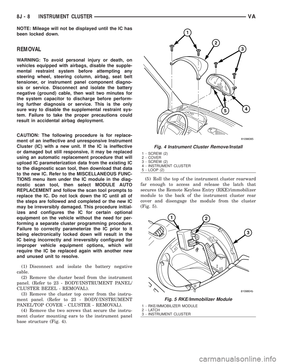
(4) Remove the two screws that secure the instru-
ment cluster mounting ears to the instrument panel
base structure (Fig. 4).(5) Roll the top of the instrument cluster rearward
far enough to access and release the latch that
secures the Remote Keyless Entry (RKE)/immobilizer
module to the back of the instrument cluster rear
cover and disengage the module from the cluster
(Fig. 5).
Fig. 4 Instrument Cluster Remove/Install
1 - SCREW (2)
2 - COVER
3 - SCREW (2)
4 - INSTRUMENT CLUSTER
5 - LOOP (2)
Fig. 5 RKE/Immobilizer Module
1 - RKE/IMMOBILIZER MODULE
2-LATCH
3 - INSTRUMENT CLUSTER
8J - 8 INSTRUMENT CLUSTERVA
Page 928 of 2305
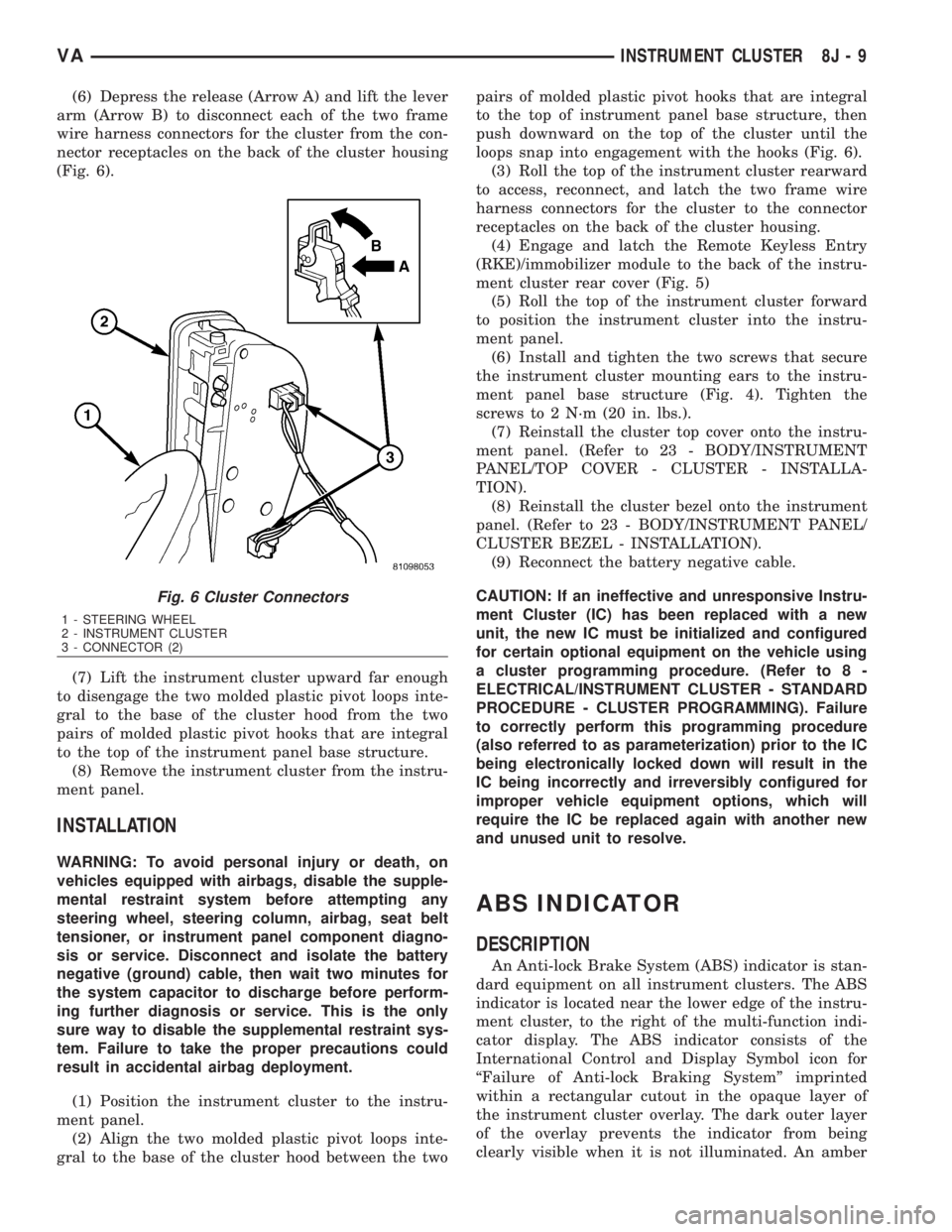
(6) Depress the release (Arrow A) and lift the lever
arm (Arrow B) to disconnect each of the two frame
wire harness connectors for the cluster from the con-
nector receptacles on the back of the cluster housing
(Fig. 6).
(7) Lift the instrument cluster upward far enough
to disengage the two molded plastic pivot loops inte-
gral to the base of the cluster hood from the two
pairs of molded plastic pivot hooks that are integral
to the top of the instrument panel base structure.
(8) Remove the instrument cluster from the instru-
ment panel.
INSTALLATION
WARNING: To avoid personal injury or death, on
vehicles equipped with airbags, disable the supple-
mental restraint system before attempting any
steering wheel, steering column, airbag, seat belt
tensioner, or instrument panel component diagno-
sis or service. Disconnect and isolate the battery
negative (ground) cable, then wait two minutes for
the system capacitor to discharge before perform-
ing further diagnosis or service. This is the only
sure way to disable the supplemental restraint sys-
tem. Failure to take the proper precautions could
result in accidental airbag deployment.
(1) Position the instrument cluster to the instru-
ment panel.
(2) Align the two molded plastic pivot loops inte-
gral to the base of the cluster hood between the twopairs of molded plastic pivot hooks that are integral
to the top of instrument panel base structure, then
push downward on the top of the cluster until the
loops snap into engagement with the hooks (Fig. 6).
(3) Roll the top of the instrument cluster rearward
to access, reconnect, and latch the two frame wire
harness connectors for the cluster to the connector
receptacles on the back of the cluster housing.
(4) Engage and latch the Remote Keyless Entry
(RKE)/immobilizer module to the back of the instru-
ment cluster rear cover (Fig. 5)
(5) Roll the top of the instrument cluster forward
to position the instrument cluster into the instru-
ment panel.
(6) Install and tighten the two screws that secure
the instrument cluster mounting ears to the instru-
ment panel base structure (Fig. 4). Tighten the
screws to 2 N´m (20 in. lbs.).
(7) Reinstall the cluster top cover onto the instru-
ment panel. (Refer to 23 - BODY/INSTRUMENT
PANEL/TOP COVER - CLUSTER - INSTALLA-
TION).
(8) Reinstall the cluster bezel onto the instrument
panel. (Refer to 23 - BODY/INSTRUMENT PANEL/
CLUSTER BEZEL - INSTALLATION).
(9) Reconnect the battery negative cable.
CAUTION: If an ineffective and unresponsive Instru-
ment Cluster (IC) has been replaced with a new
unit, the new IC must be initialized and configured
for certain optional equipment on the vehicle using
a cluster programming procedure. (Refer to 8 -
ELECTRICAL/INSTRUMENT CLUSTER - STANDARD
PROCEDURE - CLUSTER PROGRAMMING). Failure
to correctly perform this programming procedure
(also referred to as parameterization) prior to the IC
being electronically locked down will result in the
IC being incorrectly and irreversibly configured for
improper vehicle equipment options, which will
require the IC be replaced again with another new
and unused unit to resolve.
ABS INDICATOR
DESCRIPTION
An Anti-lock Brake System (ABS) indicator is stan-
dard equipment on all instrument clusters. The ABS
indicator is located near the lower edge of the instru-
ment cluster, to the right of the multi-function indi-
cator display. The ABS indicator consists of the
International Control and Display Symbol icon for
ªFailure of Anti-lock Braking Systemº imprinted
within a rectangular cutout in the opaque layer of
the instrument cluster overlay. The dark outer layer
of the overlay prevents the indicator from being
clearly visible when it is not illuminated. An amber
Fig. 6 Cluster Connectors
1 - STEERING WHEEL
2 - INSTRUMENT CLUSTER
3 - CONNECTOR (2)
VAINSTRUMENT CLUSTER 8J - 9
Page 951 of 2305
REAR TURN LAMP BULB
REMOVAL.............................23
INSTALLATION.........................23
REPEATER LAMP BULB
REMOVAL.............................23
INSTALLATION.........................24
REPEATER LAMP UNIT
REMOVAL.............................24INSTALLATION.........................25
TAIL LAMP UNIT
REMOVAL.............................25
INSTALLATION.........................26
TURN SIGNAL RELAY
REMOVAL.............................26
INSTALLATION.........................26
LAMPS / LIGHTING - EXTE-
RIOR
DESCRIPTION
The exterior lighting system for this model
includes the following exterior lamps:
²Backup Lamps- The backup (or reverse) lamps
are integral to the tail lamp units mounted to the
back of the quarter panel on each side of the tailgate
at the rear of the vehicle.
²Brake Lamps- The brake (or stop) lamps
include a bulb and reflector that are integral to the
tail lamp units mounted to the back of the quarter
panel on each side of the tailgate opening, and the
Center High Mounted Stop Lamp (CHMSL) that is
centered on the rear edge of the roof panel above the
tailgate opening.
²Daytime Running Lamps- Vehicles manufac-
tured for sale in Canada have a Daytime Running
Lamps (DRL) relay that illuminates the low beam
headlamp bulbs whenever the engine is running.
²Fog Lamps- Fog lamp bulbs and reflectors are
included in both front lamp units of vehicles
equipped with this option.
²Hazard Warning Lamps- The hazard warning
lamps include all of the right and left turn signal and
repeater lamps.
²Headlamps- Separate low beam and high
beam headlamp bulbs are installed in the front lamp
unit on each side of the front grille opening. A head-
lamp leveling actuator motor is also integral to each
front lamp unit.
²Park Lamps- The park lamps include the front
park/side marker lamps and front position lamps
that are integral to the front lamp units mounted on
either side of the front grille opening, as well as the
rear park lamps and rear side marker lamps that are
integral to the tail lamp units mounted to the back of
the quarter panel on each side of the tailgate open-
ing. Included in the park lamps circuit are two rear
license plate lamp units mounted on the left rear
tailgate door. The park lamps may also include
optional clearance lamps, which are located on each
side of a vehicle that is so equipped.
²Turn Signal Lamps- The turn signal lamps
include the front turn lamps that are integral to the
front lamp units, the rear turn lamps that are inte-
gral to the tail lamp units, and a repeater lampmounted to each front fender just above the front
wheel opening.
Other components of the exterior lighting system
for this model include:
²Brake Lamp Switch- A plunger-type brake
lamp switch is located on the steering column sup-
port bracket under the instrument panel and actu-
ated by the brake pedal arm.
²Daytime Running Lamp Relays- Vehicles
manufactured for sale in Canada have two Daytime
Running Lamps (DRL) relays. Dedicated right and
left side relays illuminate the low beam headlamp
bulb installed in each front lamp unit whenever the
engine is running. These relays are located in dedi-
cated vehicle wire harness connectors within the
driver side front seat riser.
²Fog Lamp Relay- Vehicles equipped with the
optional fog lamps have a fog lamp relay located in a
dedicated vehicle wire harness connector within the
driver side front seat riser.
²Fog Lamp Switch- A fog lamp switch is
mounted in the instrument cluster bezel, below the
cluster and outboard of the steering column on vehi-
cles equipped with this option.
²Headlamp Leveling Motor- A headlamp lev-
eling actuator motor is located on the back of each
headlamp housing and adjusts both the low beam
headlamp, high beam headlamp, and fog lamp (if
equipped) reflector frames in unison.
²Headlamp Leveling Switch- A thumbwheel
actuated headlamp leveling switch is mounted in the
instrument cluster bezel, below the cluster and out-
board of the steering column.
²Multi-Function Switch- The multi-function
switch is located on the top of the steering column,
just below the steering wheel. The multi-function
switch is connected directly to the fuse block located
below the steering column through an integral inter-
face connector. Only the left (lighting), right (wiper)
control stalks and the hazard warning switch button
for the multi-function switch are visible, the remain-
der of the switch is concealed beneath the steering
column shrouds. The multi-function switch includes a
left (lighting) control stalk and a right (wiper) control
stalk. The left control stalk is dedicated to providing
almost all of the driver controls for the exterior light-
ing system.
²Trailer Tow Connector- Vehicles equipped
with a factory-approved, field-installed trailer towing
8L - 2 LAMPS/LIGHTING - EXTERIORVA
Page 953 of 2305
seat riser, a fog lamp switch installed in the cluster
bezel on the instrument panel outboard of the steer-
ing column, and a fog lamp bulb installed in each of
the two front lamp units. The front fog lamps have a
path to ground at all times through their connection
to the vehicle wire harness. The headlamp switch cir-
cuitry of the left (lighting) control stalk of the multi-
function switch controls front fog lamp operation by
providing battery current to the front fog lamp relay
only when the low beam headlamps are selected. The
fog lamp switch controls front fog lamp operation by
energizing or de-energizing the front fog lamp relay
control coil.
HAZARD WARNING LAMPS
With the hazard switch in the On position, the
hazard switch button illuminates and the right and
left turn signal indicators as well as the right and
left turn signal lamps begin to flash on and off. When
the hazard warning system is activated, the hazard
switch circuitry within the multi-function switch and
the wipers, turn signals and engine start control
module electronic circuitry within the fuse block will
repeatedly energize and de-energize the turn signal
relay located in the fuse block. The turn signal relay
switches battery current from a fused B(+) fuse in
the fuse block to the turn signal indicators and the
turn signal lamps. The flashing of the hazard switch
button illumination lamp is also controlled by the
output from the turn signal relay.
HEADLAMPS
The headlamp system includes the exterior lighting
switches integral to the left (lighting) control stalk of
the multi-function switch as well as the low and high
beam bulbs installed in the right and left front lamp
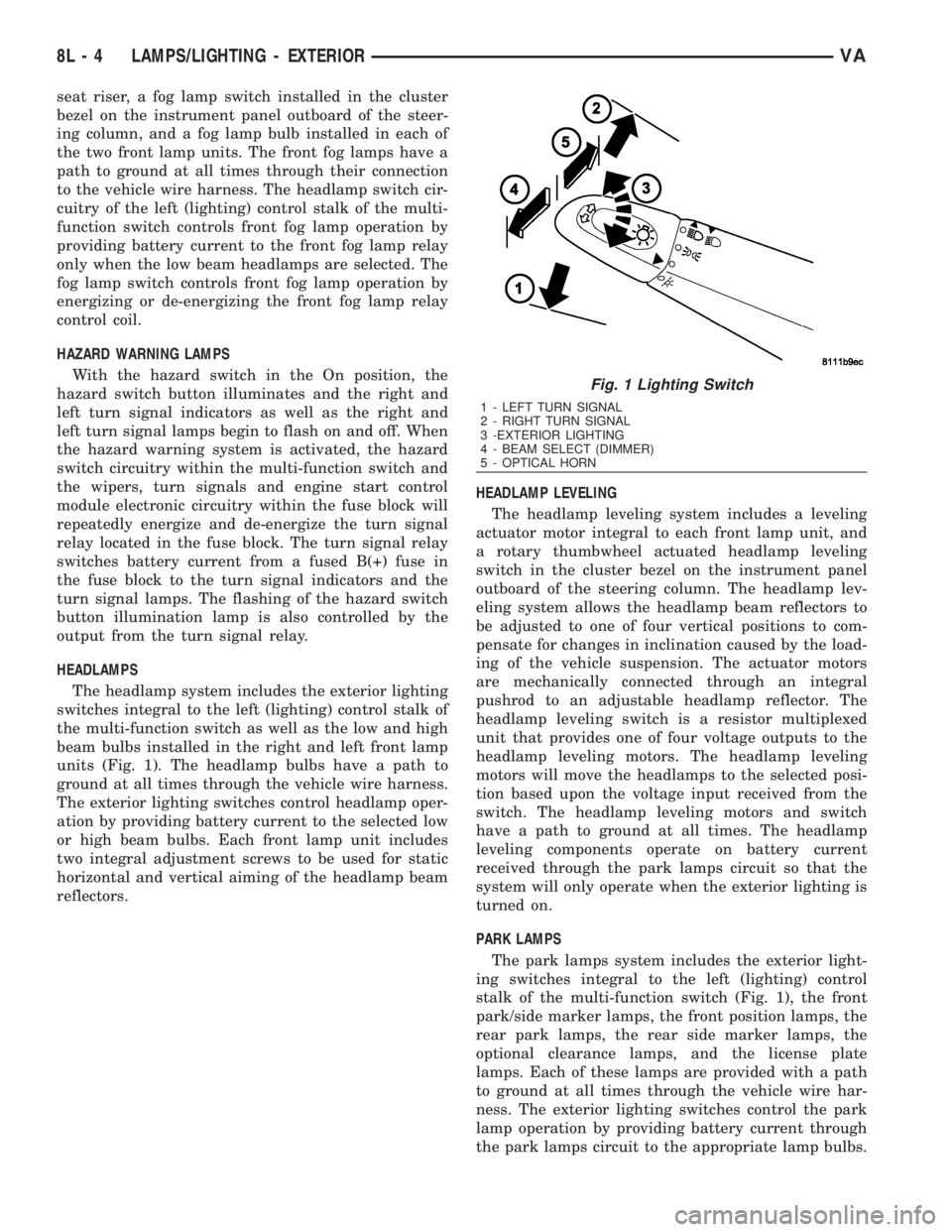
units (Fig. 1). The headlamp bulbs have a path to
ground at all times through the vehicle wire harness.
The exterior lighting switches control headlamp oper-
ation by providing battery current to the selected low
or high beam bulbs. Each front lamp unit includes
two integral adjustment screws to be used for static
horizontal and vertical aiming of the headlamp beam
reflectors.HEADLAMP LEVELING
The headlamp leveling system includes a leveling
actuator motor integral to each front lamp unit, and
a rotary thumbwheel actuated headlamp leveling
switch in the cluster bezel on the instrument panel
outboard of the steering column. The headlamp lev-
eling system allows the headlamp beam reflectors to
be adjusted to one of four vertical positions to com-
pensate for changes in inclination caused by the load-
ing of the vehicle suspension. The actuator motors
are mechanically connected through an integral
pushrod to an adjustable headlamp reflector. The
headlamp leveling switch is a resistor multiplexed
unit that provides one of four voltage outputs to the
headlamp leveling motors. The headlamp leveling
motors will move the headlamps to the selected posi-
tion based upon the voltage input received from the
switch. The headlamp leveling motors and switch
have a path to ground at all times. The headlamp
leveling components operate on battery current
received through the park lamps circuit so that the
system will only operate when the exterior lighting is
turned on.
PARK LAMPS
The park lamps system includes the exterior light-
ing switches integral to the left (lighting) control
stalk of the multi-function switch (Fig. 1), the front
park/side marker lamps, the front position lamps, the
rear park lamps, the rear side marker lamps, the
optional clearance lamps, and the license plate
lamps. Each of these lamps are provided with a path
to ground at all times through the vehicle wire har-
ness. The exterior lighting switches control the park
lamp operation by providing battery current through
the park lamps circuit to the appropriate lamp bulbs.
Fig. 1 Lighting Switch
1 - LEFT TURN SIGNAL
2 - RIGHT TURN SIGNAL
3 -EXTERIOR LIGHTING
4 - BEAM SELECT (DIMMER)
5 - OPTICAL HORN
8L - 4 LAMPS/LIGHTING - EXTERIORVA
Page 955 of 2305
(5) Remove the backup lamp bulb from the tail
lamp socket plate.
INSTALLATION
(1) Install the backup lamp bulb into the tail lamp
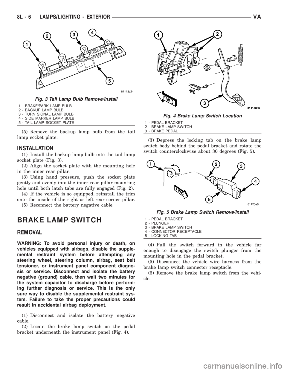
socket plate (Fig. 3).
(2) Align the socket plate with the mounting hole
in the inner rear pillar.
(3) Using hand pressure, push the socket plate
gently and evenly into the inner rear pillar mounting
hole until both latch tabs are fully engaged (Fig. 2).
(4) If the vehicle is so equipped, reinstall the trim
onto the inside of the right or left rear corner pillar.
(5) Reconnect the battery negative cable.
BRAKE LAMP SWITCH
REMOVAL
WARNING: To avoid personal injury or death, on
vehicles equipped with airbags, disable the supple-
mental restraint system before attempting any
steering wheel, steering column, airbag, seat belt
tensioner, or instrument panel component diagno-
sis or service. Disconnect and isolate the battery
negative (ground) cable, then wait two minutes for
the system capacitor to discharge before perform-
ing further diagnosis or service. This is the only
sure way to disable the supplemental restraint sys-
tem. Failure to take the proper precautions could
result in accidental airbag deployment.
(1) Disconnect and isolate the battery negative
cable.
(2) Locate the brake lamp switch on the pedal
bracket underneath the instrument panel (Fig. 4).(3) Depress the locking tab on the brake lamp
switch body behind the pedal bracket and rotate the
switch counterclockwise about 30 degrees (Fig. 5).
(4) Pull the switch forward in the vehicle far
enough to disengage the switch plunger from the
mounting hole in the pedal bracket.
(5) Disconnect the vehicle wire harness from the
brake lamp switch connector receptacle.
(6) Remove the brake lamp switch from the vehi-
cle.
Fig. 3 Tail Lamp Bulb Remove/Install
1 - BRAKE/PARK LAMP BULB
2 - BACKUP LAMP BULB
3 - TURN SIGNAL LAMP BULB
4 - SIDE MARKER LAMP BULB
5 - TAIL LAMP SOCKET PLATE
Fig. 4 Brake Lamp Switch Location
1 - PEDAL BRACKET
2 - BRAKE LAMP SWITCH
3 - BRAKE PEDAL
Fig. 5 Brake Lamp Switch Remove/Install
1 - PEDAL BRACKET
2 - PLUNGER
3 - BRAKE LAMP SWITCH
4 - CONNECTOR RECEPTACLE
5 - LOCKING TAB
8L - 6 LAMPS/LIGHTING - EXTERIORVA
Page 956 of 2305
INSTALLATION
WARNING: To avoid personal injury or death, on
vehicles equipped with airbags, disable the supple-
mental restraint system before attempting any
steering wheel, steering column, airbag, seat belt
tensioner, or instrument panel component diagno-
sis or service. Disconnect and isolate the battery
negative (ground) cable, then wait two minutes for
the system capacitor to discharge before perform-
ing further diagnosis or service. This is the only
sure way to disable the supplemental restraint sys-
tem. Failure to take the proper precautions could
result in accidental airbag deployment.
(1) Pull the plunger of the brake lamp switch out-
ward from the switch body to its travel limit (Fig. 5).
(2) Reconnect the vehicle wire harness to the
brake lamp switch connector receptacle.
(3) Depress and hold the brake pedal in the
depressed position until the brake lamp switch
installation is completed (Fig. 4).
(4) Insert the brake lamp switch plunger through
the mounting hole from behind until the switch lock-
ing collar is fully seated against the pedal bracket.
(5) Rotate the brake lamp switch clockwise until
the locking tab on the switch body fully engages the
pedal bracket. Full locking tab engagement will be
accompanied by an audible click.
NOTE: Do not pull the brake pedal upwards as this
will adjust the switch plunger to an incorrect posi-
tion. The switch is properly adjusted when the
switch plunger is just contacting (no gap) the brake
pedal arm with the pedal in the relaxed (released)
position.
(6) Release the brake pedal from its depressed
position to automatically adjust the brake lamp
switch plunger.
(7) Reconnect the battery negative cable.
ADJUSTMENTS
ADJUSTMENT
WARNING: To avoid personal injury or death, on
vehicles equipped with airbags, disable the supple-
mental restraint system before attempting any
steering wheel, steering column, airbag, seat belt
tensioner, or instrument panel component diagno-
sis or service. Disconnect and isolate the battery
negative (ground) cable, then wait two minutes for
the system capacitor to discharge before perform-
ing further diagnosis or service. This is the only
sure way to disable the supplemental restraint sys-tem. Failure to take the proper precautions could
result in accidental airbag deployment.
(1) Disconnect and isolate the battery negative
cable.
(2) Depress and hold the brake pedal in the
depressed position until the brake lamp switch
adjustment is completed.
(3) Pull the plunger of the brake lamp switch out-
ward from the switch body to its travel limit.
NOTE: Do not pull the brake pedal upwards as this
will adjust the switch plunger to an incorrect posi-
tion. The switch is properly adjusted when the
switch plunger is just contacting (no gap) the brake
pedal arm with the pedal in the relaxed (released)
position.
(4) Release the brake pedal from its depressed
position to automatically adjust the brake lamp
switch plunger.
BRAKE / PARK LAMP BULB
REMOVAL
(1) Disconnect and isolate the battery negative
cable.
(2) If the vehicle is so equipped, remove the trim
from the inside of the right or left rear corner pillar.
(3) From inside the vehicle, use hand pressure to
push the two latch tabs toward the center of the tail
lamp unit socket plate and pull the socket plate
straight out from the inner rear pillar (Fig. 6).
VALAMPS/LIGHTING - EXTERIOR 8L - 7