2006 MERCEDES-BENZ SPRINTER air condition
[x] Cancel search: air conditionPage 1732 of 2305
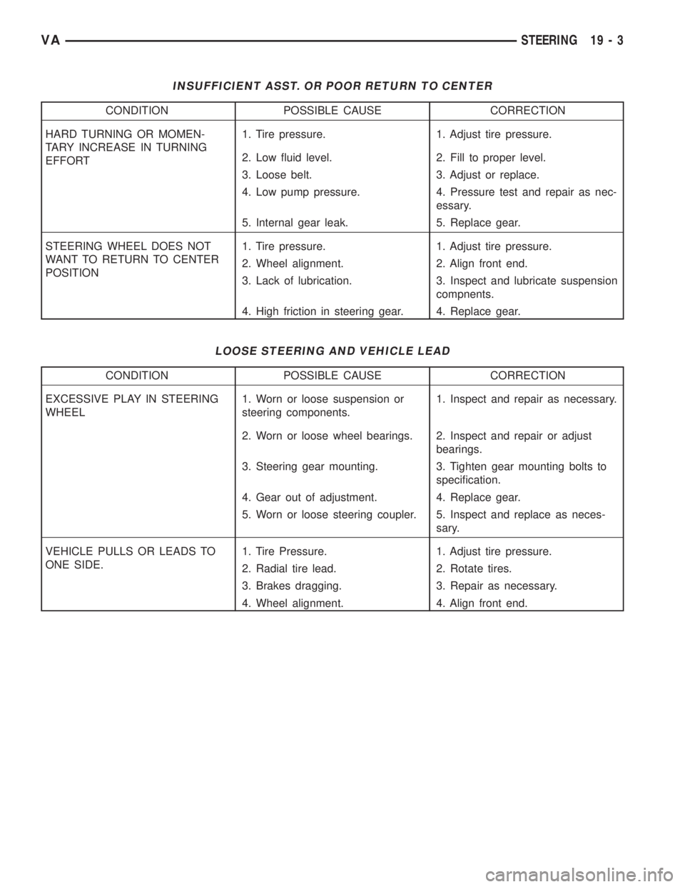
INSUFFICIENT ASST. OR POOR RETURN TO CENTER
CONDITION POSSIBLE CAUSE CORRECTION
HARD TURNING OR MOMEN-
TARY INCREASE IN TURNING
EFFORT1. Tire pressure. 1. Adjust tire pressure.
2. Low fluid level. 2. Fill to proper level.
3. Loose belt. 3. Adjust or replace.
4. Low pump pressure. 4. Pressure test and repair as nec-
essary.
5. Internal gear leak. 5. Replace gear.
STEERING WHEEL DOES NOT
WANT TO RETURN TO CENTER
POSITION1. Tire pressure. 1. Adjust tire pressure.
2. Wheel alignment. 2. Align front end.
3. Lack of lubrication. 3. Inspect and lubricate suspension
compnents.
4. High friction in steering gear. 4. Replace gear.
LOOSE STEERING AND VEHICLE LEAD
CONDITION POSSIBLE CAUSE CORRECTION
EXCESSIVE PLAY IN STEERING
WHEEL1. Worn or loose suspension or
steering components.1. Inspect and repair as necessary.
2. Worn or loose wheel bearings. 2. Inspect and repair or adjust
bearings.
3. Steering gear mounting. 3. Tighten gear mounting bolts to
specification.
4. Gear out of adjustment. 4. Replace gear.
5. Worn or loose steering coupler. 5. Inspect and replace as neces-
sary.
VEHICLE PULLS OR LEADS TO
ONE SIDE.1. Tire Pressure. 1. Adjust tire pressure.
2. Radial tire lead. 2. Rotate tires.
3. Brakes dragging. 3. Repair as necessary.
4. Wheel alignment. 4. Align front end.
VASTEERING 19 - 3
Page 1782 of 2305
DIAGNOSIS AND TESTING
AUTOMATIC TRANSMISSION
CAUTION: Before attempting any repair on a NAG1
automatic transmission, check for Diagnostic Trou-
ble Codes with the appropriate scan tool.
Transmission malfunctions may be caused by these
general conditions:
²Poor engine performance.
²Improper adjustments.
²Hydraulic malfunctions.
²Mechanical malfunctions.
²Electronic malfunctions.
²Transfer case performance (if equipped).
Diagnosis of these problems should always begin
by checking the easily accessible variables: fluid level
and condition, gearshift cable adjustment. Then per-
form a road test to determine if the problem has been
corrected or if more diagnosis is necessary.
PRELIMINARY
Two basic procedures are required. One procedure
for vehicles that are drivable and an alternate proce-
dure for disabled vehicles (will not back up or move
forward).
VEHICLE IS DRIVABLE
(1) Check for transmission fault codes using the
appropriate scan tool.
(2) Check fluid level and condition.
(3) Adjust gearshift cable if complaint was based
on delayed, erratic, or harsh shifts.
(4) Road test and note how transmission upshifts,
downshifts, and engages.
VEHICLE IS DISABLED
(1) Check fluid level and condition.(2) Check for broken or disconnected gearshift
cable.
(3) Check for cracked, leaking cooler lines, or loose
or missing pressure-port plugs.
(4) Raise and support vehicle on safety stands,
start engine, shift transmission into gear, and note
following:
(a) If propeller shaft turns but wheels do not,
problem is with differential or axle shafts.
(b) If propeller shaft does not turn and transmis-
sion is noisy, stop engine. Remove oil pan, and
check for debris. If pan is clear, remove transmis-
sion and check for damaged driveplate, converter,
oil pump, or input shaft.
(c) If propeller shaft does not turn and transmis-
sion is not noisy, perform hydraulic-pressure test to
determine if problem is hydraulic or mechanical.
ROAD TESTING
Before road testing, be sure the fluid level and con-
trol cable adjustments have been checked and
adjusted if necessary. Verify that all diagnostic trou-
ble codes have been resolved.
Observe engine performance during the road test.
A poorly tuned engine will not allow accurate analy-
sis of transmission operation.
Operate the transmission in all gear ranges. Check
for shift variations and engine flare which indicates
slippage. Note if shifts are harsh, spongy, delayed,
early, or if part throttle downshifts are sensitive.
Slippage indicated by engine flare, usually means
clutch, overrunning clutch, or line pressure problems.
A slipping clutch can often be determined by com-
paring which internal units are applied in the vari-
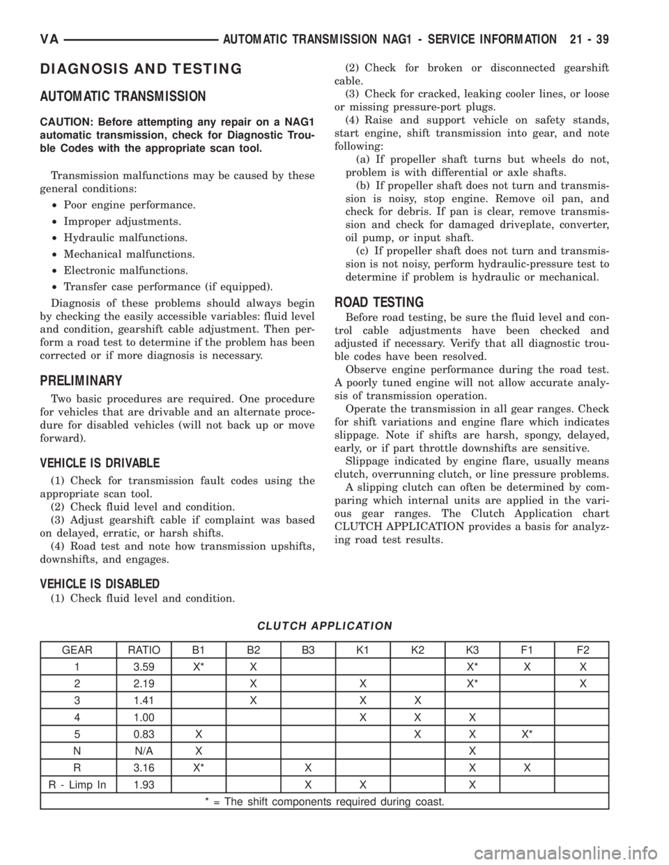
ous gear ranges. The Clutch Application chart
CLUTCH APPLICATION provides a basis for analyz-
ing road test results.
CLUTCH APPLICATION
GEAR RATIO B1 B2 B3 K1 K2 K3 F1 F2
1 3.59 X* X X* X X
2 2.19 X X X* X
3 1.41 X X X
4 1.00 X X X
5 0.83 X X X X*
N N/A X X
R 3.16 X* X X X
R - Limp In 1.93 X X X
* = The shift components required during coast.
VAAUTOMATIC TRANSMISSION NAG1 - SERVICE INFORMATION 21 - 39
Page 1784 of 2305
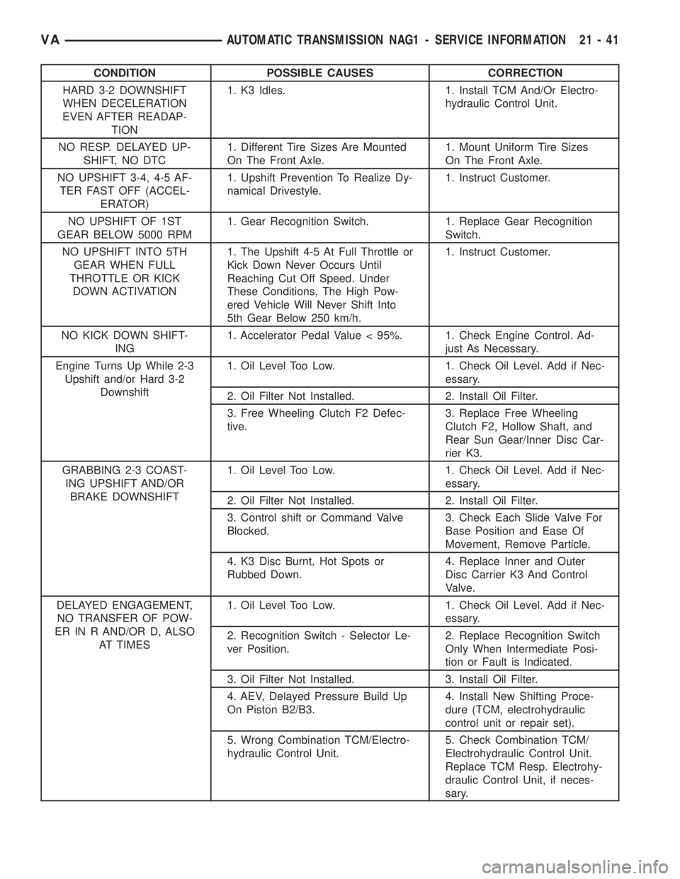
CONDITION POSSIBLE CAUSES CORRECTION
HARD 3-2 DOWNSHIFT
WHEN DECELERATION
EVEN AFTER READAP-
TION1. K3 Idles. 1. Install TCM And/Or Electro-
hydraulic Control Unit.
NO RESP. DELAYED UP-
SHIFT, NO DTC1. Different Tire Sizes Are Mounted
On The Front Axle.1. Mount Uniform Tire Sizes
On The Front Axle.
NO UPSHIFT 3-4, 4-5 AF-
TER FAST OFF (ACCEL-
ERATOR)1. Upshift Prevention To Realize Dy-
namical Drivestyle.1. Instruct Customer.
NO UPSHIFT OF 1ST
GEAR BELOW 5000 RPM1. Gear Recognition Switch. 1. Replace Gear Recognition
Switch.
NO UPSHIFT INTO 5TH
GEAR WHEN FULL
THROTTLE OR KICK
DOWN ACTIVATION1. The Upshift 4-5 At Full Throttle or
Kick Down Never Occurs Until
Reaching Cut Off Speed. Under
These Conditions, The High Pow-
ered Vehicle Will Never Shift Into
5th Gear Below 250 km/h.1. Instruct Customer.
NO KICK DOWN SHIFT-
ING1. Accelerator Pedal Value < 95%. 1. Check Engine Control. Ad-
just As Necessary.
Engine Turns Up While 2-3
Upshift and/or Hard 3-2
Downshift1. Oil Level Too Low. 1. Check Oil Level. Add if Nec-
essary.
2. Oil Filter Not Installed. 2. Install Oil Filter.
3. Free Wheeling Clutch F2 Defec-
tive.3. Replace Free Wheeling
Clutch F2, Hollow Shaft, and
Rear Sun Gear/Inner Disc Car-
rier K3.
GRABBING 2-3 COAST-
ING UPSHIFT AND/OR
BRAKE DOWNSHIFT1. Oil Level Too Low. 1. Check Oil Level. Add if Nec-
essary.
2. Oil Filter Not Installed. 2. Install Oil Filter.
3. Control shift or Command Valve
Blocked.3. Check Each Slide Valve For
Base Position and Ease Of
Movement, Remove Particle.
4. K3 Disc Burnt, Hot Spots or
Rubbed Down.4. Replace Inner and Outer
Disc Carrier K3 And Control
Valve.
DELAYED ENGAGEMENT,
NO TRANSFER OF POW-
ER IN R AND/OR D, ALSO
AT TIMES1. Oil Level Too Low. 1. Check Oil Level. Add if Nec-
essary.
2. Recognition Switch - Selector Le-
ver Position.2. Replace Recognition Switch
Only When Intermediate Posi-
tion or Fault is Indicated.
3. Oil Filter Not Installed. 3. Install Oil Filter.
4. AEV, Delayed Pressure Build Up
On Piston B2/B3.4. Install New Shifting Proce-
dure (TCM, electrohydraulic
control unit or repair set).
5. Wrong Combination TCM/Electro-
hydraulic Control Unit.5. Check Combination TCM/
Electrohydraulic Control Unit.
Replace TCM Resp. Electrohy-
draulic Control Unit, if neces-
sary.
VAAUTOMATIC TRANSMISSION NAG1 - SERVICE INFORMATION 21 - 41
Page 1785 of 2305
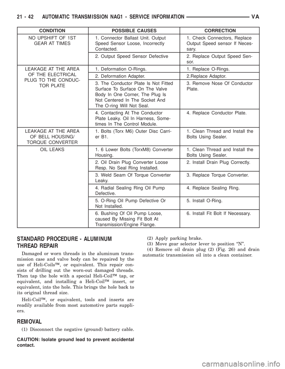
CONDITION POSSIBLE CAUSES CORRECTION
NO UPSHIFT OF 1ST
GEAR AT TIMES1. Connector Ballast Unit. Output
Speed Sensor Loose, Incorrectly
Contacted.1. Check Connectors, Replace
Output Speed sensor If Neces-
sary.
2. Output Speed Sensor Defective 2. Replace Output Speed Sen-
sor.
LEAKAGE AT THE AREA
OF THE ELECTRICAL
PLUG TO THE CONDUC-
TOR PLATE1. Deformation O-Rings. 1. Replace O-Rings.
2. Deformation Adapter. 2.Replace Adaptor.
3. The Conductor Plate Is Not Fitted
Surface To Surface On The Valve
Body In One Corner, The Plug Is
Not Centered In The Socket And
The O-ring Will Not Seal.3. Remove Nose Of Conductor
Plate.
4. Contacting At The Conductor
Plate Leaky. Oil In Harness, Some-
times In The Control Module.4. Replace Conductor Plate.
LEAKAGE AT THE AREA
OF BELL HOUSING/
TORQUE CONVERTER1. Bolts (Torx M6) Outer Disc Carri-
er B1.1. Clean Thread and Install the
Bolts Using Sealer.
OIL LEAKS 1. 6 Lower Bolts (TorxM8) Converter
Housing.1. Clean Thread and Install the
Bolts Using Sealer.
2. Oil Drain Plug Converter Loose
Resp. No Seal Ring Installed.2. Install Drain Plug Correctly.
3. Weld Seam Of Torque Converter
Leaky.3. Replace Torque Converter.
4. Radial Sealing Ring Oil Pump
Defective.4. Replace Sealing Ring.
5. O-Ring Oil Pump Defective Or
Not Installed.5. Install O-Ring.
6. Bushing Of Oil Pump Loose,
caused By Missing Fit Bolt At
Transmission/Engine Flange.6. Install Fit Bolt If Necessary.
STANDARD PROCEDURE - ALUMINUM
THREAD REPAIR
Damaged or worn threads in the aluminum trans-
mission case and valve body can be repaired by the
use of Heli-CoilsŸ, or equivalent. This repair con-
sists of drilling out the worn-out damaged threads.
Then tap the hole with a special Heli-CoilŸ tap, or
equivalent, and installing a Heli-CoilŸ insert, or
equivalent, into the hole. This brings the hole back to
its original thread size.
Heli-CoilŸ, or equivalent, tools and inserts are
readily available from most automotive parts suppli-
ers.
REMOVAL
(1) Disconnect the negative (ground) battery cable.
CAUTION: Isolate ground lead to prevent accidental
contact.(2) Apply parking brake.
(3) Move gear selector lever to position ªNº.
(4) Remove oil drain plug (2) (Fig. 26) and drain
automatic transmission oil into a clean container.
21 - 42 AUTOMATIC TRANSMISSION NAG1 - SERVICE INFORMATIONVA
Page 1874 of 2305
FLUID AND FILTER
DESCRIPTION
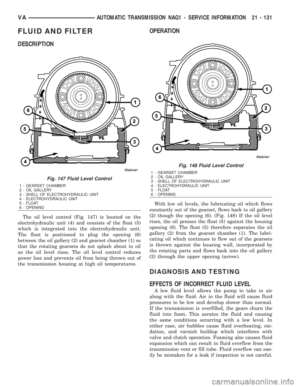
The oil level control (Fig. 147) is located on the
electrohydraulic unit (4) and consists of the float (5)
which is integrated into the electrohydraulic unit.
The float is positioned to plug the opening (6)
between the oil gallery (2) and gearset chamber (1) so
that the rotating gearsets do not splash about in oil
as the oil level rises. The oil level control reduces
power loss and prevents oil from being thrown out of
the transmission housing at high oil temperatures.
OPERATION
With low oil levels, the lubricating oil which flows
constantly out of the gearset, flows back to oil gallery
(2) though the opening (6). (Fig. 148) If the oil level
rises, the oil presses the float (5) against the housing
opening (6). The float (5) therefore separates the oil
gallery (2) from the gearset chamber (1). The lubri-
cating oil which continues to flow out of the gearsets
is thrown against the housing wall, incorporated by
the rotating parts and flows back into the oil gallery
(2) through the upper opening (arrow).
DIAGNOSIS AND TESTING
EFFECTS OF INCORRECT FLUID LEVEL
A low fluid level allows the pump to take in air
along with the fluid. Air in the fluid will cause fluid
pressures to be low and develop slower than normal.
If the transmission is overfilled, the gears churn the
fluid into foam. This aerates the fluid and causing
the same conditions occurring with a low level. In
either case, air bubbles cause fluid overheating, oxi-
dation, and varnish buildup which interferes with
valve and clutch operation. Foaming also causes fluid
expansion which can result in fluid overflow from the
transmission vent or fill tube. Fluid overflow can eas-
ily be mistaken for a leak if inspection is not careful.
Fig. 147 Fluid Level Control
1 - GEARSET CHAMBER
2 - OIL GALLERY
3 - SHELL OF ELECTROHYDRAULIC UNIT
4 - ELECTROHYDRAULIC UNIT
5 - FLOAT
6 - OPENING
Fig. 148 Fluid Level Control
1 - GEARSET CHAMBER
2 - OIL GALLERY
3 - SHELL OF ELECTROHYDRAULIC UNIT
4 - ELECTROHYDRAULIC UNIT
5 - FLOAT
6 - OPENING
VAAUTOMATIC TRANSMISSION NAG1 - SERVICE INFORMATION 21 - 131
Page 1875 of 2305
CAUSES OF BURNT FLUID
Burnt, discolored fluid is a result of overheating
which has three primary causes.
1. Internal clutch slippage, usually caused by low
line pressure, inadequate clutch apply pressure, or
clutch seal failure.
2. A result of restricted fluid flow through the
main and/or auxiliary cooler. This condition is usu-
ally the result of a faulty or improperly installed
drainback valve, a damaged oil cooler, or severe
restrictions in the coolers and lines caused by debris
or kinked lines.
3. Heavy duty operation with a vehicle not prop-
erly equipped for this type of operation. Trailer tow-
ing or similar high load operation will overheat the
transmission fluid if the vehicle is improperly
equipped. Such vehicles should have an auxiliary
transmission fluid cooler, a heavy duty cooling sys-
tem, and the engine/axle ratio combination needed to
handle heavy loads.
FLUID CONTAMINATION
Transmission fluid contamination is generally a
result of:
²adding incorrect fluid
²failure to clean dipstick and fill tube when
checking level
²engine coolant entering the fluid
²internal failure that generates debris
²overheat that generates sludge (fluid break-
down)
²failure to replace contaminated converter after
repair
The use of non-recommended fluids can result in
transmission failure. The usual results are erratic
shifts, slippage, abnormal wear and eventual failure
due to fluid breakdown and sludge formation. Avoid
this condition by using recommended fluids only.
The dipstick cap and fill tube should be wiped
clean before checking fluid level. Dirt, grease and
other foreign material on the cap and tube could fall
into the tube if not removed beforehand. Take the
time to wipe the cap and tube clean before withdraw-
ing the dipstick.
Engine coolant in the transmission fluid is gener-
ally caused by a cooler malfunction. The only remedy
is to replace the radiator as the cooler in the radiator
is not a serviceable part. If coolant has circulated
through the transmission, an overhaul is necessary.
The torque converter should be replaced whenever
a failure generates sludge and debris. This is neces-
sary because normal converter flushing procedures
will not remove all contaminants.
STANDARD PROCEDURE
CHECK OIL LEVEL
(1) Verify that the vehicle is parked on a level sur-
face.
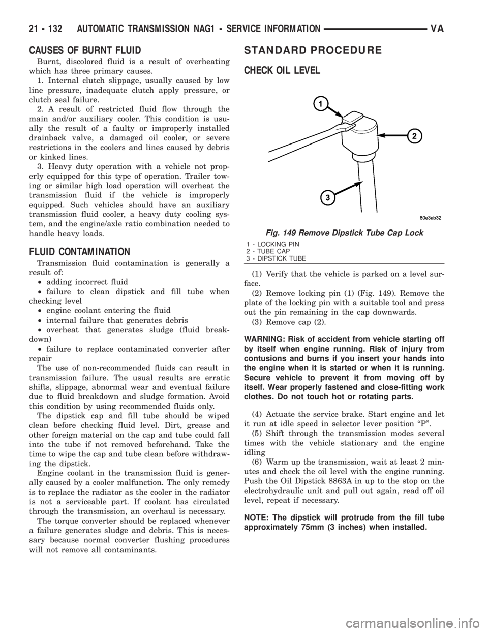
(2) Remove locking pin (1) (Fig. 149). Remove the
plate of the locking pin with a suitable tool and press
out the pin remaining in the cap downwards.
(3) Remove cap (2).
WARNING: Risk of accident from vehicle starting off
by itself when engine running. Risk of injury from
contusions and burns if you insert your hands into
the engine when it is started or when it is running.
Secure vehicle to prevent it from moving off by
itself. Wear properly fastened and close-fitting work
clothes. Do not touch hot or rotating parts.
(4) Actuate the service brake. Start engine and let
it run at idle speed in selector lever position ªPº.
(5) Shift through the transmission modes several
times with the vehicle stationary and the engine
idling
(6) Warm up the transmission, wait at least 2 min-
utes and check the oil level with the engine running.
Push the Oil Dipstick 8863A in up to the stop on the
electrohydraulic unit and pull out again, read off oil
level, repeat if necessary.
NOTE: The dipstick will protrude from the fill tube
approximately 75mm (3 inches) when installed.
Fig. 149 Remove Dipstick Tube Cap Lock
1 - LOCKING PIN
2 - TUBE CAP
3 - DIPSTICK TUBE
21 - 132 AUTOMATIC TRANSMISSION NAG1 - SERVICE INFORMATIONVA
Page 1944 of 2305
BODY
TABLE OF CONTENTS
page page
BODY
WARNING
SAFETY PRECAUTIONS AND WARNINGS . . . 1
DIAGNOSIS AND TESTING
DIAGNOSIS AND TESTING - WATER LEAKS . 1
DIAGNOSIS AND TESTING - WIND NOISE . . . 2
STANDARD PROCEDURE
STANDARD PROCEDURE - PLASTIC BODY
PANEL REPAIR........................3
STANDARD PROCEDURE - BUZZ, SQUEAK
& RATTLE...........................10
SPECIFICATIONS.......................11DOOR - FRONT..........................13
DOORS - REAR..........................23
DOORS - SLIDING........................35
EXTERIOR..............................48
HOOD.................................51
INSTRUMENT PANEL.....................55
INTERIOR..............................70
PAINT.................................77
SEATS.................................79
STATIONARY GLASS.....................84
WEATHERSTRIP/SEALS...................90
BODY STRUCTURE.......................91
BODY
WARNING
SAFETY PRECAUTIONS AND WARNINGS
WARNING: USE AN OSHA APPROVED BREATHING
FILTER WHEN SPRAYING PAINT OR SOLVENTS IN
A CONFINED AREA. PERSONAL INJURY CAN
RESULT.
²AVOID PROLONGED SKIN CONTACT WITH
PETROLEUM OR ALCOHOL ± BASED CLEANING
SOLVENTS. PERSONAL INJURY CAN RESULT.
²DO NOT STAND UNDER A HOISTED VEHICLE
THAT IS NOT PROPERLY SUPPORTED ON SAFETY
STANDS. PERSONAL INJURY CAN RESULT.
CAUTION: When holes must be drilled or punched
in an inner body panel, verify depth of space to the
outer body panel, electrical wiring, or other compo-
nents. Damage to vehicle can result.
²Do not weld exterior panels unless combustible
material on the interior of vehicle is removed from
the repair area. Fire or hazardous conditions, can
result.
²Always have a fire extinguisher ready for use
when welding.
²Disconnect the negative (-) cable clamp from
the battery when servicing electrical components
that are live when the ignition is OFF. Damage to
electrical system can result.
²Do not use abrasive chemicals or compounds
on painted surfaces. Damage to finish can result.²Do not use harsh alkaline based cleaning sol-
vents on painted or upholstered surfaces. Damage
to finish or color can result.
²Do not hammer or pound on plastic trim panel
when servicing interior trim. Plastic panels can
break.DIAGNOSIS AND TESTING
DIAGNOSIS AND TESTING - WATER LEAKS
Water leaks can be caused by poor sealing,
improper body component alignment, body seam
porosity, missing plugs, or blocked drain holes. Cen-
trifugal and gravitational force can cause water to
drip from a location away from the actual leak point,
making leak detection difficult. All body sealing
points should be water tight in normal wet-driving
conditions. Water flowing downward from the front of
the vehicle should not enter the passenger or luggage
compartment. Moving sealing surfaces will not
always seal water tight under all conditions. At
times, side glass or door seals will allow water to
enter the passenger compartment during high pres-
sure washing or hard driving rain (severe) condi-
tions. Overcompensating on door or glass
adjustments to stop a water leak that occurs under
severe conditions can cause premature seal wear and
excessive closing or latching effort. After completing
a repair, water test vehicle to verify leak has stopped
before returning vehicle to use.
VISUAL INSPECTION BEFORE WATER LEAK TESTS
Verify that floor and body plugs are in place, body
drains are clear, and body components are properly
VABODY 23 - 1
Page 1945 of 2305
aligned and sealed. If component alignment or seal-
ing is necessary, refer to the appropriate section of
this group for proper procedures.
WATER LEAK TESTS
WARNING: DO NOT USE ELECTRIC SHOP LIGHTS
OR TOOLS IN WATER TEST AREA. PERSONAL
INJURY CAN RESULT.
When the conditions causing a water leak have
been determined, simulate the conditions as closely
as possible.
²If a leak occurs with the vehicle parked in a
steady light rain, flood the leak area with an open-
ended garden hose.
²If a leak occurs while driving at highway speeds
in a steady rain, test the leak area with a reasonable
velocity stream or fan spray of water. Direct the
spray in a direction comparable to actual conditions.
²If a leak occurs when the vehicle is parked on an
incline, hoist the end or side of the vehicle to simu-
late this condition. This method can be used when
the leak occurs when the vehicle accelerates, stops or
turns. If the leak occurs on acceleration, hoist the
front of the vehicle. If the leak occurs when braking,
hoist the back of the vehicle. If the leak occurs on left
turns, hoist the left side of the vehicle. If the leak
occurs on right turns, hoist the right side of the vehi-
cle. For hoisting recommendations (Refer to LUBRI-
CATION & MAINTENANCE/HOISTING -
STANDARD PROCEDURE).
WATER LEAK DETECTION
To detect a water leak point-of-entry, do a water
test and watch for water tracks or droplets forming
on the inside of the vehicle. If necessary, remove inte-
rior trim covers or panels to gain visual access to the
leak area. If the hose cannot be positioned without
being held, have someone help do the water test.
Some water leaks must be tested for a considerable
length of time to become apparent. When a leak
appears, find the highest point of the water track or
drop. The highest point usually will show the point of
entry. After leak point has been found, repair the
leak and water test to verify that the leak has
stopped.
Locating the entry point of water that is leaking
into a cavity between panels can be difficult. The
trapped water may splash or run from the cavity,
often at a distance from the entry point. Most water
leaks of this type become apparent after accelerating,
stopping, turning, or when on an incline.
MIRROR INSPECTION METHOD
When a leak point area is visually obstructed, use
a suitable mirror to gain visual access. A mirror canalso be used to deflect light to a limited-access area
to assist in locating a leak point.
BRIGHT LIGHT LEAK TEST METHOD
Some water leaks in the luggage compartment can
be detected without water testing. Position the vehi-
cle in a brightly lit area. From inside the darkened
luggage compartment inspect around seals and body
seams. If necessary, have a helper direct a drop light
over the suspected leak areas around the luggage
compartment. If light is visible through a normally
sealed location, water could enter through the open-
ing.
PRESSURIZED LEAK TEST METHOD
When a water leak into the passenger compart-
ment cannot be detected by water testing, pressurize
the passenger compartment and soap test exterior of
the vehicle. To pressurize the passenger compart-
ment, close all doors and windows, start engine, and
set heater control to high blower in HEAT position. If
engine can not be started, connect a charger to the
battery to ensure adequate voltage to the blower.
With interior pressurized, apply dish detergent solu-
tion to suspected leak area on the exterior of the
vehicle. Apply detergent solution with spray device or
soft bristle brush. If soap bubbles occur at a body
seam, joint, seal or gasket, the leak entry point could
be at that location.
DIAGNOSIS AND TESTING - WIND NOISE
Wind noise is the result of most air leaks. Air leaks
can be caused by poor sealing, improper body compo-
nent alignment, body seam porosity, or missing plugs
in the engine compartment or door hinge pillar areas.
All body sealing points should be airtight in normal
driving conditions. Moving sealing surfaces will not
always seal airtight under all conditions. At times,
side glass or door seals will allow wind noise to be
noticed in the passenger compartment during high
cross winds. Over compensating on door or glass
adjustments to stop wind noise that occurs under
severe conditions can cause premature seal wear and
excessive closing or latching effort. After a repair pro-
cedure has been performed, test vehicle to verify
noise has stopped before returning vehicle to use.
VISUAL INSPECTION BEFORE TESTS
Verify that floor and body plugs are in place and
body components are aligned and sealed. If compo-
nent alignment or sealing is necessary, refer to the
appropriate section of this group for proper proce-
dures.
ROAD TESTING WIND NOISE
(1) Drive the vehicle to verify the general location
of the wind noise.
23 - 2 BODYVA