2006 MERCEDES-BENZ SPRINTER air condition
[x] Cancel search: air conditionPage 1629 of 2305
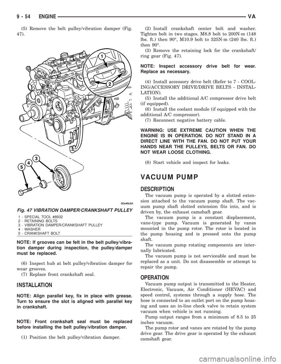
(5) Remove the belt pulley/vibration damper (Fig.
47).
NOTE: If grooves can be felt in the belt pulley/vibra-
tion damper during inspection, the pulley/damper
must be replaced.
(6) Inspect hub at belt pulley/vibration damper for
wear grooves.
(7) Replace front crankshaft seal.
INSTALLATION
NOTE: Align parallel key, fix in place with grease.
Turn to ensure the slot is aligned with parallel key
in crankshaft.
NOTE: Front crankshaft seal must be replaced
before installing the belt pulley/vibration damper.
(1) Position the belt pulley/vibration damper.(2) Install crankshaft center bolt and washer.
Tighten bolt in two stages. M8.8 bolt to 200N´m (148
lbs. ft.) then 90É, M10.9 bolt to 325N´m (240 lbs. ft.)
then 90É.
(3) Remove the retaining lock for the crankshaft/
ring gear (Fig. 47).
NOTE: Inspect accessory drive belt for wear.
Replace as necessary.
(4) Install accessory drive belt (Refer to 7 - COOL-
ING/ACCESSORY DRIVE/DRIVE BELTS - INSTAL-
LATION).
(5) Install the additional A/C compressor drive belt
(if equipped).
(6) Install the coolant module (if equipped with the
additional A/C compressor).
(7) Reconnect negative battery cable.
WARNING: USE EXTREME CAUTION WHEN THE
ENGINE IS IN OPERATION. DO NOT STAND IN A
DIRECT LINE WITH THE FAN. DO NOT PUT YOUR
HANDS NEAR THE PULLEYS, BELTS OR FAN. DO
NOT WEAR LOOSE CLOTHING.
(8) Start vehicle and inspect for leaks.
VACUUM PUMP
DESCRIPTION
The vacuum pump is operated by a slotted exten-
sion attached to the vacuum pump shaft. The vac-
uum pump shaft slotted extension fits into, and is
driven by, the exhaust camshaft gear.
The vacuum pump is a constant displacement,
vane-type pump. Vacuum is generated by vanes
mounted in the pump rotor. The rotor is located in
the pump housing and is pressed onto the pump
shaft.
The vacuum pump rotating components are inter-
nally lubricated.
The vacuum pump is not serviceable and must be
replaced as a unit. Do not disassemble or attempt to
repair the pump.
OPERATION
Vacuum pump output is transmitted to the Heater,
Electronic, Vacuum, Air Conditioner (HEVAC) and
speed control, systems through a supply hose. The
hose is connected to an outlet port on the pump hous-
ing and uses an in-line check valve to retain system
vacuum when vehicle is not running.
Pump output ranges from a minimum of 8.5 to 25
inches vacuum.
The pump rotor and vanes are rotated by the pump
drive gear. The drive gear is operated by the exhaust
camshaft gear.
Fig. 47 VIBRATION DAMPER/CRANKSHAFT PULLEY
1 - SPECIAL TOOL #8932
2 - RETAINING BOLTS
3 - VIBRATION DAMPER/CRANKSHAFT PULLEY
4 - WASHER
5 - CRANKSHAFT BOLT
9 - 54 ENGINEVA
Page 1645 of 2305
(8) Install the exhaust hanger fasteners at the
muffler.
(9) Tighten the exhaust hanger bracket to engine
block.
(10) Install the turbocharger support bracket.
(11) Lower the vehicle.
(12) Install the air cleaner duct to the turbo-
charger (Fig. 71).
(13) Install the exhaust heat shield.
(14) Connect the negative battery cable.
TIMING CHAIN COVER
REMOVAL
WARNING: DO NOT OPEN COOLING SYSTEM
UNLESS TEMPERATURE IS BELOW 90ÉC (194ÉF).
OPEN CAP SLOWLY TO RELEASE PRESSURE.
STORE COOLANT IN APPROVED CONTAINER
ONLY. RISK OF INJURY TO SKIN AND EYES FROM
SCALDING COOLANT. WEAR PROTECTIVE
GLOVES, CLOTHING AND EYE WEAR.
(1) Disconnect negative battery cable.
NOTE: Rotate engine on crankshaft. DO NOT crank
the engine at the bolt of the camshaft sprocket.
NOTE: DO NOT crank engine back.
(2) Position piston of cylinder 1 to ignition TDC.
Markings on the camshaft bearing cap must be
aligned.
(3) Drain coolant (Refer to 7 - COOLING/ENGINE/
COOLANT - STANDARD PROCEDURE).
(4) Install retaining lock for crankshaft/starter
ring gear (Refer to 9 - ENGINE/ENGINE BLOCK/
FLEX PLATE - INSTALLATION).
(5) Drain engine oil.
(6) Remove the oil filter to allow the oil to flow off
into the oil pan.
(7) Remove the radiator assembly (Refer to 7 -
COOLING/ENGINE/RADIATOR - REMOVAL).
(8) Remove engine cover (Refer to 9 - ENGINE -
REMOVAL).
(9) Remove front cover at cylinder head (Refer to 9
- ENGINE/CYLINDER HEAD - REMOVAL).
(10) Remove accessory drive belt.
(11) Remove the high pressure fuel pump (Refer to
14 - FUEL SYSTEM/FUEL DELIVERY/FUEL PUMP
- REMOVAL).
(12) Remove water pump (Refer to 7 - COOLING/
ENGINE/WATER PUMP - REMOVAL).
(13) Remove accessory drive belt pulley and vibra-
tion damper (Refer to 9 - ENGINE/ENGINE BLOCK/
VIBRATION DAMPER - REMOVAL).
(14) Remove the power steering pump.NOTE: NO NOT open the air conditioning system.
(15) Unplug AC compressor electrical connector
and unbolt AC compressor. Relocate in lower engine
compartmentwith outopening the system.
(16) Remove the generator with wiring attached
and relocate somewhere in the engine compartment.
(17) Install engine support fixture.
(18) Remove the oil pan.
(19) Detach the coolant hose to oil-water heat
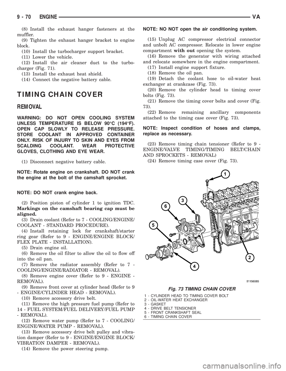
exchanger at crankcase (Fig. 73).
(20) Remove the cylinder head to timing cover
bolts (Fig. 73).
(21) Remove the timing cover bolts and cover (Fig.
73).
(22) Remove remaining ancillary components
attached to the timing case cover (Fig. 73).
NOTE: Inspect condition of hoses and clamps,
replace as necessary.
(23) Remove timing chain tensioner (Refer to 9 -
ENGINE/VALVE TIMING/TIMING BELT/CHAIN
AND SPROCKETS - REMOVAL)
(24) Remove timing case cover (Fig. 73).
Fig. 73 TIMING CHAIN COVER
1 - CYLINDER HEAD TO TIMING COVER BOLT
2 - OIL-WATER HEAT EXCHANGER
3 - GASKET
4 - DRIVE BELT TENSIONER
5 - FRONT CRANKSHAFT SEAL
6 - TIMING CHAIN COVER
9 - 70 ENGINEVA
Page 1646 of 2305
INSTALLATION
CAUTION: Care must be taken to closley inspect
the gasket area around the time case cover to cyl-
inder head gasket coolant port. If damage is found,
replace the cylinder head gasket. Failure to do so
may result in engine damage.
NOTE: Thoroughly clean all mating surfaces with
the appropriate solvents to assure that no grease or
oil is present during assembly.
(1) Inspect cylinder head gasket and oil pan gas-
ket. If damaged, replace.
(2) Replace the front crankshaft seal (Refer to 9 -
ENGINE/ENGINE BLOCK/CRANKSHAFT OIL
SEAL - FRONT - INSTALLATION).
(3) Install ancillary components to timing case
cover.
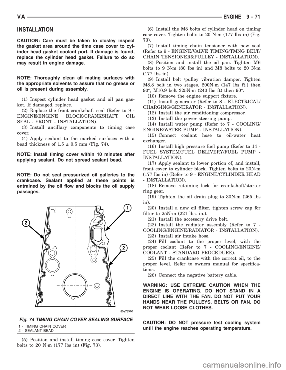
(4) Apply sealant to the marked surfaces with a
bead thickness of 1.5 0.5 mm (Fig. 74).
NOTE: Install timing cover within 10 minutes after
applying sealant. Do not spread sealant bead.
NOTE: Do not seal pressurized oil galleries to the
crankcase. Sealant applied at these points is
entrained by the oil flow and blocks the oil supply
passages.
(5) Position and install timing case cover. Tighten
bolts to 20 N´m (177 lbs in) (Fig. 73).(6) Install the M8 bolts of cylinder head on timing
case cover. Tighten bolts to 20 N´m (177 lbs in) (Fig.
73).
(7) Install timing chain tensioner with new seal
(Refer to 9 - ENGINE/VALVE TIMING/TMNG BELT/
CHAIN TENSIONER&PULLEY - INSTALLATION).
(8) Position and install the oil pan. Tighten M6
bolts to 9 N´m (80 lbs in) and M8 bolts to 20 N´m
(177 lbs in).
(9) Install belt /pulley vibration damper. Tighten
M8.8 bolt in two stages, 200N´m (147 lbs ft.) then
90É, M10.9 bolt 325N´m (240 lbs ft) then 90É.
(10) Remove the engine support fixture.
(11) Install generator (Refer to 8 - ELECTRICAL/
CHARGING/GENERATOR - INSTALLATION).
(12) Install the air conditioning compressor.
(13) Install the power steering pump.
(14) Install water pump (Refer to 7 - COOLING/
ENGINE/WATER PUMP - INSTALLATION).
(15) Connect coolant hose to oil-water heat
exchanger.
(16) Install high pressure fuel pump (Refer to 14 -
FUEL SYSTEM/FUEL DELIVERY/FUEL PUMP -
INSTALLATION).
(17) Apply sealant to lower portion of, and install,
front cover to cylinder block. Tighten bolts to 20N´m
(177 lbs in) (Refer to 9 - ENGINE/CYLINDER HEAD
- INSTALLATION).
(18) Remove retaining lock for crankshaft/starter
ring gear.
(19) Tighten the oil drain plug to 30N´m (265 lbs
in).
(20) Install a new oil filter. tighten screw cap for
filter to 25N´m (221 lbs. in.).
(21) Install the accessory drive belt.
(22) Install the radiator assembly (Refer to 7 -
COOLING/ENGINE/RADIATOR - INSTALLATION).
(23) Install air intake hose.
(24) Fill coolant to the proper level, with the
proper coolant (Refer to 7 - COOLING/ENGINE/
COOLANT - STANDARD PROCEDURE).
(25) Fill the crankcase with the correct oil, to the
proper level. Refer to owners manual for specifica-
tions.
(26) Connect the negative battery cable.
WARNING: USE EXTREME CAUTION WHEN THE
ENGINE IS OPERATING. DO NOT STAND IN A
DIRECT LINE WITH THE FAN. DO NOT PUT YOUR
HANDS NEAR THE PULLEYS, BELTS OR FAN. DO
NOT WEAR LOOSE CLOTHES.
CAUTION: DO NOT pressure test cooling system
until the engine reaches operating temperature.
Fig. 74 TIMING CHAIN COVER SEALING SURFACE
1 - TIMING CHAIN COVER
2 - SEALANT BEAD
VAENGINE 9 - 71
Page 1690 of 2305
(4) Fill fuel tank with fresh diesel fuel.
(5) Drain and remove the fuel filter. (Refer to 14 -
FUEL SYSTEM/FUEL DELIVERY/FUEL FILTER /
WATER SEPARATOR - REMOVAL)
(6) Install a new fuel filter. (Refer to 14 - FUEL
SYSTEM/FUEL DELIVERY/FUEL FILTER / WATER
SEPARATOR - INSTALLATION)
(7) Check the engine control module for any diag-
nostic trouble codes (DTCs). Record and clear any
DTCs that are present.
(8) Start and run the engine. Run the engine for
up to 15 minutes to allow time for any DTCs to reset
and shut off the engine.
(9) Check the engine control module for any diag-
nostic trouble codes (DTCs). Record any DTCs that
are present. Refer to the appropriate engine electrical
diagnostics to diagnose any DTCs that were set.
CAUTION: With the high pressure fuel system in
this vehicle, any residual contaminated fuel will be
removed very quickly. Shut off the engine immedi-
ately if signs of engine damage are noted.The engine should then be evaluated to determine
if the contaminated fuel has caused any damage to
the fuel system and/or engine. Indicators that the
fuel system has been damaged include the following:
²Unstable fuel rail pressure. This can manifest
itself as instability of idle speeds, excessive under-
shoot/overshoot at engine start-up, or excessive
undershoot/overshoot when the engine operating con-
ditions change. A typical engine response to a large
rail pressure undershoot would be a decrease in
engine speed or engine stall.
²Excessive noise from the engine. This could indi-
cate poor rail pressure control or the inability of the
injection system to inject the proper amount of fuel.
²Excessive smoke (black or white). This could
indicate the inability of the fuel system to inject the
proper amount of fuel.
NOTE: If any of these conditions are exhibited after
cleaning the fuel system, proceed to the appropri-
ate engine electrical diagnostic information. Repair
the fuel system and/or engine as necessary.
SPECIFICATIONS
TORQUE
DESCRIPTION N´m Ft. Lbs. In. Lbs.
FUEL TANK MOUNTING NUTS 15 - 17 11 - 13 -
FUEL TANK MODULE LOCKRING (LOCK-
NUT)60 44 -
PRESSURE CONTROL VALVE NUT TO
FUEL RAIL (2 STAGES)60, loosen 90É, re-
tighten to 8044, loosen 90É, re-
tighten to 59-
SPECIAL TOOLS
FUEL SYSTEM
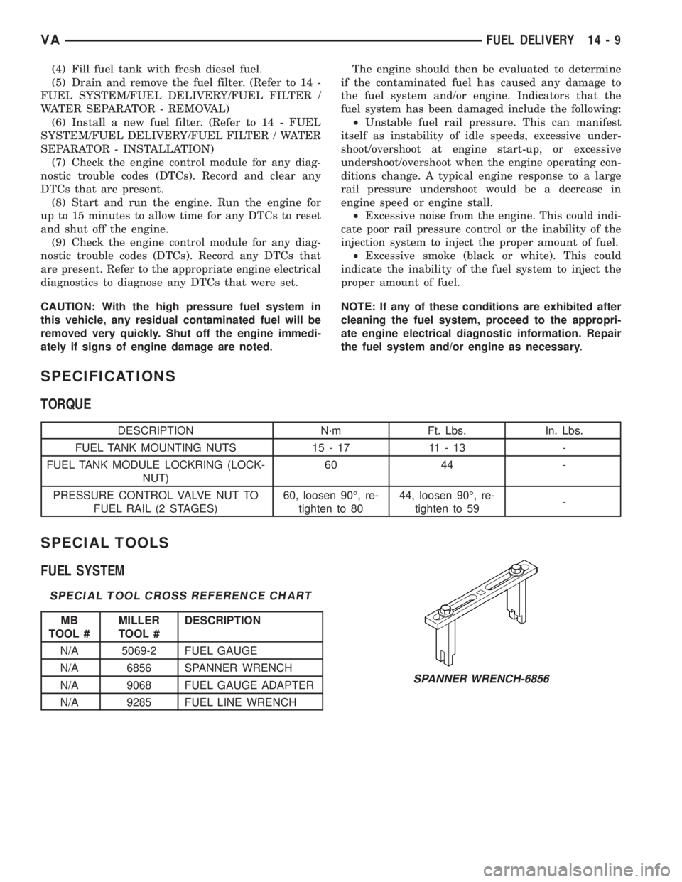
SPECIAL TOOL CROSS REFERENCE CHART
MB
TOOL #MILLER
TOOL #DESCRIPTION
N/A 5069-2 FUEL GAUGE
N/A 6856 SPANNER WRENCH
N/A 9068 FUEL GAUGE ADAPTER
N/A 9285 FUEL LINE WRENCH
SPANNER WRENCH-6856
VAFUEL DELIVERY 14 - 9
Page 1718 of 2305
position against the opening forces applied to its
pressure stage (Fig. 11).
Injector opens (start of injection)
The solenoid valve is energized with the pickup
current which serves to ensure that it open quickly.
The force exerted by the triggered solenoid now
exceeds that of the valve spring and the armature
opens the bleed orifice. Almost immediately, the high-
level pick-up current is reduced to the lower holding
current required for the electromagnet. This is possi-
ble due to the magnetic circuit's air gap now being
smaller. When the bleed orifice opens, fuel can flow
from the valve control chamber into the cavity situ-
ated above it, and from there via the fuel return to
the tank. The bleed orifice prevents complete pres-
sure balance, and the pressure in the valve control
chamber sinks as a result. This leads to the pressure
in the valve-control chamber being lower than that in
the nozzle's chamber volume which is still at the
same pressure level as the rail. The reduced pressure
in the valve-control chamber causes a reduction in
the force exerted on the control plunger, the nozzle
needle open as a result, and injection starts (Fig. 11).
Injector opens fully
The control plunger reaches its upper stop where it
remains supported by a cushion of fuel which is gen-
erated by the flow of fuel between the bleed and feed
orifices. The injector nozzle has now opened fully,
and the fuel is injected into the combustion chamber
at a pressure almost equal to that in the fuel rail
(Fig. 11).
Injector closes (end of injection)
As soon as the solenoid valve is no longer trig-
gered, the valve spring forces the armature down-
wards and the ball closes the bleed orifice. The
armature is a 2±piece design. Here, although the
armature plate is guided by a driver shoulder in its
downward movement, it can ªoverspringº with the
return spring so that it exerts no downwards-acting
forces on the armature and the ball. The closing of
the bleed orifice lead to pressure build up in the con-
trol chamber via the input from the feed orifice. This
pressure is the same as that in the rail and exerts an
increased force on the control plunger through its
end face. This force, together with that of the spring,
now exceeds the force exerted by the chamber volume
and the nozzle needle closes. Injection ceases as soon
as the nozzle needle comes up against its bottom stop
again (Fig. 11).
STANDARD PROCEDURE
STANDARD PROCEDURE - INJECTOR CLASSI-
FICATION
NOTE: Fuel Injectors have different flow rates.
When ALL injectors are removed, re-enter all injec-
tor six digit codes.
The classification of injectors into 3 classes
describes the quantity characteristic of the injector.
This will make it possible in the future to match the
engine software to the tolerances of the injector
within a more narrowly graduated range. Classifica-
tion can be clearly recognized, and assigned only by
means of a DRBIIIt.
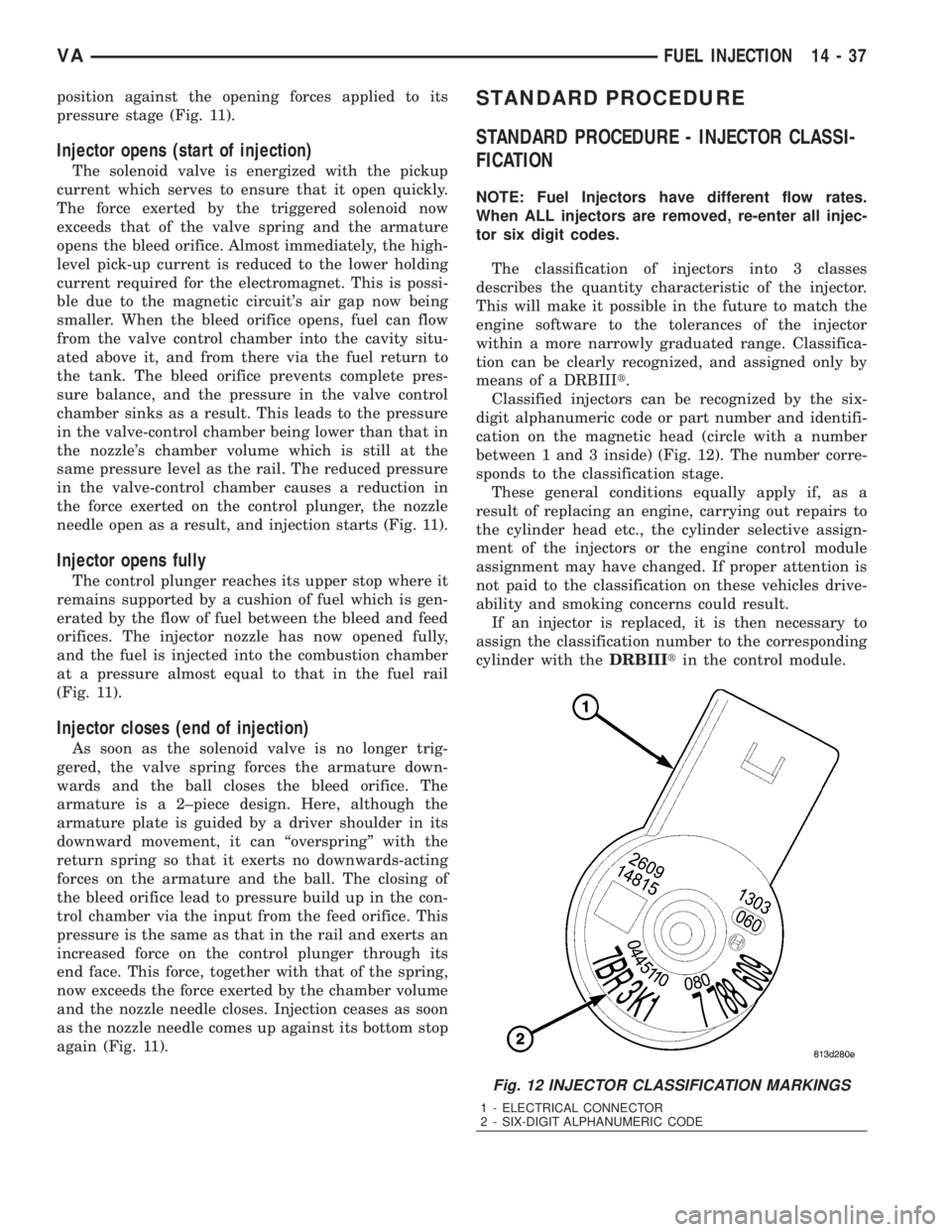
Classified injectors can be recognized by the six-
digit alphanumeric code or part number and identifi-
cation on the magnetic head (circle with a number
between 1 and 3 inside) (Fig. 12). The number corre-
sponds to the classification stage.
These general conditions equally apply if, as a
result of replacing an engine, carrying out repairs to
the cylinder head etc., the cylinder selective assign-
ment of the injectors or the engine control module
assignment may have changed. If proper attention is
not paid to the classification on these vehicles drive-
ability and smoking concerns could result.
If an injector is replaced, it is then necessary to
assign the classification number to the corresponding
cylinder with theDRBIIItin the control module.
Fig. 12 INJECTOR CLASSIFICATION MARKINGS
1 - ELECTRICAL CONNECTOR
2 - SIX-DIGIT ALPHANUMERIC CODE
VAFUEL INJECTION 14 - 37
Page 1723 of 2305
²Tighten the nut to 60 N´m (44 ft. lbs.)
²Loosen the nut 90 degrees.
²Retighten the nut to 80 N´m (59 ft. lbs.).
(3) Install fuel rail (Refer to 14 - FUEL SYSTEM/
FUEL INJECTION/FUEL INJECTOR - INSTALLA-
TION).
(4) Connect negative battery cable.
(5) Start engine, allow to warm, turn engine off
and inspect for leaks (Refer to 14 - FUEL SYSTEM -
DIAGNOSIS AND TESTING).
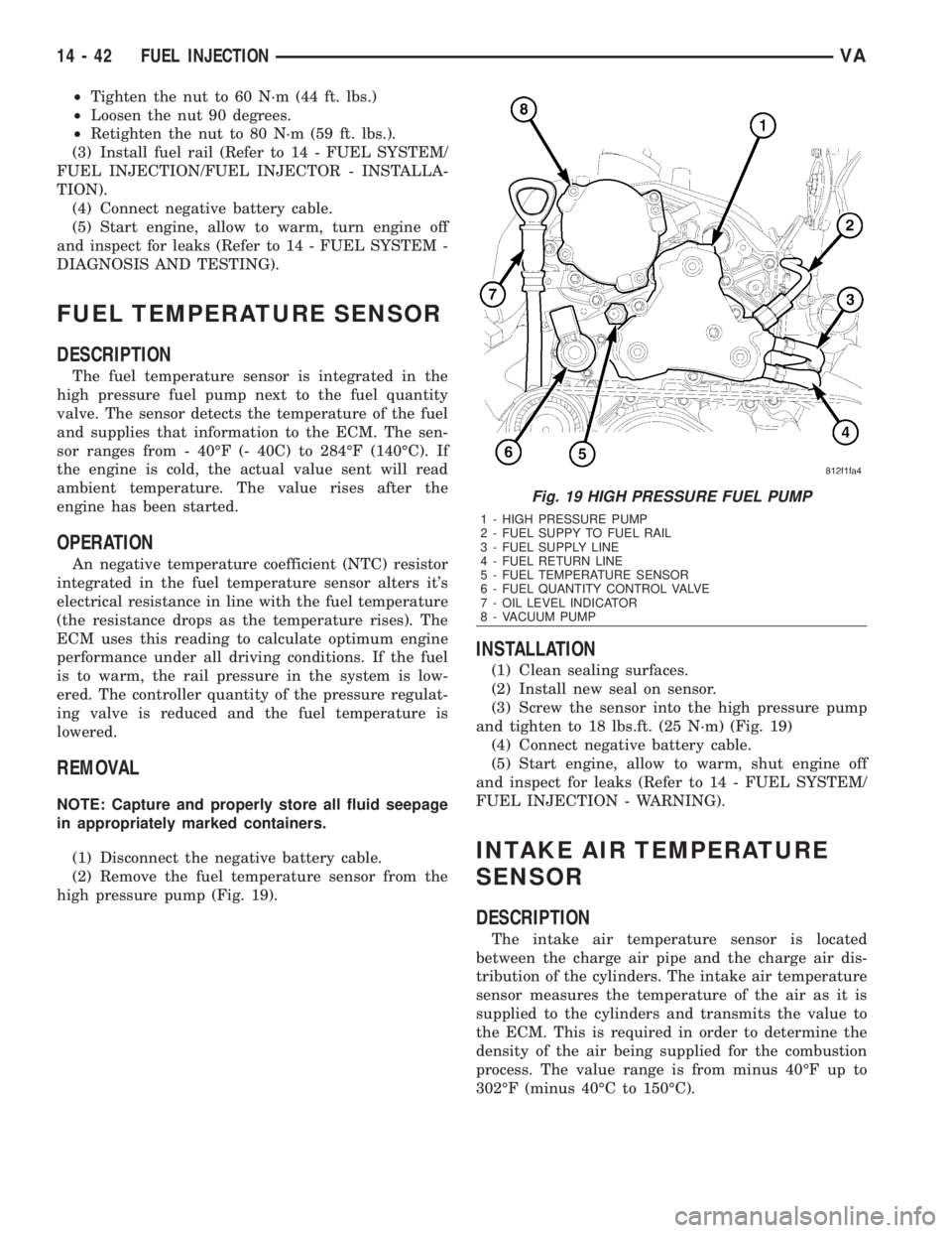
FUEL TEMPERATURE SENSOR
DESCRIPTION
The fuel temperature sensor is integrated in the
high pressure fuel pump next to the fuel quantity
valve. The sensor detects the temperature of the fuel
and supplies that information to the ECM. The sen-
sor ranges from - 40ÉF (- 40C) to 284ÉF (140ÉC). If
the engine is cold, the actual value sent will read
ambient temperature. The value rises after the
engine has been started.
OPERATION
An negative temperature coefficient (NTC) resistor
integrated in the fuel temperature sensor alters it's
electrical resistance in line with the fuel temperature
(the resistance drops as the temperature rises). The
ECM uses this reading to calculate optimum engine
performance under all driving conditions. If the fuel
is to warm, the rail pressure in the system is low-
ered. The controller quantity of the pressure regulat-
ing valve is reduced and the fuel temperature is
lowered.
REMOVAL
NOTE: Capture and properly store all fluid seepage
in appropriately marked containers.
(1) Disconnect the negative battery cable.
(2) Remove the fuel temperature sensor from the
high pressure pump (Fig. 19).
INSTALLATION
(1) Clean sealing surfaces.
(2) Install new seal on sensor.
(3) Screw the sensor into the high pressure pump
and tighten to 18 lbs.ft. (25 N´m) (Fig. 19)
(4) Connect negative battery cable.
(5) Start engine, allow to warm, shut engine off
and inspect for leaks (Refer to 14 - FUEL SYSTEM/
FUEL INJECTION - WARNING).
INTAKE AIR TEMPERATURE
SENSOR
DESCRIPTION
The intake air temperature sensor is located
between the charge air pipe and the charge air dis-
tribution of the cylinders. The intake air temperature
sensor measures the temperature of the air as it is
supplied to the cylinders and transmits the value to
the ECM. This is required in order to determine the
density of the air being supplied for the combustion
process. The value range is from minus 40ÉF up to
302ÉF (minus 40ÉC to 150ÉC).
Fig. 19 HIGH PRESSURE FUEL PUMP
1 - HIGH PRESSURE PUMP
2 - FUEL SUPPY TO FUEL RAIL
3 - FUEL SUPPLY LINE
4 - FUEL RETURN LINE
5 - FUEL TEMPERATURE SENSOR
6 - FUEL QUANTITY CONTROL VALVE
7 - OIL LEVEL INDICATOR
8 - VACUUM PUMP
14 - 42 FUEL INJECTIONVA
Page 1728 of 2305
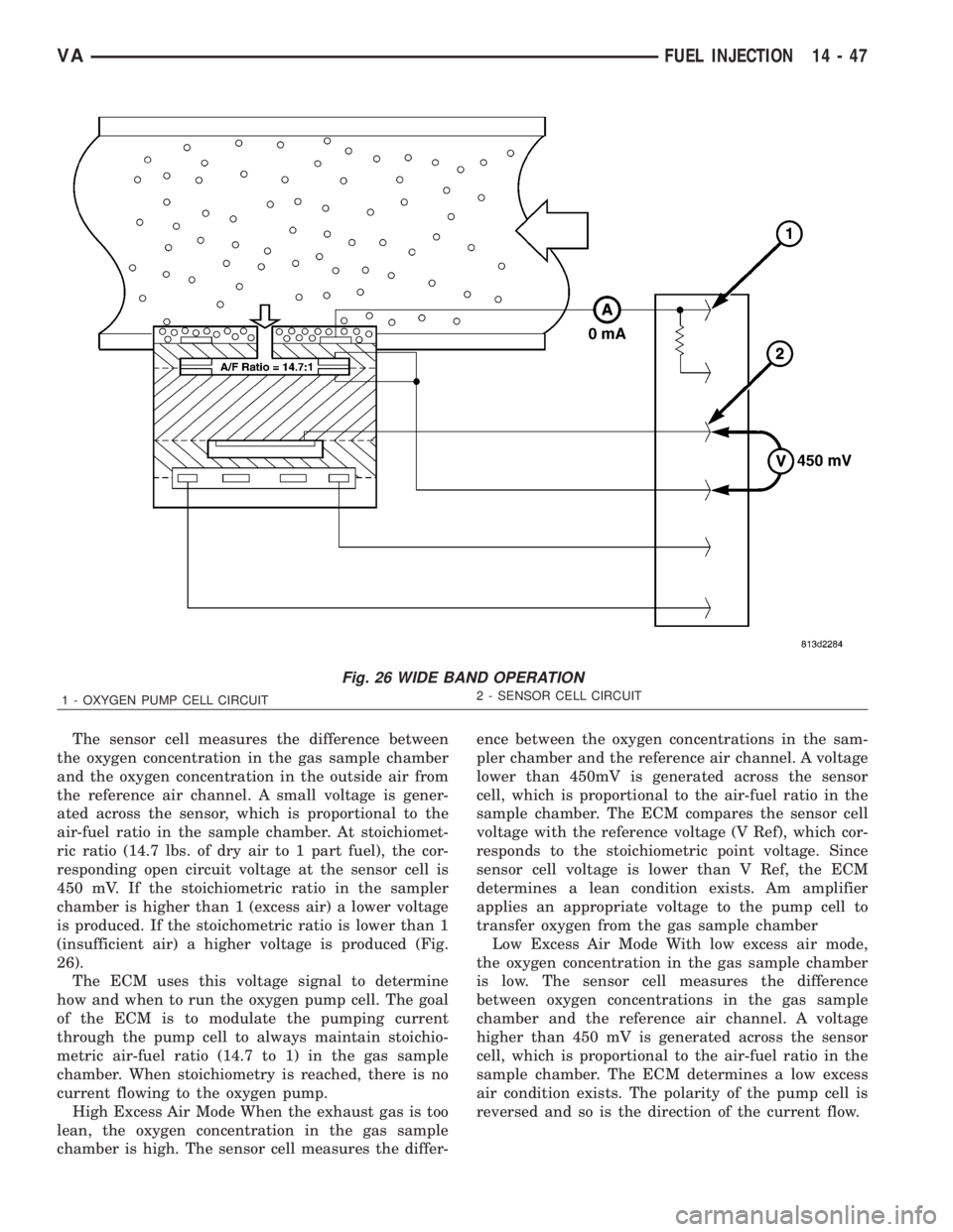
The sensor cell measures the difference between
the oxygen concentration in the gas sample chamber
and the oxygen concentration in the outside air from
the reference air channel. A small voltage is gener-
ated across the sensor, which is proportional to the
air-fuel ratio in the sample chamber. At stoichiomet-
ric ratio (14.7 lbs. of dry air to 1 part fuel), the cor-
responding open circuit voltage at the sensor cell is
450 mV. If the stoichiometric ratio in the sampler
chamber is higher than 1 (excess air) a lower voltage
is produced. If the stoichometric ratio is lower than 1
(insufficient air) a higher voltage is produced (Fig.
26).
The ECM uses this voltage signal to determine
how and when to run the oxygen pump cell. The goal
of the ECM is to modulate the pumping current
through the pump cell to always maintain stoichio-
metric air-fuel ratio (14.7 to 1) in the gas sample
chamber. When stoichiometry is reached, there is no
current flowing to the oxygen pump.
High Excess Air Mode When the exhaust gas is too
lean, the oxygen concentration in the gas sample
chamber is high. The sensor cell measures the differ-ence between the oxygen concentrations in the sam-
pler chamber and the reference air channel. A voltage
lower than 450mV is generated across the sensor
cell, which is proportional to the air-fuel ratio in the
sample chamber. The ECM compares the sensor cell
voltage with the reference voltage (V Ref), which cor-
responds to the stoichiometric point voltage. Since
sensor cell voltage is lower than V Ref, the ECM
determines a lean condition exists. Am amplifier
applies an appropriate voltage to the pump cell to
transfer oxygen from the gas sample chamber
Low Excess Air Mode With low excess air mode,
the oxygen concentration in the gas sample chamber
is low. The sensor cell measures the difference
between oxygen concentrations in the gas sample
chamber and the reference air channel. A voltage
higher than 450 mV is generated across the sensor
cell, which is proportional to the air-fuel ratio in the
sample chamber. The ECM determines a low excess
air condition exists. The polarity of the pump cell is
reversed and so is the direction of the current flow.
Fig. 26 WIDE BAND OPERATION
1 - OXYGEN PUMP CELL CIRCUIT2 - SENSOR CELL CIRCUIT
VAFUEL INJECTION 14 - 47
Page 1731 of 2305
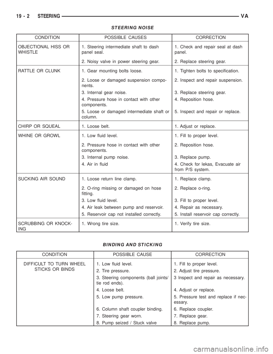
STEERING NOISE
CONDITION POSSIBLE CAUSES CORRECTION
OBJECTIONAL HISS OR
WHISTLE1. Steering intermediate shaft to dash
panel seal.1. Check and repair seal at dash
panel.
2. Noisy valve in power steering gear. 2. Replace steering gear.
RATTLE OR CLUNK 1. Gear mounting bolts loose. 1. Tighten bolts to specification.
2. Loose or damaged suspension compo-
nents.2. Inspect and repair suspension.
3. Internal gear noise. 3. Replace steering gear.
4. Pressure hose in contact with other
components.4. Reposition hose.
5. Loose or damaged intermediate shaft or
column.5. Inspect and repair or replace.
CHIRP OR SQUEAL 1. Loose belt. 1. Adjust or replace.
WHINE OR GROWL 1. Low fluid level. 1. Fill to proper level.
2. Pressure hose in contact with other
components.2. Reposition hose.
3. Internal pump noise. 3. Replace pump.
4. Air in fluid 4. Check for lekas, Evacuate air
from P/S system.
SUCKING AIR SOUND 1. Loose return line clamp. 1. Replace clamp.
2. O-ring missing or damaged on hose
fitting.2. Replace o-ring.
3. Low fluid level. 3. Fill to proper level.
4. Air leak between pump and reservoir. 4. Repair as necessary.
5. Reservoir cap not installed correctly. 5. Install reservoir cap correctly.
SCRUBBING OR KNOCK-
ING1. Wrong tire size. 1. Verify tire size.
BINDING AND STICKING
CONDITION POSSIBLE CAUSE CORRECTION
DIFFICULT TO TURN WHEEL
STICKS OR BINDS1. Low fluid level. 1. Fill to proper level.
2. Tire pressure. 2. Adjust tire pressure.
3. Steering components (ball joints/
tie rod ends).3 Inspect and repair as necessary.
4. Loose belt. 4. Adjust or replace.
5. Low pump pressure. 5. Pressure test and replace if nec-
essary.
6. Column shaft coupler binding. 6. Replace coupler.
7. Steering gear worn. 7. Replace gear.
8. Pump seized / Stuck valve 8. Replace pump.
19 - 2 STEERINGVA