2006 MERCEDES-BENZ SPRINTER air condition
[x] Cancel search: air conditionPage 861 of 2305

rate and boost pressure are adjusted to the actual
injection quantity.
²Injection valve quantity drift compensation in
full load range: this function is to limit the maximum
injection quantity for engine protection. The injection
quantity signal is compared to the injection quantity
calculated from the oxygen sensor signal and MAF
signal. If the comparison shows that the actual injec-
tion quantity is too high, it is limited to the maxi-
mum permissible injection quantity
²Air-fuel ratio controlled smoke limiter (full load):
the smoke limiter limits the injection quantity on the
basis of the air-fuel ratio permissible at the smoke
limit depending on the measure mass air flow and
the calculated EGR rate. As a consequence, the gen-
eration of smoke due to an excess injection quantity
is avoided under all operating conditions. At the
same time, the oxygen sensor signal is used to
ensure that the air-fuel ratio is adjusted accordingly
A function referred to as air flow sensor drift com-
pensation detects and corrects the possible drifting of
the MAF sensor by comparing the air mass measured
by the MAF with the projected air mass as it is cal-
culated by the ECM in consideration of various influ-
encing conditions. It is the air flow drift
compensation that gives the MAF air mass measure-
ment the precision needed to use it for the function
mentioned above. The high precision of the MAF
measurement enables the calculation of the actual
injection quantity from the measured air mass and
from the oxygen sensor signal in order to correct
injection quantity. The MAF signal can also be used
as a input parameter for the smoke limiter.
REMOVAL
(1) Disconnect the negative battery cable.
(2) Disconnect the ECM harness connectors (Fig.
4).
(3) Grasp ECM and pull down firmly to release
ECM from the retaining bracket tensioning springs
(Fig. 4).
INSTALLATION
NOTE: THE ECM MUST BE PROGRAMMED TO SUP-
PORT THE VEHICLE OPTIONS PACKAGE.
(1) Position the ECM into the guide of the retain-
ing bracket (Fig. 4).
(2) Carefully push the ECM in to the bracket until
the bracket tensioning springs engage (Fig. 4).
(3) Connect the ECM wiring harness connectors
(Fig. 4).
(4) Connect negative battery cable.
TRANSMISSION CONTROL
MODULE
DESCRIPTION
The transmission control module (TCM) receives,
processes and sends various digital and analog sig-
nals related to the automatic transmission. In addi-
tion, it processes information received from other
vehicle systems, such as engine torque and speed,
accelerator pedal position, wheel speed, kick-down
switch, traction control information, etc.
The TCM is located under the driver's seat and is
connected to other control modules via a CAN bus. It
controls all shift functions to achieve smooth shift
comfort in all driving situations considering:
²Vehicle speed.
²Transmission status.
Fig. 4 ECM
1 - BRACKET
2 - ECM
3 - BRACKET TENSIONING SPRINGS
8E - 6 ELECTRONIC CONTROL MODULESVA
Page 868 of 2305
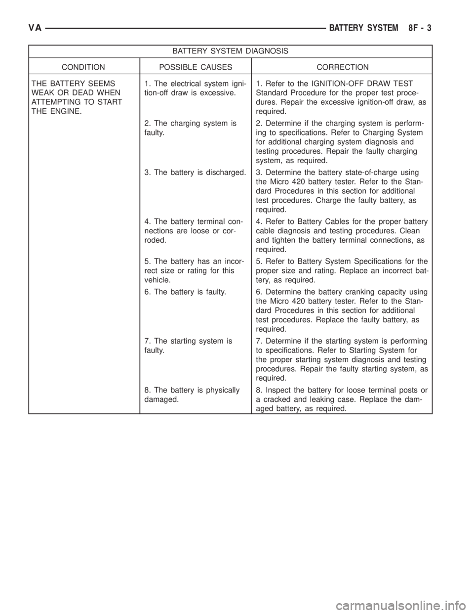
BATTERY SYSTEM DIAGNOSIS
CONDITION POSSIBLE CAUSES CORRECTION
THE BATTERY SEEMS
WEAK OR DEAD WHEN
ATTEMPTING TO START
THE ENGINE.1. The electrical system igni-
tion-off draw is excessive.1. Refer to the IGNITION-OFF DRAW TEST
Standard Procedure for the proper test proce-
dures. Repair the excessive ignition-off draw, as
required.
2. The charging system is
faulty.2. Determine if the charging system is perform-
ing to specifications. Refer to Charging System
for additional charging system diagnosis and
testing procedures. Repair the faulty charging
system, as required.
3. The battery is discharged. 3. Determine the battery state-of-charge using
the Micro 420 battery tester. Refer to the Stan-
dard Procedures in this section for additional
test procedures. Charge the faulty battery, as
required.
4. The battery terminal con-
nections are loose or cor-
roded.4. Refer to Battery Cables for the proper battery
cable diagnosis and testing procedures. Clean
and tighten the battery terminal connections, as
required.
5. The battery has an incor-
rect size or rating for this
vehicle.5. Refer to Battery System Specifications for the
proper size and rating. Replace an incorrect bat-
tery, as required.
6. The battery is faulty. 6. Determine the battery cranking capacity using
the Micro 420 battery tester. Refer to the Stan-
dard Procedures in this section for additional
test procedures. Replace the faulty battery, as
required.
7. The starting system is
faulty.7. Determine if the starting system is performing
to specifications. Refer to Starting System for
the proper starting system diagnosis and testing
procedures. Repair the faulty starting system, as
required.
8. The battery is physically
damaged.8. Inspect the battery for loose terminal posts or
a cracked and leaking case. Replace the dam-
aged battery, as required.
VABATTERY SYSTEM 8F - 3
Page 869 of 2305
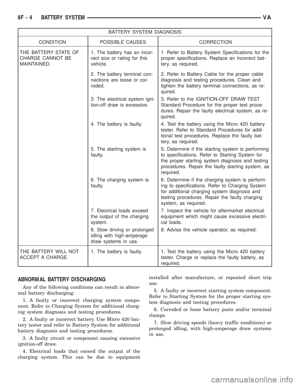
BATTERY SYSTEM DIAGNOSIS
CONDITION POSSIBLE CAUSES CORRECTION
THE BATTERY STATE OF
CHARGE CANNOT BE
MAINTAINED.1. The battery has an incor-
rect size or rating for this
vehicle.1. Refer to Battery System Specifications for the
proper specifications. Replace an incorrect bat-
tery, as required.
2. The battery terminal con-
nections are loose or cor-
roded.2. Refer to Battery Cable for the proper cable
diagnosis and testing procedures. Clean and
tighten the battery terminal connections, as re-
quired.
3. The electrical system igni-
tion-off draw is excessive.3. Refer to the IGNITION-OFF DRAW TEST
Standard Procedure for the proper test proce-
dures. Repair the faulty electrical system, as re-
quired.
4. The battery is faulty. 4. Test the battery using the Micro 420 battery
tester. Refer to Standard Procedures for addi-
tional test procedures. Replace the faulty bat-
tery, as required.
5. The starting system is
faulty.5. Determine if the starting system is performing
to specifications. Refer to Starting System for
the proper starting system diagnosis and testing
procedures. Repair the faulty starting system, as
required.
6. The charging system is
faulty.6. Determine if the charging system is perform-
ing to specifications. Refer to Charging System
for additional charging system diagnosis and
testing procedures. Repair the faulty charging
system, as required.
7. Electrical loads exceed
the output of the charging
system.7. Inspect the vehicle for aftermarket electrical
equipment which might cause excessive electri-
cal loads.
8. Slow driving or prolonged
idling with high-amperage
draw systems in use.8. Advise the vehicle operator, as required.
THE BATTERY WILL NOT
ACCEPT A CHARGE.1. The battery is faulty. 1. Test the battery using the Micro 420 battery
tester. Charge or replace the faulty battery, as
required.
ABNORMAL BATTERY DISCHARGING
Any of the following conditions can result in abnor-
mal battery discharging:
1. A faulty or incorrect charging system compo-
nent. Refer to Charging System for additional charg-
ing system diagnosis and testing procedures.
2. A faulty or incorrect battery. Use Micro 420 bat-
tery tester and refer to Battery System for additional
battery diagnosis and testing procedures.
3. A faulty circuit or component causing excessive
ignition-off draw.
4. Electrical loads that exceed the output of the
charging system. This can be due to equipmentinstalled after manufacture, or repeated short trip
use.
5. A faulty or incorrect starting system component.
Refer to Starting System for the proper starting sys-
tem diagnosis and testing procedures.
6. Corroded or loose battery posts and/or terminal
clamps.
7. Slow driving speeds (heavy traffic conditions) or
prolonged idling, with high-amperage draw systems
in use.
8F - 4 BATTERY SYSTEMVA
Page 894 of 2305
starter pinion gear to spin faster than the pinion
shaft. When the driver releases the ignition switch to
the On position, the starter relay coil is de-energized.
This causes the relay contacts to open. When the
relay contacts open, the starter solenoid plunger
hold-in coil is de-energized.
When the solenoid plunger hold-in coil is de-ener-
gized, the solenoid plunger return spring returns the
plunger to its relaxed position. This causes the con-
tact disc to open the starter feed circuit, and the shift
lever to disengage the overrunning clutch and pinion
gear from the starter ring gear.DIAGNOSIS AND TESTING - STARTING SYS-
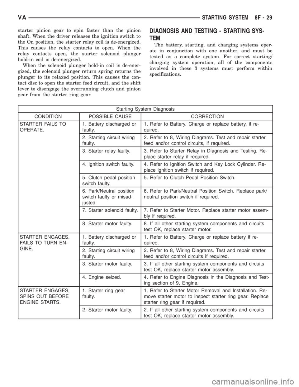
TEM
The battery, starting, and charging systems oper-
ate in conjunction with one another, and must be
tested as a complete system. For correct starting/
charging system operation, all of the components
involved in these 3 systems must perform within
specifications.
Starting System Diagnosis
CONDITION POSSIBLE CAUSE CORRECTION
STARTER FAILS TO
OPERATE.1. Battery discharged or
faulty.1. Refer to Battery. Charge or replace battery, if re-
quired.
2. Starting circuit wiring
faulty.2. Refer to 8, Wiring Diagrams. Test and repair starter
feed and/or control circuits, if required.
3. Starter relay faulty. 3. Refer to Starter Relay in Diagnosis and Testing. Re-
place starter relay if required.
4. Ignition switch faulty. 4. Refer to Ignition Switch and Key Lock Cylinder. Re-
place ignition switch if required.
5. Clutch pedal position
switch faulty.5. Refer to Clutch Pedal Position Switch.
6. Park/Neutral position
switch faulty or misad-
justed.6. Refer to Park/Neutral Position Switch. Replace park/
neutral position switch if required.
7. Starter solenoid faulty. 7. Refer to Starter Motor. Replace starter motor assem-
bly if required.
8. Starter motor faulty. 8. If all other starting system components and circuits
test OK, replace starter motor.
STARTER ENGAGES,
FAILS TO TURN EN-
GINE.1. Battery discharged or
faulty.1. Refer to Battery. Charge or replace battery if re-
quired.
2. Starting circuit wiring
faulty.2. Refer to 8, Wiring Diagrams. Test and repair starter
feed and/or control circuits if required.
3. Starter motor faulty. 3. If all other starting system components and circuits
test OK, replace starter motor assembly.
4. Engine seized. 4. Refer to Engine Diagnosis in the Diagnosis and Test-
ing section of 9, Engine.
STARTER ENGAGES,
SPINS OUT BEFORE
ENGINE STARTS.1. Starter ring gear
faulty.1. Refer to Starter Motor Removal and Installation. Re-
move starter motor to inspect starter ring gear. Replace
starter ring gear if required.
2. Starter motor faulty. 2. If all other starting system components and circuits
test OK, replace starter motor assembly.
VASTARTING SYSTEM 8F - 29
Page 895 of 2305
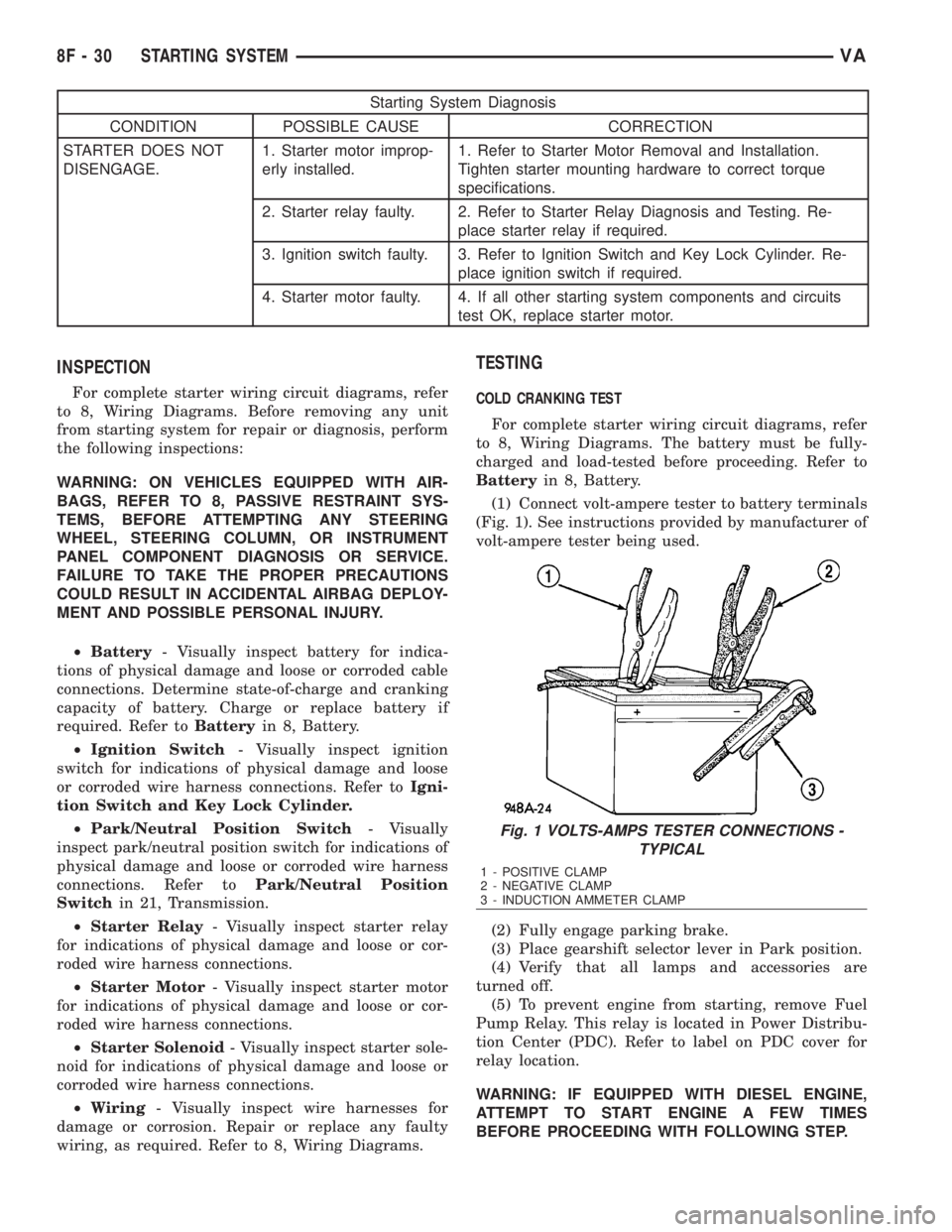
Starting System Diagnosis
CONDITION POSSIBLE CAUSE CORRECTION
STARTER DOES NOT
DISENGAGE.1. Starter motor improp-
erly installed.1. Refer to Starter Motor Removal and Installation.
Tighten starter mounting hardware to correct torque
specifications.
2. Starter relay faulty. 2. Refer to Starter Relay Diagnosis and Testing. Re-
place starter relay if required.
3. Ignition switch faulty. 3. Refer to Ignition Switch and Key Lock Cylinder. Re-
place ignition switch if required.
4. Starter motor faulty. 4. If all other starting system components and circuits
test OK, replace starter motor.
INSPECTION
For complete starter wiring circuit diagrams, refer
to 8, Wiring Diagrams. Before removing any unit
from starting system for repair or diagnosis, perform
the following inspections:
WARNING: ON VEHICLES EQUIPPED WITH AIR-
BAGS, REFER TO 8, PASSIVE RESTRAINT SYS-
TEMS, BEFORE ATTEMPTING ANY STEERING
WHEEL, STEERING COLUMN, OR INSTRUMENT
PANEL COMPONENT DIAGNOSIS OR SERVICE.
FAILURE TO TAKE THE PROPER PRECAUTIONS
COULD RESULT IN ACCIDENTAL AIRBAG DEPLOY-
MENT AND POSSIBLE PERSONAL INJURY.
²Battery- Visually inspect battery for indica-
tions of physical damage and loose or corroded cable
connections. Determine state-of-charge and cranking
capacity of battery. Charge or replace battery if
required. Refer toBatteryin 8, Battery.
²Ignition Switch- Visually inspect ignition
switch for indications of physical damage and loose
or corroded wire harness connections. Refer toIgni-
tion Switch and Key Lock Cylinder.
²Park/Neutral Position Switch- Visually
inspect park/neutral position switch for indications of
physical damage and loose or corroded wire harness
connections. Refer toPark/Neutral Position
Switchin 21, Transmission.
²Starter Relay- Visually inspect starter relay
for indications of physical damage and loose or cor-
roded wire harness connections.
²Starter Motor- Visually inspect starter motor
for indications of physical damage and loose or cor-
roded wire harness connections.
²Starter Solenoid- Visually inspect starter sole-
noid for indications of physical damage and loose or
corroded wire harness connections.
²Wiring- Visually inspect wire harnesses for
damage or corrosion. Repair or replace any faulty
wiring, as required. Refer to 8, Wiring Diagrams.
TESTING
COLD CRANKING TEST
For complete starter wiring circuit diagrams, refer
to 8, Wiring Diagrams. The battery must be fully-
charged and load-tested before proceeding. Refer to
Batteryin 8, Battery.
(1) Connect volt-ampere tester to battery terminals
(Fig. 1). See instructions provided by manufacturer of
volt-ampere tester being used.
(2) Fully engage parking brake.
(3) Place gearshift selector lever in Park position.
(4) Verify that all lamps and accessories are
turned off.
(5) To prevent engine from starting, remove Fuel
Pump Relay. This relay is located in Power Distribu-
tion Center (PDC). Refer to label on PDC cover for
relay location.
WARNING: IF EQUIPPED WITH DIESEL ENGINE,
ATTEMPT TO START ENGINE A FEW TIMES
BEFORE PROCEEDING WITH FOLLOWING STEP.
Fig. 1 VOLTS-AMPS TESTER CONNECTIONS -
TYPICAL
1 - POSITIVE CLAMP
2 - NEGATIVE CLAMP
3 - INDUCTION AMMETER CLAMP
8F - 30 STARTING SYSTEMVA
Page 900 of 2305
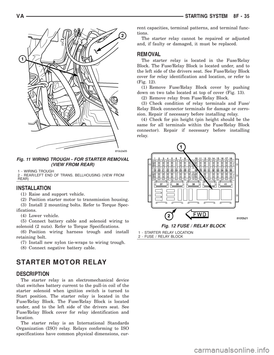
INSTALLATION
(1) Raise and support vehicle.
(2) Position starter motor to transmission housing.
(3) Install 2 mounting bolts. Refer to Torque Spec-
ifications.
(4) Lower vehicle.
(5) Connect battery cable and solenoid wiring to
solenoid (2 nuts). Refer to Torque Specifications.
(6) Position wiring harness trough and install
retaining bolt.
(7) Install new nylon tie-wraps to wiring trough.
(8) Connect negative battery cable.
STARTER MOTOR RELAY
DESCRIPTION
The starter relay is an electromechanical device
that switches battery current to the pull-in coil of the
starter solenoid when ignition switch is turned to
Start position. The starter relay is located in the
Fuse/Relay Block. The Fuse/Relay Block is located
under, and to the left side of the drivers seat. See
Fuse/Relay Block cover for relay identification and
location.
The starter relay is an International Standards
Organization (ISO) relay. Relays conforming to ISO
specifications have common physical dimensions, cur-rent capacities, terminal patterns, and terminal func-
tions.
The starter relay cannot be repaired or adjusted
and, if faulty or damaged, it must be replaced.
REMOVAL
The starter relay is located in the Fuse/Relay
Block. The Fuse/Relay Block is located under, and to
the left side of the drivers seat. See Fuse/Relay Block
cover for relay identification and location, or refer to
(Fig. 12).
(1) Remove Fuse/Relay Block cover by pushing
down on two tabs located at top of cover (Fig. 13).
(2) Remove relay from Fuse/Relay Block.
(3) Check condition of relay terminals and Fuse/
Relay Block connector terminals for damage or corro-
sion. Repair if necessary before installing relay.
(4) Check for pin height (pin height should be the
same for all terminals within the Fuse/Relay Block
connector). Repair if necessary before installing
relay.
Fig. 11 WIRING TROUGH - FOR STARTER REMOVAL
(VIEW FROM REAR)
1 - WIRING TROUGH
2 - REAR/LEFT END OF TRANS. BELLHOUSING (VIEW FROM
REAR)
Fig. 12 FUSE / RELAY BLOCK
1 - STARTER RELAY LOCATION
2 - FUSE / RELAY BLOCK
VASTARTING SYSTEM 8F - 35
Page 912 of 2305

The heated seat system components operate on
battery current received through a fuse in the Fuse
Block on a fused ignition switch output (run-acc) cir-
cuit so that the system will only operate when the
ignition switch is in the On or Accessory positions.
The heated seat system will be turned Off automati-
cally whenever the ignition switch is turned to any
position except On or Accessory. Also, the heated seat
system will not operate when the surface tempera-
ture of the seat cushion cover at either heated seat
sensor is above the designed temperature set points
of the system.DIAGNOSIS AND TESTING - HEATED SEATS
Refer toWiringfor the appropriate wiring infor-
mation. The wiring information includes wiring dia-
grams, proper wire and connector repair procedures,
further details on wire harness routing and reten-
tion, as well as pin-out and location views for the
various wire harness connectors, splices and grounds.
HEATED SEAT SYSTEM DIAGNOSIS
CONDITION POSSIBLE CAUSES CORRECTION
NO HEATED SEAT SWITCH
ILLUMINATION WITH IGNI-
TION ON1. Faulty fuse. 1. Check heated seat fuse in Fuse Block. Re-
place fuse, if required.
2. Wiring faulty. 2. Check fused ignition switch output (run-acc)
circuit from heated seat switch connector to igni-
tion switch. Repair, if required.
3. Ground faulty. 3. Check for ground at heated seat switch con-
nector. Repair, if required.
4. Faulty switch. 4. Refer to Heated Seat Switch for the proper
switch diagnosis and testing procedures.
DRIVER HEATED SEAT
SWITCH
DESCRIPTION
The heated seat switches are located on the instru-
ment panel, in the accessory switch bezel. The two,
momentary rocker type switches provide a signal to
the Heated Seat Relay through separate hard wired
circuits. Each switch contains two light emitting
diodes (LED), one for each High and Low setting to
let the occupant know that the seat heater system is
on.
The heated seat switches and their LED's cannot
be repaired. If either switch is faulty or damaged the
entire switch must be replaced.
OPERATION
There are three modes that can be selected with
each of the heated seat switches: Off, Low, and High.
When the top of the switch rocker is depressed, the
low mode is selected and the low mode LED indicator
illuminates. Depressing the top of the switch rocker a
second time will turn the heated seat to Off. This
same process is repeated for High heat setting. The
heated seats will automatically return to the Off
mode anytime the vehicle ignition switch is turned
Off.Both switches provide separate hard wire inputs to
the Heated Seat Relay to indicate the selected mode.
The Heated Seat Relay responds to the heated seat
switch messages by controlling the output to the seat
heater elements of the selected seat.
DIAGNOSIS AND TESTING - DRIVER HEATED
SEAT SWITCH
For circuit description and diagrams, refer toWir-
ing.
(1) Inspect the Heated Seat Switches for apparent
damage or sticking/binding and replace if required.
Refer to Heated Seat Switch Removal and Installa-
tion in this section.
(2) Replace the heated seat switch with a known
good unit and retest the heated seat system.
REMOVAL
(1) Disconnect and isolate the negative battery
cable.
(2) Remove the gear selector bezel trim. Refer to
the Body section for the procedure.
(3) Remove the storage bin. Refer to the Body sec-
tion for the procedure.
(4) Remove the switch bezel retaining screw and
remove the switch bezel from the instrument panel.
Refer to the Body section for the procedure.
(5) Disconnect electrical connections.
VAHEATED SEATS 8G - 11
Page 922 of 2305

Located between the rear cover and the cluster
hood is the cluster housing. The molded plastic clus-
ter housing serves as the carrier for the cluster elec-
tronic circuit board and circuitry, the cluster
connector receptacles, the gauges, a Light Emitting
Diode (LED) for each cluster indicator and general
illumination lamp, the multi-function indicator LCD
unit, electronic tone generators, the cluster overlay,
the gauge pointers, the multi-function indicator
switches and the four switch push buttons.
The cluster overlay is a laminated plastic unit. The
dark, visible, outer surface of the overlay is marked
with all of the gauge dial faces and graduations, but
this layer is also translucent. The darkness of this
outer layer prevents the cluster from appearing clut-
tered or busy by concealing the cluster indicators
that are not illuminated, while the translucence of
this layer allows those indicators and icons that are
illuminated to be readily visible. The underlying
layer of the overlay is opaque and allows light from
the LED for each of the various indicators and illu-
mination lamps behind it to be visible through the
outer layer of the overlay only through predeter-
mined cutouts. A rectangular opening in the overlay
at the base of the speedometer provides a window
through which the illuminated multi-function indica-
tor LCD unit can be viewed.
Several versions of the EMIC module are offered
on this model. These versions accommodate all of the
variations of optional equipment and regulatory
requirements for the various markets in which the
vehicle will be offered. The microprocessor-based
EMIC utilizes integrated circuitry, Electrically Eras-
able Programmable Read Only Memory (EEPROM)
type memory storage, information carried on the
Controller Area Network (CAN) data bus, along with
several hard wired analog and multiplexed inputs to
monitor systems, sensors and switches throughout
the vehicle.
In response to those inputs, the hardware and soft-
ware of the EMIC allow it to control and integrate
many electronic functions and features of the vehicle
through both hard wired outputs and the transmis-
sion of electronic message outputs to other electronic
modules in the vehicle over the CAN data bus. (Refer
to 8 - ELECTRICAL/ELECTRONIC CONTROL
MODULES/COMMUNICATION - DESCRIPTION -
CAN BUS).
Besides typical instrument cluster gauge and indi-
cator support, the electronic functions and features
that the EMIC supports or controls include the fol-
lowing:
²Active Service System- In vehicles equipped
with the Active Service SYSTem (ASSYST) engine oil
maintenance indicator option, the EMIC electronic
circuit board includes a second dedicated micropro-
cessor. This second microprocessor evaluates various
data including time, mileage, and driving conditionsto calculate the required engine oil service intervals,
and provides both visual and audible alerts to the
vehicle operator when certain engine oil maintenance
services are required.
²Audible Warnings- The EMIC electronic cir-
cuit board is equipped with an audible tone generator
and programming that allows it to provide various
audible alerts to the vehicle operator, including buzz-
ing and chime tones. An audible contactless elec-
tronic relay is also soldered onto the circuit board to
produce audible clicks that is synchronized with turn
signal indicator flashing to emulate the sounds of a
conventional turn signal or hazard warning flasher.
These audible clicks can occur at one of two rates to
emulate both normal and bulb-out turn or hazard
flasher operation. (Refer to 8 - ELECTRICAL/
CHIME/BUZZER - DESCRIPTION).
²Panel Lamps Dimming Control- The EMIC
provides a hard wired 12-volt Pulse-Width Modulated
(PWM) output that synchronizes the dimming level
of all panel lamps dimmer controlled lamps with that
of the cluster general illumination lamps and multi-
function indicator.
The EMIC houses four analog gauges and has pro-
visions for up to nineteen indicators (Fig. 3). The
EMIC includes the following analog gauges:
²Coolant Temperature Gauge
²Fuel Gauge
²Speedometer
²Tachometer
The EMIC includes provisions for the following
indicators (Fig. 3):
²Airbag (SRS) Indicator
²Antilock Brake System (ABS) Indicator
²Brake Indicator
²Brake Wear Indicator
²Charging Indicator
²Clogged Fuel Filter Indicator
²Constant Engine Speed (ADR) Indicator
²Coolant Low Indicator
²Electronic Stability Program (ESP) Indica-
tor
²High Beam Indicator
²Low Fuel Indicator
²Malfunction Indicator Lamp (MIL)
²Multi-Function Indicator (LCD)
²Park Brake Indicator
²Seatbelt Indicator
²Traction Control (ASR) Indicator
²Traction Control (ASR) Malfunction Indica-
tor
²Turn Signal (Right and Left) Indicators
²Washer Fluid Indicator
²Wait-To-Start Indicator
²Water-In-Fuel Indicator
VAINSTRUMENT CLUSTER 8J - 3