2006 MERCEDES-BENZ SPRINTER Windshield
[x] Cancel search: WindshieldPage 723 of 2305
effect panels. If necessary, remove the wheels from
the lifted end of the vehicle and lower the vehicle
closer to the ground, to increase the ground clearance
at the opposite end of the vehicle. Install lug nuts on
wheel attaching studs to retain brake drums.
RAMP ANGLE
If a vehicle with flat-bed towing equipment is used,
the approach ramp angle should not exceed 15
degrees.
TOWING WHEN KEYS ARE NOT AVAILABLE
When the vehicle is locked and keys are not avail-
able, use a flat bed hauler. A Wheel-lift or Sling-type
device can be used provided all the wheels are lifted
off the ground using tow dollies.
MAINTENANCE SCHEDULES
DESCRIPTION
The use of special lubricant additives is not recom-
mended. The use of such additives may affect the
warranty rights. With regard to legal stipulations
concerning emissions control, please note that
engines have to be serviced and adjusted in accor-
dance with special instructions and using special
measuring equipment. Modifications to or interfer-
ence with the emissions control systems are not per-
missible.
MAINTENANCE - WITHOUT ASSYST MAINTE-
NANCE COMPUTER
Maintenance Intervals
²Oil service ±Normal Operationevery 10,000
miles or 16,000 km or 12 months.
²Maintenance service every 30,000 miles or
48,000 km.
Additional work must be carried out at yearly
intervals.
MAINTENANCE - WITH ASSYST MAINTENANCE
COMPUTER
ASSYST provides information on the best possible
timing for maintenance work.
When the next maintenance service is due, this
will be indicated in the multi-function display with
the wrench icon symbol displayed in km/miles or
days.
²One wrench icon showing indicates Oil Service
is necessary.
²Two wrench icons showing indicates Mainte-
nance Service is necessary ± displayed in km/miles or
days.
If the display shows the number of days, a clock
symbol will also appear in the multi-function display.You should have the maintenance performed
within the stated period/distance.
The service indicator will be reset after an oil ser-
vice and/or maintenance service has been performed.
REGULAR CHECK - UPS
To maintain the safe operation of the vehicle, it is
recommended that the following tasks be performed
on a regular basis (i.e. weekly or whenever the vehi-
cle is refueled). Check:
²Engine oil level
²Brake system - fluid level
²Battery - acid level
²Windshield washer system and headlamp clean-
ing system - fluid level
²Mechanical assemblies (e.g. engine, transmis-
sion, etc.) - check for leaks
²Condition of tires and tires pressures
²All exterior lights
SPECIAL MAINTENANCE REQUIREMENTS
If bodies built by manufacturers other than
DaimlerChrysler Corporation are fitted to the vehi-
cle, the maintenance requirements and lubrication
intervals specified by the body manufacturer must be
adhered to, in addition to all standard maintenance
requirements.
Coolant
Corrosion inhibitor/antifreeze concentration in the
coolant should be checked before the onset of winter
(once year in countries with high prevailing temper-
atures).
Replace the coolant every five years or 100,000
miles.
Dust Filter for Heating / Ventilation Replacement
The dust filter and the tailgate interior filter are to
be renewed during routine maintenance service. If
operating conditions are dusty, these filters should be
renewed more frequently.
ENGINE OIL CHANGE AND FILTER REPLACEMENT
At a minimum, change the engine oil and oil filter
once a year ± even if the vehicle mileage per year is
extremely low. For standard oil service schedules
refer to the chapter oil service and maintenance ser-
vice.
Once a Year
Select the viscosity of the engine oil (SAE classes)
according to the outside air temperature.
Only use engine oil approved by DaimlerChrysler
Corporation if following the ASSYST system guide-
lines.
0 - 8 LUBRICATION & MAINTENANCEVA
Page 724 of 2305

SCOPE OF WORK FOR MAINTENANCE SERVICE
Oil Service
²Engine: Oil change and filter replacement
Check fluid levels of the following system, refill as neces-
sary.
²If fluid is lost, trace and eliminate cause - as a
separate order.
²Power-assisted steering
Lubrication work:
²Trailer tow hitch (original equipment)
Maintenance
²ASSYST maintenance computer reset
Function check
²Signalling system, warning and indicator lamps
²Headlamps, exterior lighting
²Windshield wipers, windshield washer system
Check for leaks and damage
²Check for abrasion points and ensure that lines
are correctly routed!
²All lines and hoses, sensor cables
²Rubber boots on front axle drive shafts, rubber
boots on front axle suspension ball joints, shock
absorbers
²Check fluid levels for the following systems, cor-
rect as necessary
NOTE: Should there be a loss of fluid which cannot
be explained by regular use, trace and eliminate the
cause.
²Engine cooling system. Check corrosion inhibi-
tor/antifreeze, refill as necessary.
²Hydraulic brake system
²Battery
²Windshield washer system
Engine
²Fuel filter renewal - Every oil service
²Air cleaner with maintenance indicator:
²Check degree of contamination.
²Air cleaner filter element renewed as necessary.
Chassis and body
²Trailer coupling: Check operation, play and
retaining fixtures
²Secondary rubber springs: Visual check
²Tire pressures: Correct as necessary, including
spare tire
²Check thickness of brake pads
²Brake test
²Check condition of steering mechanism
²Heating/ventilation dust filter renewal
ADDITIONAL MAINTENANCE WORK
Automatic transmission once only at 80,000 miles / 128000
km
²Oil and filter change
During every second maintenance service
²Air cleaner without maintenance indicator:
²Air cleaner filter element renewal
²Check poly-V-belt for wear and signs of damage
During every fourth maintenance service
²Change rear axle fluid
ADDITIONAL MAINTENANCE WORK AFTER YEARS
Every 2 years
²Change brake fluid.
Every 3 years
²Air cleaner filter element renewal (note installa-
tion date)
Every 15 years or 100,000 miles
²Coolant renewal
²Note coolant composition
INTERNATIONAL SYMBOLS
DESCRIPTION
DaimlerChrysler Corporation uses international
symbols to identify engine compartment lubricant
and fluid inspection and fill locations (Fig. 3).
Fig. 3 INTERNATIONAL SYMBOLS
VALUBRICATION & MAINTENANCE 0 - 9
Page 850 of 2305
AUDIO / VIDEO
TABLE OF CONTENTS
page page
AUDIO
SPECIAL TOOLS
AUDIO...............................1
ANTENNA BODY & CABLE
REMOVAL.............................1
INSTALLATION..........................1
INSTRUMENT PANEL ANTENNA CABLE
REMOVAL.............................2INSTALLATION..........................2
RADIO
REMOVAL.............................2
INSTALLATION..........................2
SPEAKER
REMOVAL.............................2
INSTALLATION..........................3
AUDIO
SPECIAL TOOLS
AUDIO
SPECIAL TOOL CROSS REFERENCE CHART
MB
TOOL #MILLER
TOOL #DESCRIPTION
000 589
88 63 009241 RADIO EXTRACTION
TOOL
ANTENNA BODY & CABLE
REMOVAL
(1) Disconnect and isolate the battery negative
cable.
(2) Remove the portion of the headliner over the
front seat passengers (Refer to 23 - BODY/INTERI-
OR/HEADLINER - REMOVAL).
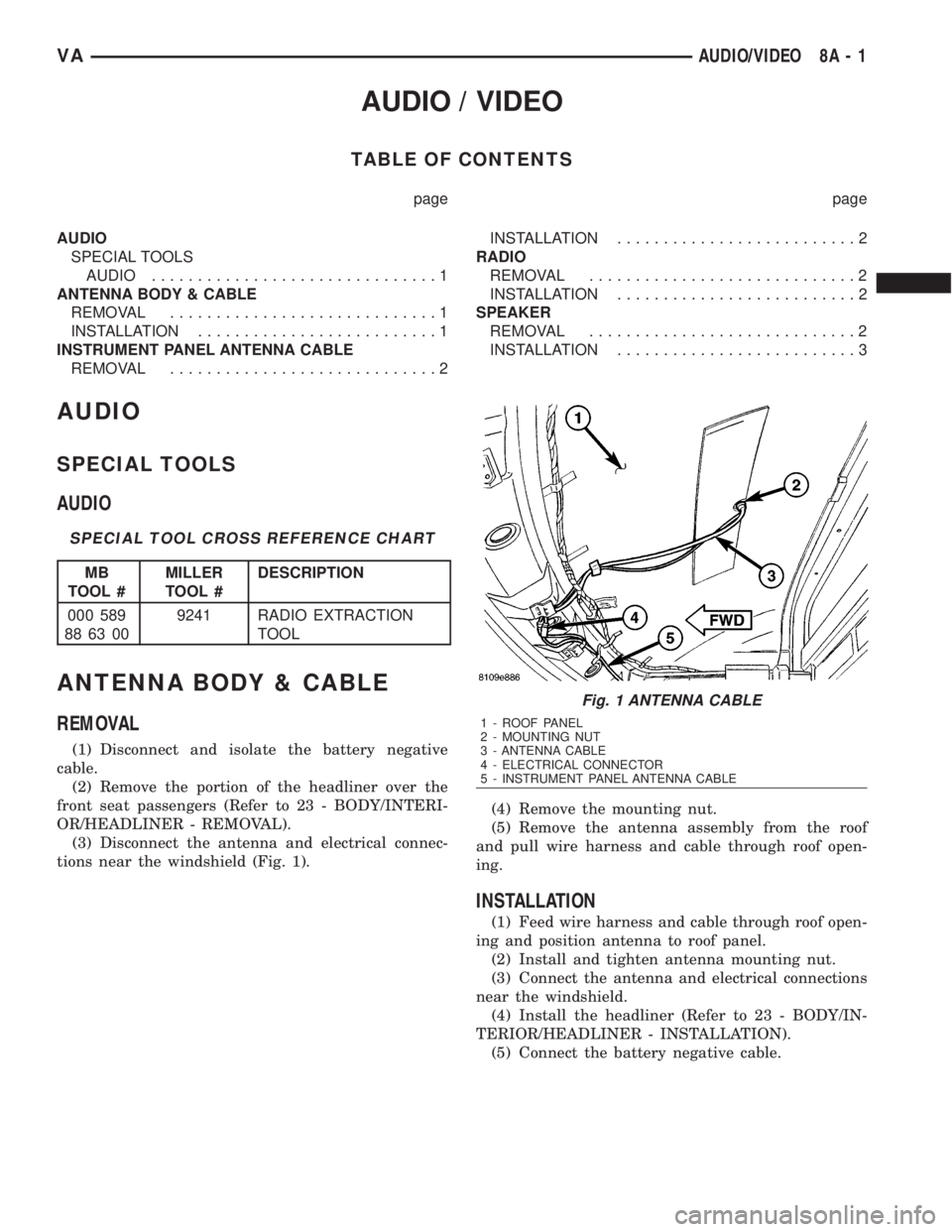
(3) Disconnect the antenna and electrical connec-
tions near the windshield (Fig. 1).(4) Remove the mounting nut.
(5) Remove the antenna assembly from the roof
and pull wire harness and cable through roof open-
ing.
INSTALLATION
(1) Feed wire harness and cable through roof open-
ing and position antenna to roof panel.
(2) Install and tighten antenna mounting nut.
(3) Connect the antenna and electrical connections
near the windshield.
(4) Install the headliner (Refer to 23 - BODY/IN-
TERIOR/HEADLINER - INSTALLATION).
(5) Connect the battery negative cable.
Fig. 1 ANTENNA CABLE
1 - ROOF PANEL
2 - MOUNTING NUT
3 - ANTENNA CABLE
4 - ELECTRICAL CONNECTOR
5 - INSTRUMENT PANEL ANTENNA CABLE
VAAUDIO/VIDEO 8A - 1
Page 851 of 2305
INSTRUMENT PANEL
ANTENNA CABLE
REMOVAL
(1) Disconnect and isolate the battery negative
cable.
(2) Remove the A-pillar trim (Refer to 23 - BODY/
INTERIOR/A-PILLAR TRIM - REMOVAL).
(3) Remove the portion of the headliner over the
front seat passengers (Refer to 23 - BODY/INTERI-
OR/HEADLINER - REMOVAL).
(4) Disconnect the antenna and electrical connec-
tions near the windshield.
(5) Remove the glove box (Refer to 23 - BODY/IN-
STRUMENT PANEL/GLOVE BOX - REMOVAL).
(6) Remove the radio (Refer to 8 - ELECTRICAL/
AUDIO/RADIO - REMOVAL).
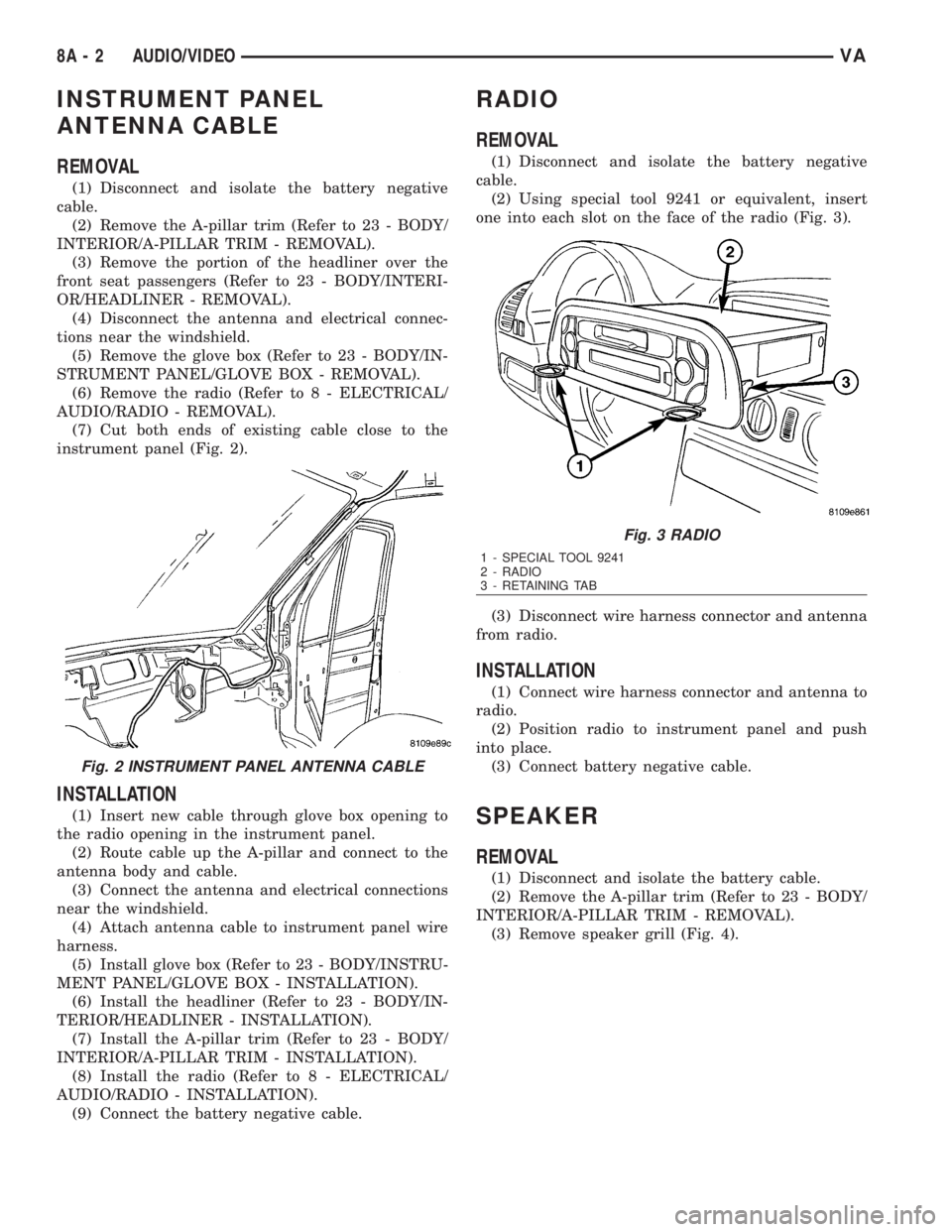
(7) Cut both ends of existing cable close to the
instrument panel (Fig. 2).
INSTALLATION
(1) Insert new cable through glove box opening to
the radio opening in the instrument panel.
(2) Route cable up the A-pillar and connect to the
antenna body and cable.
(3) Connect the antenna and electrical connections
near the windshield.
(4) Attach antenna cable to instrument panel wire
harness.
(5) Install glove box (Refer to 23 - BODY/INSTRU-
MENT PANEL/GLOVE BOX - INSTALLATION).
(6) Install the headliner (Refer to 23 - BODY/IN-
TERIOR/HEADLINER - INSTALLATION).
(7) Install the A-pillar trim (Refer to 23 - BODY/
INTERIOR/A-PILLAR TRIM - INSTALLATION).
(8) Install the radio (Refer to 8 - ELECTRICAL/
AUDIO/RADIO - INSTALLATION).
(9) Connect the battery negative cable.
RADIO
REMOVAL
(1) Disconnect and isolate the battery negative
cable.
(2) Using special tool 9241 or equivalent, insert
one into each slot on the face of the radio (Fig. 3).
(3) Disconnect wire harness connector and antenna
from radio.
INSTALLATION
(1) Connect wire harness connector and antenna to
radio.
(2) Position radio to instrument panel and push
into place.
(3) Connect battery negative cable.
SPEAKER
REMOVAL
(1) Disconnect and isolate the battery cable.
(2) Remove the A-pillar trim (Refer to 23 - BODY/
INTERIOR/A-PILLAR TRIM - REMOVAL).
(3) Remove speaker grill (Fig. 4).
Fig. 2 INSTRUMENT PANEL ANTENNA CABLE
Fig. 3 RADIO
1 - SPECIAL TOOL 9241
2 - RADIO
3 - RETAINING TAB
8A - 2 AUDIO/VIDEOVA
Page 948 of 2305

The ECM continually monitors the engine coolant
temperature sensor to determine when the glow
plugs need to be energized in their pre-heat operat-
ing mode. The ECM then sends the proper wait-to-
start lamp-on and lamp-off messages to the
instrument cluster. If the instrument cluster turns on
the indicator after the engine is started, it may indi-
cate that a malfunction has occurred and that the
engine glow control system requires service. The
ECM will store a Diagnostic Trouble Code (DTC) for
any malfunction it detects. For proper diagnosis of
the engine coolant temperature sensor, the engine
glow control system and circuits, the ECM, the CAN
data bus, or the electronic message inputs to the
instrument cluster that control the wait-to-start indi-
cator, a diagnostic scan tool is required. Refer to the
appropriate diagnostic information.
WASHER FLUID INDICATOR
DESCRIPTION
A washer fluid indicator is standard equipment on
all instrument clusters. However, this indicator is
only functional on vehicles equipped with an optional
washer fluid level switch integral to the washer
pump/motor unit on the washer reservoir. The
washer fluid indicator is located near the lower edge
of the instrument cluster, to the right of the multi-
function indicator display. The washer fluid indicator
consists of the International Control and Display
Symbol icon for ªWindshield Washer Fluidº imprinted
within a rectangular cutout in the opaque layer of
the instrument cluster overlay. The dark outer layer
of the overlay prevents the indicator from being
clearly visible when it is not illuminated. An amber
Light Emitting Diode (LED) behind the cutout in the
opaque layer of the overlay causes the icon to appear
silhouetted against an amber field through the trans-
lucent outer layer of the overlay when the indicator
is illuminated from behind by the LED, which is sol-
dered onto the instrument cluster electronic circuit
board. The washer fluid indicator is serviced as a
unit with the instrument cluster.
OPERATION
The washer fluid indicator gives an indication to
the vehicle operator that the fluid level in the washer
reservoir is low. This indicator is controlled by the
instrument cluster circuit board based upon cluster
programming and a hard wired input from the
optional washer fluid level switch that is integral to
the washer pump/motor unit. The washer fluid indi-
cator is completely controlled by the instrument clus-
ter logic circuit, and that logic will only allow this
indicator to operate when the instrument cluster
detects that the ignition switch is in the On position.
Therefore, the indicator will always be off when theignition switch is in any position except On. The indi-
cator only illuminates when it is switched to ground
by the instrument cluster circuitry. The instrument
cluster will turn on the washer fluid indicator for the
following reasons:
²Bulb Test- Each time the ignition switch is
turned to the On position the brake wear indicator is
illuminated by the instrument cluster for about two
seconds as a bulb test.
²Washer Fluid Level Switch Input- Each time
the cluster detects ground on the washer fluid switch
sense circuit (washer fluid level switch closed =
washer fluid level low) while the ignition switch is in
the On position, the washer fluid indicator is illumi-
nated. The indicator remains illuminated until the
washer fluid level switch input to the cluster is an
open circuit (washer fluid level switch open = washer
fluid level acceptable), or until the ignition switch is
turned to the Off position, whichever occurs first.
The instrument cluster continually monitors the
washer fluid level switch to determine the level of
the washer fluid. The instrument cluster logic applies
a delay strategy to this input to reduce the negative
effect that fluid sloshing within the reservoir can
have on reliable indicator operation. The washer
fluid level switch and circuit can be diagnosed using
conventional diagnostic tools and methods. For
proper diagnosis of the instrument cluster circuitry
that controls the washer fluid indicator, a diagnostic
scan tool is required. Refer to the appropriate diag-
nostic information.
WATER - IN - FUEL INDICATOR
DESCRIPTION
A water-in-fuel indicator is standard equipment in
all instrument clusters. The water-in-fuel indicator is
located near the lower edge of the instrument cluster,
to the left of the multi-function indicator display. The
water-in-fuel indicator consists of the International
Control and Display Symbol icon for ªWater In Fuelº
imprinted within a rectangular cutout in the opaque
layer of the instrument cluster overlay. The dark
outer layer of the overlay prevents the indicator from
being clearly visible when it is not illuminated. An
amber Light Emitting Diode (LED) behind the cutout
in the opaque layer of the overlay causes the icon to
appear silhouetted against an amber field through
the translucent outer layer of the overlay when the
indicator is illuminated from behind by the LED,
which is soldered onto the instrument cluster elec-
tronic circuit board. The water-in-fuel indicator is
serviced as a unit with the instrument cluster.
OPERATION
The water-in-fuel indicator gives an indication to
the vehicle operator when there is excessive water
VAINSTRUMENT CLUSTER 8J - 29
Page 977 of 2305

LAMPS / LIGHTING - INTERIOR
TABLE OF CONTENTS
page page
LAMPS/LIGHTING - INTERIOR
DESCRIPTION.........................28
OPERATION...........................29
SPECIFICATIONS - INTERIOR LIGHTING.....29
ASH RECEIVER/CIGAR LIGHTER LAMP UNIT
REMOVAL.............................30
INSTALLATION.........................30
CARGO/DOME LAMP BULB
REMOVAL.............................30
INSTALLATION.........................30
CARGO/DOME LAMP UNIT
REMOVAL.............................31
INSTALLATION.........................31
CARGO LAMP SWITCH
REMOVAL
REMOVAL - INSTRUMENT PANEL........31
REMOVAL - BULKHEAD................31
REMOVAL - REAR PILLAR..............31
INSTALLATION
INSTALLATION - INSTRUMENT PANEL.....32
INSTALLATION - BULKHEAD.............32
INSTALLATION - REAR PILLAR...........32
DOME/READING LAMP BULB
REMOVAL.............................32INSTALLATION.........................32
DOME/READING LAMP UNIT
REMOVAL.............................32
INSTALLATION.........................33
DOME LAMP/INTRUSION SENSOR BULB
REMOVAL.............................33
INSTALLATION.........................33
DOME LAMP/INTRUSION SENSOR
REMOVAL.............................33
INSTALLATION.........................34
DOOR JAMB SWITCH
REMOVAL.............................34
INSTALLATION.........................34
ENTRY/EXIT LAMP BULB
REMOVAL.............................34
INSTALLATION.........................35
ENTRY/EXIT LAMP UNIT
REMOVAL.............................35
INSTALLATION.........................35
TIME DELAY RELAY
REMOVAL.............................35
INSTALLATION.........................36
LAMPS / LIGHTING - INTERIOR
DESCRIPTION
The interior lighting for this model includes the
following standard and optional incandescent interior
lamps and controls:
²Ash Receiver/Cigar Lighter Lamp- An avail-
able ash receiver/cigar lighter lamp is secured by an
integral mount to the outside of the cigar lighter halo
ring. A single lamp serves to illuminate both the
translucent halo ring and the ash receiver.
²Cargo/Dome Lamp- Several cargo/dome lamp
units located overhead in both the front and rear of
the vehicle interior are standard equipment. These
lamps feature a single incandescent bulb. An optional
version of these lamps includes an integral three-po-
sition switch that protrudes through the lamp lens.
²Cargo Lamp Switch- Toggle-type remote
cargo lamp switches located in the accessory switch
bezel in the center of the instrument panel, on the
back side of the cargo compartment bulkhead panel,
and on the rear cargo door pillar are an available
option on all van models. The instrument panel
switch has two Light-Emitting Diode (LED) units,one for illumination and a second that provides an
indication. The switches mounted in the cargo com-
partment also have two LED units, but only the indi-
cation LED unit is functional in this application.
²Dome/Reading Lamp- An optional equipment
dome/reading lamp unit is located in the windshield
header area between the driver and passenger sun
visors. This lamp features two incandescent bulbs,
one dome lamp bulb and a second, dedicated reading
lamp bulb. An integral four-position switch protrudes
through the lamp lens.
²Dome Lamp/Intrusion Sensor- An optional
equipment dome lamp/intrusion sensor unit is
located overhead in the vehicle interior. This lamp
features four incandescent bulbs, two for dome lamps
and two for dedicated right and left reading lamps.
This lamp has two integral three-position switches,
one to control interior lamp operation and one to con-
trol reading lamp operation. This lamp also houses
three intrusion sensors that are part of an optional
vehicle theft security system.
²Door Jamb Switch- A door jamb switch for
each front door is standard equipment on all models.
A door jamb switch for each sliding side door and the
8L - 28 LAMPS/LIGHTING - INTERIORVA
Page 978 of 2305
right rear door is standard equipment on wagon mod-
els. The sliding and rear door jamb switches are not
available for van models.
²Entry/Exit Lamp- An entry/exit lamp to illu-
minate each front and sliding side door step well is
optional equipment on wagon models.
²Time Delay Relay- Vehicles equipped with the
optional remote cargo lamp switches also have a time
delay relay located in the electrical center within the
driver side front seat riser.
Hard wired circuitry connects the interior lighting
system components to the electrical system of the
vehicle. These hard wired circuits are integral to sev-
eral wire harnesses, which are routed throughout the
vehicle and retained by many different methods.
These circuits may be connected to each other, to the
vehicle electrical system and to the interior lighting
system components through the use of a combination
of soldered splices, splice block connectors, and many
different types of wire harness terminal connectors
and insulators. Refer to the appropriate wiring infor-
mation. The wiring information includes wiring dia-
grams, proper wire and connector repair procedures,
further details on wire harness routing and reten-
tion, as well as pin-out and location views for the
various wire harness connectors, splices and grounds.
OPERATION
The interior lighting systems can be divided into
two general classifications based upon the circuit
that controls their operation: The interior lighting
circuit, or the exterior lighting circuit. The hard
wired circuits and components of the interior lighting
systems may be diagnosed and tested using conven-
tional diagnostic tools and procedures.
INTERIOR LIGHTING CIRCUIT
Depending upon the vehicle model (van or wagon)
and the selected vehicle options the interior lighting
circuit may include dome/cargo lamps located over-
head in the front and rear of the vehicle, a dome/
reading lamp located in the header area above the
windshield between the sun visors, and entry/exit
lamps located in the front and sliding side door step
wells.
WAGON MODELS
In all wagon models, the lamps in the interior
lighting circuit are provided with battery current at
all times by a fuse in the fuse block beneath the
steering column. The front, side, and rear door jamb
switches control a ground path for each of these
lamps, except for the optional reading lamp. If the
lamp has an optional integral switch, that switch has
three separate positions. The first position provides a
ground path independent of the door jamb switches
to turn the lamp On. The second, or center position
allows the door jamb switches to control the lamp.The third position segregates that lamp from the
door jamb switch input, turning the lamp Off. In the
case of the optional dome/reading lamp, the integral
lamp switch has a fourth position which will illumi-
nate only the reading lamp bulb.
VAN MODELS
Unless a van model is equipped with an optional
remote cargo lamp switch, all of the lamps in the
interior lighting circuit operate the same way as the
wagon models except that there are only two door
jamb switches, one for each front door. If the vehicle
is equipped with an optional remote cargo lamp
switch, the lamps in the rear of the vehicle on the
interior lighting circuit are provided with battery
current by the time delay relay. The time delay relay
is a smart relay containing active electronic elements
that comprise an electronic timer logic circuit. When
the remote cargo lamp switches provide the proper
input to the time delay relay, the relay logic responds
by energizing the relay control coil. The energized
relay control coil provides battery current to all of
the lamps on the rear interior lighting circuit and to
the indicator Light-Emitting Diode (LED) units in
the remote cargo switches causing each to illuminate.
If a remote cargo lamp switch remains On for more
than about fifteen minutes, the time delay relay will
then automatically de-energize the rear interior
lighting circuits until the remote cargo lamp switch
is cycled Off and then back On.
EXTERIOR LIGHTING CIRCUIT
The exterior lighting circuit provides battery cur-
rent to the optional ash receiver/cigar lighter lamp
and to the illumination Light-Emitting Diode (LED)
unit within the remote cargo lamp switch in the
instrument panel accessory switch bezel whenever
the exterior lamps are turned On.
SPECIFICATIONS - INTERIOR LIGHTING
VALAMPS/LIGHTING - INTERIOR 8L - 29
Page 1024 of 2305
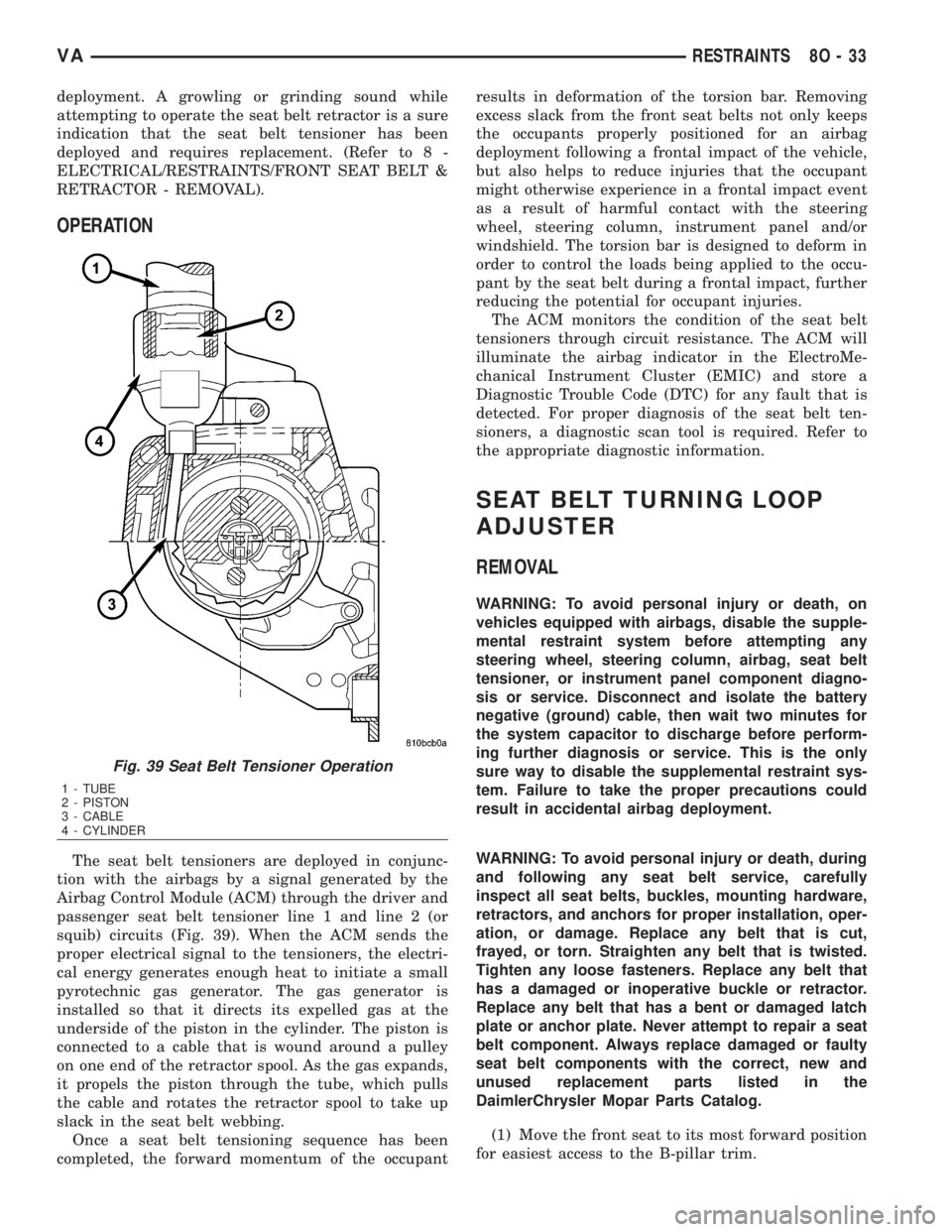
deployment. A growling or grinding sound while
attempting to operate the seat belt retractor is a sure
indication that the seat belt tensioner has been
deployed and requires replacement. (Refer to 8 -
ELECTRICAL/RESTRAINTS/FRONT SEAT BELT &
RETRACTOR - REMOVAL).
OPERATION
The seat belt tensioners are deployed in conjunc-
tion with the airbags by a signal generated by the
Airbag Control Module (ACM) through the driver and
passenger seat belt tensioner line 1 and line 2 (or
squib) circuits (Fig. 39). When the ACM sends the
proper electrical signal to the tensioners, the electri-
cal energy generates enough heat to initiate a small
pyrotechnic gas generator. The gas generator is
installed so that it directs its expelled gas at the
underside of the piston in the cylinder. The piston is
connected to a cable that is wound around a pulley
on one end of the retractor spool. As the gas expands,
it propels the piston through the tube, which pulls
the cable and rotates the retractor spool to take up
slack in the seat belt webbing.
Once a seat belt tensioning sequence has been
completed, the forward momentum of the occupantresults in deformation of the torsion bar. Removing
excess slack from the front seat belts not only keeps
the occupants properly positioned for an airbag
deployment following a frontal impact of the vehicle,
but also helps to reduce injuries that the occupant
might otherwise experience in a frontal impact event
as a result of harmful contact with the steering
wheel, steering column, instrument panel and/or
windshield. The torsion bar is designed to deform in
order to control the loads being applied to the occu-
pant by the seat belt during a frontal impact, further
reducing the potential for occupant injuries.
The ACM monitors the condition of the seat belt
tensioners through circuit resistance. The ACM will
illuminate the airbag indicator in the ElectroMe-
chanical Instrument Cluster (EMIC) and store a
Diagnostic Trouble Code (DTC) for any fault that is
detected. For proper diagnosis of the seat belt ten-
sioners, a diagnostic scan tool is required. Refer to
the appropriate diagnostic information.
SEAT BELT TURNING LOOP
ADJUSTER
REMOVAL
WARNING: To avoid personal injury or death, on
vehicles equipped with airbags, disable the supple-
mental restraint system before attempting any
steering wheel, steering column, airbag, seat belt
tensioner, or instrument panel component diagno-
sis or service. Disconnect and isolate the battery
negative (ground) cable, then wait two minutes for
the system capacitor to discharge before perform-
ing further diagnosis or service. This is the only
sure way to disable the supplemental restraint sys-
tem. Failure to take the proper precautions could
result in accidental airbag deployment.
WARNING: To avoid personal injury or death, during
and following any seat belt service, carefully
inspect all seat belts, buckles, mounting hardware,
retractors, and anchors for proper installation, oper-
ation, or damage. Replace any belt that is cut,
frayed, or torn. Straighten any belt that is twisted.
Tighten any loose fasteners. Replace any belt that
has a damaged or inoperative buckle or retractor.
Replace any belt that has a bent or damaged latch
plate or anchor plate. Never attempt to repair a seat
belt component. Always replace damaged or faulty
seat belt components with the correct, new and
unused replacement parts listed in the
DaimlerChrysler Mopar Parts Catalog.
(1) Move the front seat to its most forward position
for easiest access to the B-pillar trim.
Fig. 39 Seat Belt Tensioner Operation
1 - TUBE
2 - PISTON
3 - CABLE
4 - CYLINDER
VARESTRAINTS 8O - 33