2006 MERCEDES-BENZ SPRINTER Windshield
[x] Cancel search: WindshieldPage 10 of 2305

TABLE OF CONTENTS - Continued
VEHICLE THEFT/SECURITY
DRIVER CYLINDER LOCK SWITCH CIRCUIT SHORT TO GROUND............212
DRIVER CYLINDER UNLOCK SWITCH CIRCUIT SHORT TO GROUND.........214
FRONT DOOR JAMB SWITCH CIRCUIT SHORT TO GROUND................216
INTERNAL ERROR - SSM...............................................218
TOWING INCLINATION SENSOR BEYOND LIMITS..........................218
TOWING INCLINATION SENSOR VALUE IS INVALID.........................218
TOWING INCLINATION SENSOR VALUE IS MISSING........................218
INTRUSION SENSOR 1 CIRCUIT OPEN/SHORT TO GROUND................220
INTRUSION SENSOR 1 GROUND CIRCUIT OPEN..........................222
INTRUSION SENSOR 2 CIRCUIT OPEN/SHORT TO GROUND................223
INTRUSION SENSOR 2 GROUND CIRCUIT OPEN..........................225
INTRUSION SENSOR 3 CIRCUIT OPEN/SHORT TO GROUND................226
INTRUSION SENSOR 3 GROUND CIRCUIT OPEN..........................228
REAR OR SLIDING DOOR JAMB SWITCH CIRCUIT SHORT TO GROUND......229
RKE INTERFACE CIRCUIT FAILURE - SSM................................231
SECURITY SYSTEM INTERFACE FAILURE - SSM...........................233
SIREN CIRCUIT OPEN/SHORTED TO GROUND............................235
SIREN INTERNAL FAILURE.............................................237
SIREN SIGNAL CONTROL CIRCUIT SHORT TO GROUND....................238
WINDSHIELD WIPER & WASHER
CHECKING THE RAIN SENSOR/WIPER OPERATION........................239
VERIFICATION TESTS
VERIFICATION TESTS..................................................244
8.0 COMPONENT LOCATIONS..............................................249
8.1AIRBAG SYSTEM.................................................249
8.2AIRBAG CONTROL MODULE.......................................249
8.3DRIVER AIRBAG SQUIB...........................................249
8.4CLOCKSPRING..................................................250
8.5SEAT BELT TENSIONER...........................................250
8.6HEATING & A/C...................................................250
8.6.1AUTOMATIC TEMPERATURE CONTROL (ATC) SYSTEM
COMPONENTS...........................................250
8.6.2CABIN HEATER & HEATER BOOSTER SYSTEM COMPONENTS .251
8.6.3AUTO TEMP CONTROL, CABIN HEATER, & HEATER BOOSTER
FUSES & RELAYS........................................251
8.6.4EVAP TEMP SENSOR & AIR OUTLET TEMP SENSOR..........251
8.7INSTRUMENT CLUSTER...........................................252
8.7.1AMBIENT TEMPERATURE SENSOR.........................252
8.8POWER DOOR LOCKS/RKE........................................252
8.8.1CENTRAL TIMER MODULE.................................252
8.8.2SENTRY KEY REMOTE ENTRY MODULE.....................253
8.8.3DOOR LOCK MOTOR/AJAR SWITCH........................253
8.8.4CONTACT PLATES........................................253
8.8.5DOOR LOCK MOTOR/AJAR SWITCH CONNECTORS...........254
v
Page 252 of 2305

Symptom:
CHECKING THE RAIN SENSOR/WIPER OPERATION
POSSIBLE CAUSES
CHECK THE WIPER MOTOR CIRCUIT CAVITY 2
CHECK THE WIPER MOTOR CIRCUIT CAVITY 5
CHECK THE WIPER MOTOR CIRCUIT CAVITY 5 II
CHECK THE WIPER MOTOR CIRCUIT CAVITY 6
CHECK THE WIPER MOTOR CIRCUIT CAVITY 6 II
CHECK WIPER MOTOR GROUND CIRCUIT
CHECKING THE 12 VOLT POWER SUPPLY
CHECKING THE GROUND CIRCUIT
CHECKING THE RAIN SENSOR OPERATION
CHECKING WIPER SIGNALS TO THE RAIN SENSOR MODULE
RAIN SENSOR
RAIN SENSOR CIRCUIT(S) OPEN
RAIN SENSOR CIRCUIT(S) SHORTED TO GROUND
RAIN SENSOR CIRCUIT(S) SHORTED TO VOLTAGE
RAIN SENSOR MODULE
RAIN SNSR CKTS SHORTED TOGETHER
WIPER MOTOR
TEST ACTION APPLICABILITY
1 Turn the ignition on.
Monitor the windshield wipers while turning the wiper switch to each of the 4 switch
positions: OFF, INTERMITTENT, LOW and HIGH.
Did the wipers functions properly in each wiper switch position?All
Ye s!Go To 2
No!Go To 8
2NOTE: The Rain Sensor is located in the windshield mount of the rear view
mirror in the top-center of the windshield.
NOTE: The Rain Sensor Module (RSM) is mounted above the accelerator
pedal assembly.
Turn the ignition on.
Move the Wiper Switch to the Intermittent position.
Spray or pour water on the Rain Sensor area of the windshield.
Did the wipers activate when water was sprayed/poured on the Rain Sensor area of
the windshield?All
Ye s!Rain Sensor/Wiper System operating properly. Test complete.
No!Go To 3
239
WINDSHIELD WIPER & WASHER
Page 253 of 2305

TEST ACTION APPLICABILITY
3 Turn the ignition off.
Disconnect the Rain Sensor Module harness connector.
Measure the resistance between ground and each of the Rain Sensor circuits at the
Rain Sensor Module harness connector.
Is the resistance above 1000 ohms for each measurement?All
Ye s!Go To 4
No!Repair the circuit(s) that measured below 1000 ohms for a short to
ground.
4 Turn the ignition off.
Disconnect the Rain Sensor Module harness connector.
Turn the ignition on.
Measure the voltage of each of the Rain Sensor circuits at the Rain Sensor Module
harness connector.
Is the voltage below 1.0 volt for each measurement?All
Ye s!Go To 5
No!Repair the circuit(s) that measured above 1.0 volt for a short to
voltage.
5 Turn the ignition off.
Disconnect the Rain Sensor harness connector.
Disconnect the Rain Sensor Module harness connector.
Measure the resistance of each Rain Sensor circuit between the Rain Sensor Module
harness connector and the Rain Sensor harness connector.
Is the resistance below 10.0 ohms for each measurement?All
Ye s!Go To 6
No!Repair the circuit(s) that measured above 10.0 ohms for an open.
6 Turn the ignition off.
Disconnect the Rain Sensor harness connector.
Disconnect the Rain Sensor Module harness connector.
Measure the resistance between Rain Sensor harness connector cavities 1 and 2.
Repeat this step for cavities 1 and 3, cavities 2 and 3.
Is the resistance above 1000 ohms for each measurement?All
Ye s!Go To 7
No!Repair the circuit(s) that measured below 1000 ohms for a short
together.
7 Turn the ignition off.
Replace the Rain Sensor in accordance with the Service Information.
Turn the ignition on.
Move the Wiper Switch to the Intermittent position.
Spray or pour water on the Rain Sensor area of the windshield.
NOTE: The Rain Sensor is located in the windshield mount of the rear view
mirror in the top-center of the windshield.
Did the wipers activate when water was sprayed/poured on the Rain Sensor area of
the windshield?All
Ye s!Replace the original Rain Sensor in accordance with the Service
Information.
No!Replace the Rain Sensor Module in accordance with the Service
Information.
240
WINDSHIELD WIPER & WASHER
CHECKING THE RAIN SENSOR/WIPER OPERATION ÐContinued
Page 254 of 2305

TEST ACTION APPLICABILITY
8 Turn the ignition off.
NOTE: The Rain Sensor Module (RSM) is mounted above the accelerator
pedal assembly.
Disconnect the Rain Sensor Module harness connector.
Turn the ignition on.
Using a 12-volt test light connected to ground, check the Battery Supply circuit at the
Rain Sensor Module harness connector cavity A-1.
Does the test light illuminate brightly?All
Ye s!Go To 9
No!Repair the open 12 Volt Power Supply circuit.
9 Turn the ignition off.
Disconnect the Rain Sensor Module harness connector.
Using a 12-volt test light connected to 12 volts, check the Ground circuit at the Rain
Sensor Module harness connector cavity C-1.
Does the test light illuminate brightly?All
Ye s!Go To 10
No!Repair the open Ground circuit.
10 Turn the ignition off.
Disconnect the Rain Sensor Module harness connector.
Turn the ignition on.
Refer to the Wiper/Washer Switch Voltage Chart in Charts and Graphs to verify
correct wiper switch voltage signals to the Rain Sensor Module when the wiper
switch is adjusted to each of the four positions.
Do voltage readings at the RSM connector correspond correctly to voltages specified
in the chart?All
Ye s!Go To 11
No!Refer to the Rain Sensor/Wiper System Schematic in Charts and
Graphs to diagnose base wiper system problem with the circuit(s)
that did not have the correct corresponding voltage to the chart.
11 Turn the ignition off.
Disconnect the wiper motor harness connector.
Using a 12-volt test light connected to 12-volts, check the Ground circuit at the Wiper
Motor harness connector.
Does the test light illuminate brightly?All
Ye s!Go To 12
No!Repair the Wiper Motor Ground circuit for an open.
241
WINDSHIELD WIPER & WASHER
CHECKING THE RAIN SENSOR/WIPER OPERATION ÐContinued
Page 255 of 2305

TEST ACTION APPLICABILITY
12NOTE: Ensure the Rain Sensor Module harness connector is reconnected.
Turn the ignition off.
Disconnect the wiper motor harness connector.
Connect a voltmeter between ground and the wiper motor harness connector cavity
2 (harness side).
Turn the ignition on.
While observing the voltmeter, move the wiper switch to the OFF, INTERMITTENT,
LOW and HIGH positions.
Does the voltmeter display above 10.0 volts for each of the wiper switch positions?All
Ye s!Go To 13
No!Repair circuit between Wiper Motor harness connector cavity 2
and Rain Sensor Module harness connector cavity C-2 for an
open, short to ground or short to voltage. If ok, Replace the Rain
Sensor Module.
13 Turn the ignition off.
Disconnect the wiper motor harness connector.
Connect a voltmeter between ground and the wiper motor harness connector cavity
5 (harness side).
Move the wiper switch to the OFF position.
Turn the ignition on.
While observing the voltmeter, move the wiper switch from the OFF position to the
INTERMITTENT position only.
Does the voltmeter display above 10.0 volts for both of the wiper switch positions?All
Ye s!Go To 14
No!Repair circuit between Wiper Motor harness connector cavity 5
and Rain Sensor Module harness connector cavity B-8 for an
open, short to ground or short to voltage. If ok, Replace the Rain
Sensor Module.
14 Turn the ignition off.
Disconnect the wiper motor harness connector.
Connect a voltmeter between ground and the wiper motor harness connector cavity
5 (harness side).
Move the wiper switch to the OFF position.
Turn the ignition on.
NOTE: The voltmeter should display above 10.0 volts for approximately 20
seconds then switch to 0.0 volts.
Does the voltmeter display above 10.0 volts then switch to 0.0 volts after 20 seconds?All
Ye s!Go To 15
No!Repair circuit between Wiper Motor harness connector cavity 5
and Rain Sensor Module harness connector cavity B-8 for an
open, short to ground or short to voltage. If ok, Replace the Rain
Sensor Module.
242
WINDSHIELD WIPER & WASHER
CHECKING THE RAIN SENSOR/WIPER OPERATION ÐContinued
Page 256 of 2305

TEST ACTION APPLICABILITY
15 Turn the ignition off.
Disconnect the wiper motor harness connector.
Connect a voltmeter between ground and the wiper motor harness connector cavity
6 (harness side).
Turn the ignition on.
While observing the voltmeter, move the wiper switch to the OFF, INTERMITTENT
and LOW positions.
Does the voltmeter display below 1.0 volt for each of the wiper switch positions?All
Ye s!Go To 16
No!Repair circuit between Wiper Motor harness connector cavity 6
and Rain Sensor Module harness connector cavity A-8 for an open,
short to ground or short to voltage. If ok, Replace the Rain Sensor
Module.
16 Turn the ignition off.
Disconnect the wiper motor harness connector.
Connect a voltmeter between ground and the wiper motor harness connector cavity
6 (harness side).
Move the wiper switch to the HIGH position.
Turn the ignition on.
NOTE: The voltmeter should display above 10.0 volts for approximately 20
seconds then switch to 0.0 volts.
Does the voltmeter display above 10.0 volts then switch to 0.0 volts after 20 seconds?All
Ye s!Replace the Wiper Motor in accordance with the Service Informa-
tion.
No!Repair circuit between Wiper Motor harness connector cavity 6
and Rain Sensor Module harness connector cavity A-8 for an open,
short to ground or short to voltage. If ok, Replace the Rain Sensor
Module.
243
WINDSHIELD WIPER & WASHER
CHECKING THE RAIN SENSOR/WIPER OPERATION ÐContinued
Page 706 of 2305
INTRODUCTION
TABLE OF CONTENTS
page page
VEHICLE IDENTIFICATION NUMBER
DESCRIPTION..........................1
INTERNATIONAL SYMBOLS
DESCRIPTION..........................2
FASTENER IDENTIFICATION
DESCRIPTION..........................3
FASTENER USAGE
DESCRIPTION - FASTENER USAGE.........6THREADED HOLE REPAIR
DESCRIPTION - THREADED HOLE REPAIR....6
METRIC SYSTEM
DESCRIPTION..........................6
TORQUE REFERENCES
DESCRIPTION..........................9
VEHICLE IDENTIFICATION
NUMBER
DESCRIPTION
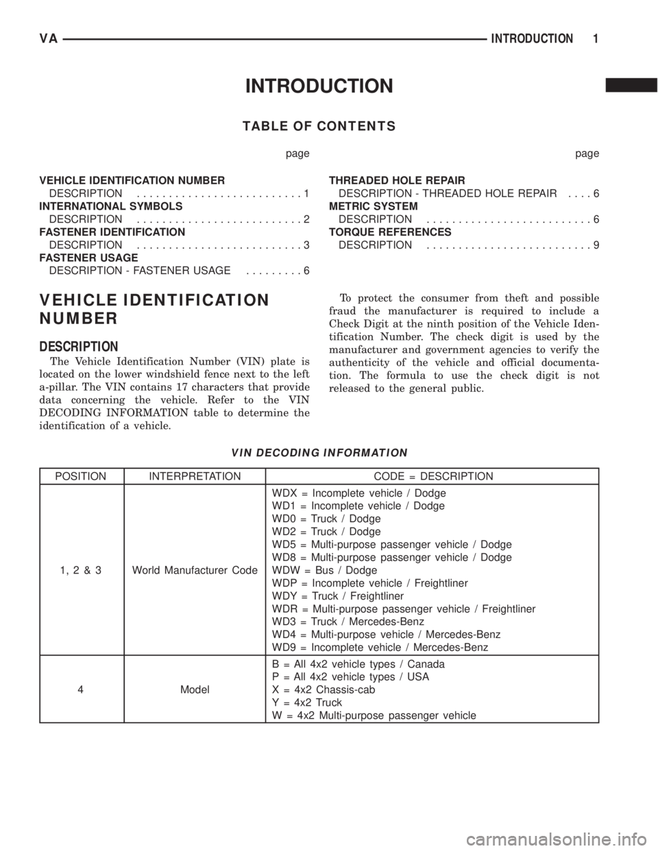
The Vehicle Identification Number (VIN) plate is
located on the lower windshield fence next to the left
a-pillar. The VIN contains 17 characters that provide
data concerning the vehicle. Refer to the VIN
DECODING INFORMATION table to determine the
identification of a vehicle.To protect the consumer from theft and possible
fraud the manufacturer is required to include a
Check Digit at the ninth position of the Vehicle Iden-
tification Number. The check digit is used by the
manufacturer and government agencies to verify the
authenticity of the vehicle and official documenta-
tion. The formula to use the check digit is not
released to the general public.
VIN DECODING INFORMATION
POSITION INTERPRETATION CODE = DESCRIPTION
1,2&3 World Manufacturer CodeWDX = Incomplete vehicle / Dodge
WD1 = Incomplete vehicle / Dodge
WD0 = Truck / Dodge
WD2 = Truck / Dodge
WD5 = Multi-purpose passenger vehicle / Dodge
WD8 = Multi-purpose passenger vehicle / Dodge
WDW = Bus / Dodge
WDP = Incomplete vehicle / Freightliner
WDY = Truck / Freightliner
WDR = Multi-purpose passenger vehicle / Freightliner
WD3 = Truck / Mercedes-Benz
WD4 = Multi-purpose vehicle / Mercedes-Benz
WD9 = Incomplete vehicle / Mercedes-Benz
4 ModelB = All 4x2 vehicle types / Canada
P = All 4x2 vehicle types / USA
X = 4x2 Chassis-cab
Y = 4x2 Truck
W = 4x2 Multi-purpose passenger vehicle
VAINTRODUCTION 1
Page 708 of 2305
FASTENER IDENTIFICATION
DESCRIPTION
The SAE bolt strength grades range from grade 2
to grade 8. The higher the grade number, the greater
the bolt strength. Identification is determined by the
line marks on the top of each bolt head. The actual
bolt strength grade corresponds to the number of line
marks plus 2. The most commonly used metric bolt
strength classes are 9.8 and 10.9. The metric
strength class identification number is imprinted on
the head of the bolt. The higher the class number,
the greater the bolt strength. Some metric nuts are
imprinted with a single-digit strength class on the
nut face. Refer to the Fastener Identification and
Fastener Strength Charts (Fig. 2) and (Fig. 3).
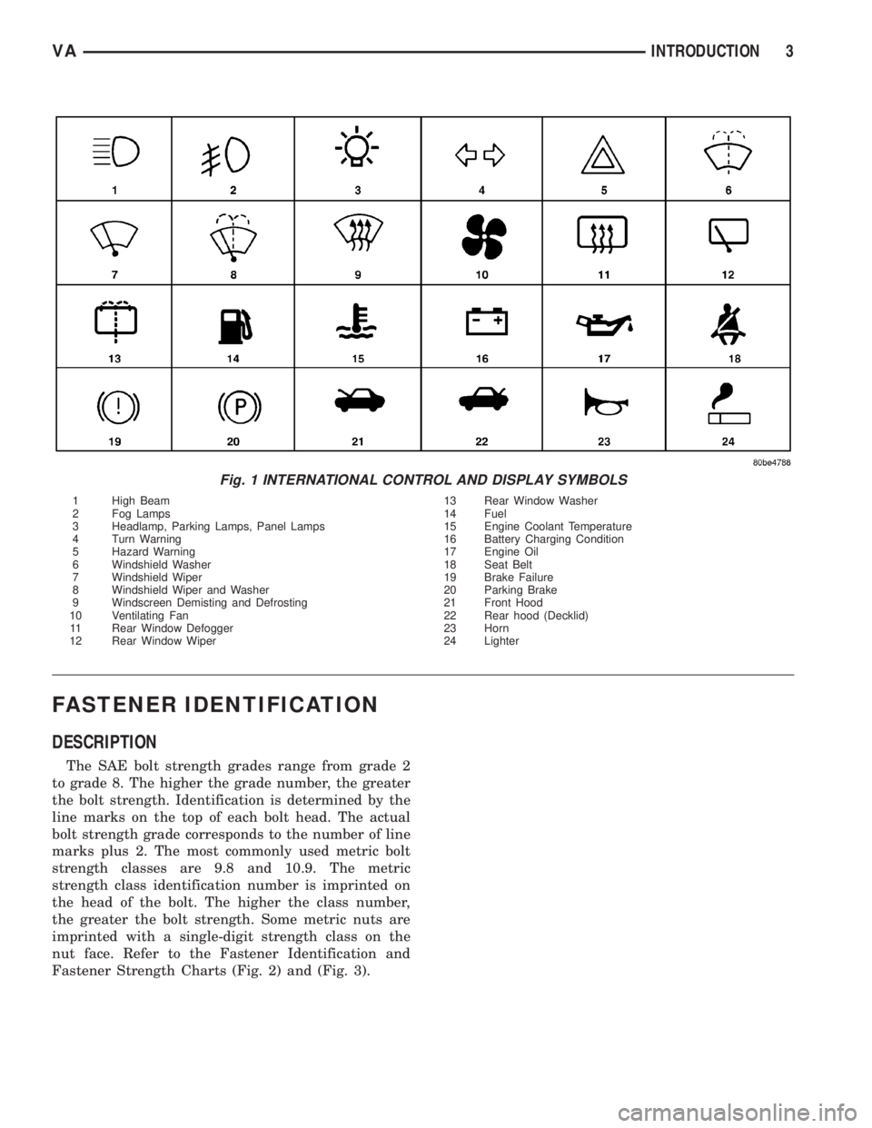
Fig. 1 INTERNATIONAL CONTROL AND DISPLAY SYMBOLS
1 High Beam 13 Rear Window Washer
2 Fog Lamps 14 Fuel
3 Headlamp, Parking Lamps, Panel Lamps 15 Engine Coolant Temperature
4 Turn Warning 16 Battery Charging Condition
5 Hazard Warning 17 Engine Oil
6 Windshield Washer 18 Seat Belt
7 Windshield Wiper 19 Brake Failure
8 Windshield Wiper and Washer 20 Parking Brake
9 Windscreen Demisting and Defrosting 21 Front Hood
10 Ventilating Fan 22 Rear hood (Decklid)
11 Rear Window Defogger 23 Horn
12 Rear Window Wiper 24 Lighter
VAINTRODUCTION 3