2006 LAND ROVER FRELANDER 2 check oil
[x] Cancel search: check oilPage 1770 of 3229
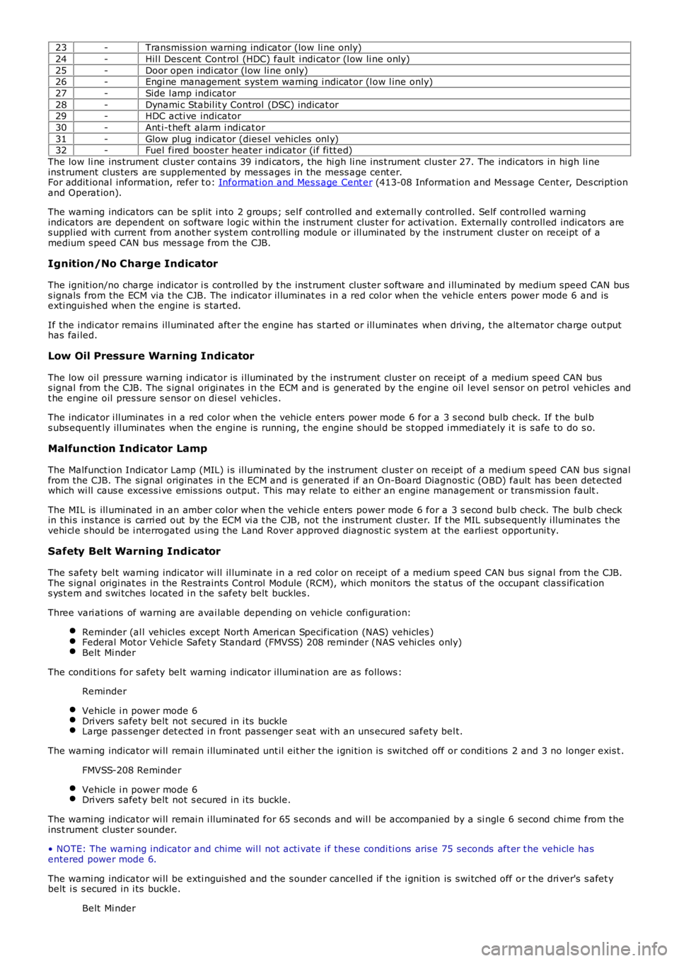
23-Transmis s ion warni ng indi cat or (low li ne only)
24-Hil l Des cent Cont rol (HDC) fault i ndi cat or (l ow li ne only)
25-Door open i ndi cat or (l ow li ne only)26-Engi ne management s yst em warning i ndicat or (l ow l ine only)
27-Side l amp indicat or
28-Dynami c Stabil it y Control (DSC) indicat or29-HDC acti ve indicator
30-Ant i-t heft alarm i ndi cat or
31-Glow pl ug indicat or (dies el vehicles onl y)32-Fuel fired boos ter heater i ndi cat or (i f fi tt ed)
The low li ne ins trument cl ust er cont ains 39 i ndi cat ors , the hi gh li ne ins t rument clus ter 27. The indicators in hi gh li neins t rument clus ters are s upplemented by mess ages in the mess age cent er.For addit ional informat ion, refer t o: Informat ion and Mes s age Cent er (413-08 Informat ion and Mes s age Cent er, Des cript ionand Operat ion).
The warni ng indicators can be s plit i nto 2 groups ; sel f cont roll ed and ext ernall y cont rol led. Self cont rol led warni ngindicat ors are dependent on software l ogi c wit hin t he i ns t rument clus ter for act ivati on. External ly controll ed indicators ares uppl ied wi th current from anot her s yst em cont roll ing module or ill uminat ed by the ins trument cl us t er on receipt of amedium s peed CAN bus mes sage from the CJB.
Ignition/No Charge Indicator
The ignit ion/no charge indicator i s cont rol led by t he ins t rument clus ter s oft ware and i ll uminated by medium speed CAN buss ignals from the ECM via t he CJB. The indicator il lumi nat es i n a red col or when the vehicle ent ers power mode 6 and isexti nguis hed when t he engine i s s tart ed.
If the i ndi cat or remai ns ill uminat ed aft er the engine has s t art ed or ill uminat es when drivi ng, t he alt ernator charge out puthas fai led.
Low Oil Pressure Warning Indicator
The low oil pres s ure warning i ndi cat or is i lluminated by t he i ns t rument clus ter on recei pt of a medium speed CAN buss ignal from t he CJB. The s ignal ori gi nates i n t he ECM and is generat ed by t he engi ne oil l evel s ens or on petrol vehicl es andt he engi ne oil pres s ure s ensor on di esel vehi cles .
The indicat or i ll uminates i n a red color when t he vehi cl e enters power mode 6 for a 3 s econd bulb check. If t he bul bs ubs equent ly ill uminat es when the engine is runni ng, t he engine s houl d be s t opped i mmediat ely i t is s afe to do s o.
Malfunction Indicator Lamp
The Malfunct ion Indicat or Lamp (MIL) i s il lumi nat ed by t he ins trument cl ust er on receipt of a medi um s peed CAN bus s ignalfrom the CJB. The si gnal originat es in t he ECM and i s generated if an On-Board Diagnos ti c (OBD) fault has been det ectedwhich wi ll caus e excess i ve emis s ions output. Thi s may rel ate to ei ther an engine management or trans mi ss i on fault .
The MIL is ill uminat ed in an amber color when t he vehi cl e enters power mode 6 for a 3 s econd bul b check. The bul b checkin thi s ins tance is carri ed out by the ECM vi a t he CJB, not t he ins trument cl ust er. If t he MIL subs equent ly i lluminates t hevehi cl e s houl d be i nterrogated us ing t he Land Rover approved diagnost ic sys tem at the earli es t opport uni ty.
Safety Belt Warning Indicator
The s afety bel t warni ng indicator wi ll il lumi nat e i n a red color on receipt of a medi um s peed CAN bus s ignal from t he CJB.The s ignal origi nat es in the Res traint s Cont rol Module (RCM), which monit ors the s t at us of t he occupant clas s ificati ons ys t em and s wi tches located i n t he s afety bel t buckles .
Three vari ati ons of warning are avai lable depending on vehicle confi gurati on:
Reminder (al l vehicl es except Nort h Ameri can Specificati on (NAS) vehicles )Federal Mot or Vehi cl e Safet y Standard (FMVSS) 208 remi nder (NAS vehi cles only)Belt Mi nder
The condi ti ons for s afety bel t warning indicator il lumi nat ion are as follows :
Reminder
Vehicle i n power mode 6Dri vers s afet y belt not s ecured in i ts buckleLarge pas senger det ect ed i n front pas s enger s eat wit h an uns ecured safety bel t.
The warni ng indicator wi ll remai n i lluminated unt il eit her t he i gni ti on is swi tched off or condi ti ons 2 and 3 no longer exis t .
FMVSS-208 Reminder
Vehicle i n power mode 6Dri vers s afet y belt not s ecured in i ts buckle.
The warni ng indicator wi ll remai n i lluminated for 65 s econds and wil l be accompanied by a si ngl e 6 second chi me from theins t rument clus ter s ounder.
• NOTE: The warni ng indicator and chime wil l not acti vat e i f thes e condi ti ons aris e 75 seconds aft er t he vehicle hasentered power mode 6.
The warni ng indicator wi ll be exti ngui shed and t he s ounder cancell ed if t he i gni ti on is s wi tched off or t he dri ver's s afet ybelt i s s ecured in i ts buckle.
Belt Mi nder
Page 1784 of 3229
Publi s hed: 11-May-2011
Horn - Horn
Diagnosi s and Tes ti ng
Principles of Operation
For a detail ed descripti on of the horn s yst em, refer to the relevant Des cri pt ion and Operati on s ect ion i n t he works hopmanual.REFER to: Horn (413-06 Horn, Descripti on and Operat ion).
Inspection and Verification
CAUTION: Di agnos is by s ubs ti tut ion from a donor vehicle is NO T acceptabl e. Subs ti tut ion of cont rol modules doesnot guarant ee confirmat ion of a faul t, and may als o caus e addit ional fault s i n t he vehi cl e being t est ed and/or t he donorvehi cl e.
1. Verify t he cus t omer concern.1.
2. Vis ually ins pect for obvious s igns of mechani cal or electrical damage.2.
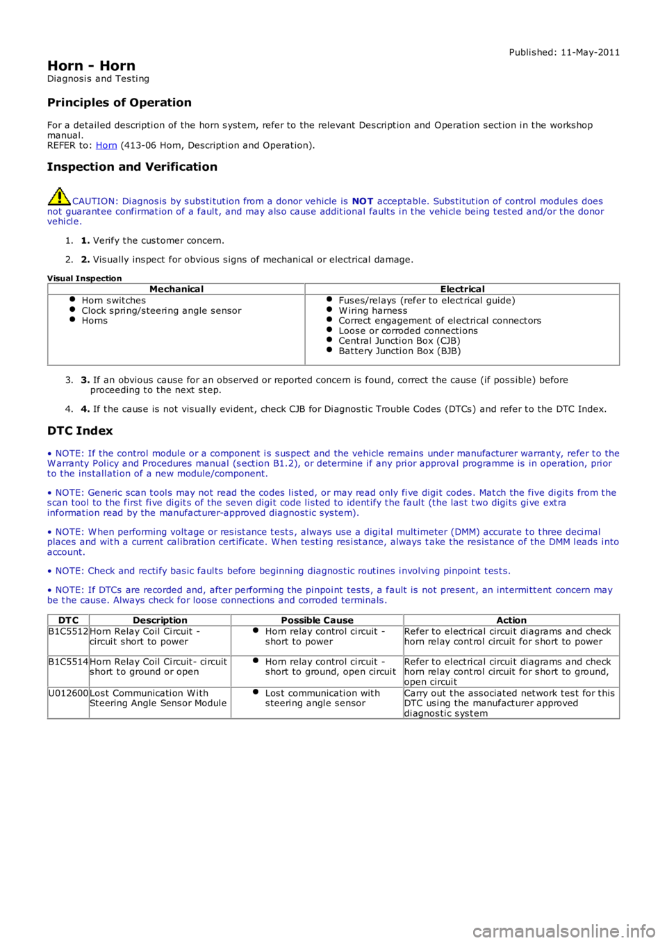
Visual InspectionMechanicalElectrical
Horn s wit chesClock s pri ng/s teeri ng angle s ensorHorns
Fus es/rel ays (refer to elect rical guide)W iring harnes sCorrect engagement of el ect ri cal connect orsLoos e or corroded connecti onsCent ral Juncti on Box (CJB)Bat tery Juncti on Box (BJB)
3. If an obvious cause for an obs erved or report ed concern is found, correct t he caus e (if pos s ible) beforeproceeding t o t he next s t ep.3.
4. If t he caus e is not vis ually evi dent , check CJB for Di agnos ti c Trouble Codes (DTCs ) and refer t o the DTC Index.4.
DTC Index
• NOTE: If the control modul e or a component i s s us pect and the vehicle remains under manufacturer warrant y, refer t o theW arranty Pol icy and Procedures manual (s ect ion B1.2), or determine i f any pri or approval programme is in operat ion, pri ort o the ins tall ati on of a new module/component.
• NOTE: Generic scan t ool s may not read the codes li st ed, or may read only fi ve digit codes . Mat ch the five di git s from t hes can tool to the firs t fi ve di git s of the seven digi t code l is ted to ident ify t he faul t (t he las t t wo digi ts gi ve ext rainformat ion read by the manufact urer-approved diagnost ic s ys tem).
• NOTE: W hen performing volt age or res is t ance t est s , always use a digi tal mult imeter (DMM) accurat e t o t hree deci malplaces and wit h a current cal ibrat ion cert ificate. W hen tes ti ng res i st ance, always take the res is tance of the DMM l eads i ntoaccount.
• NOTE: Check and recti fy bas ic faul ts before beginni ng diagnos t ic rout ines i nvol vi ng pinpoint t es t s.
• NOTE: If DTCs are recorded and, aft er performi ng the pi npoi nt tes ts , a fault is not present , an int ermi tt ent concern maybe t he caus e. Always check for loose connect ions and corroded terminals .
DT CDescriptionPossible CauseActionB1C5512Horn Relay Coil Ci rcuit -circui t s hort to powerHorn relay control ci rcuit -s hort to powerRefer t o el ect ri cal circui t di agrams and checkhorn rel ay cont rol circuit for s hort to power
B1C5514Horn Relay Coil Ci rcuit - ci rcuits hort t o ground or openHorn relay control ci rcuit -s hort to ground, open circui tRefer t o el ect ri cal circui t di agrams and checkhorn rel ay cont rol circuit for s hort to ground,open circui t
U012600Los t Communicati on W i thSt eering Angle Sens or Modul eLos t communicati on wit hs teeri ng angl e s ensorCarry out t he ass ociat ed net work tes t for t hisDTC us i ng the manufact urer approveddi agnos ti c s ys t em
Page 1792 of 3229
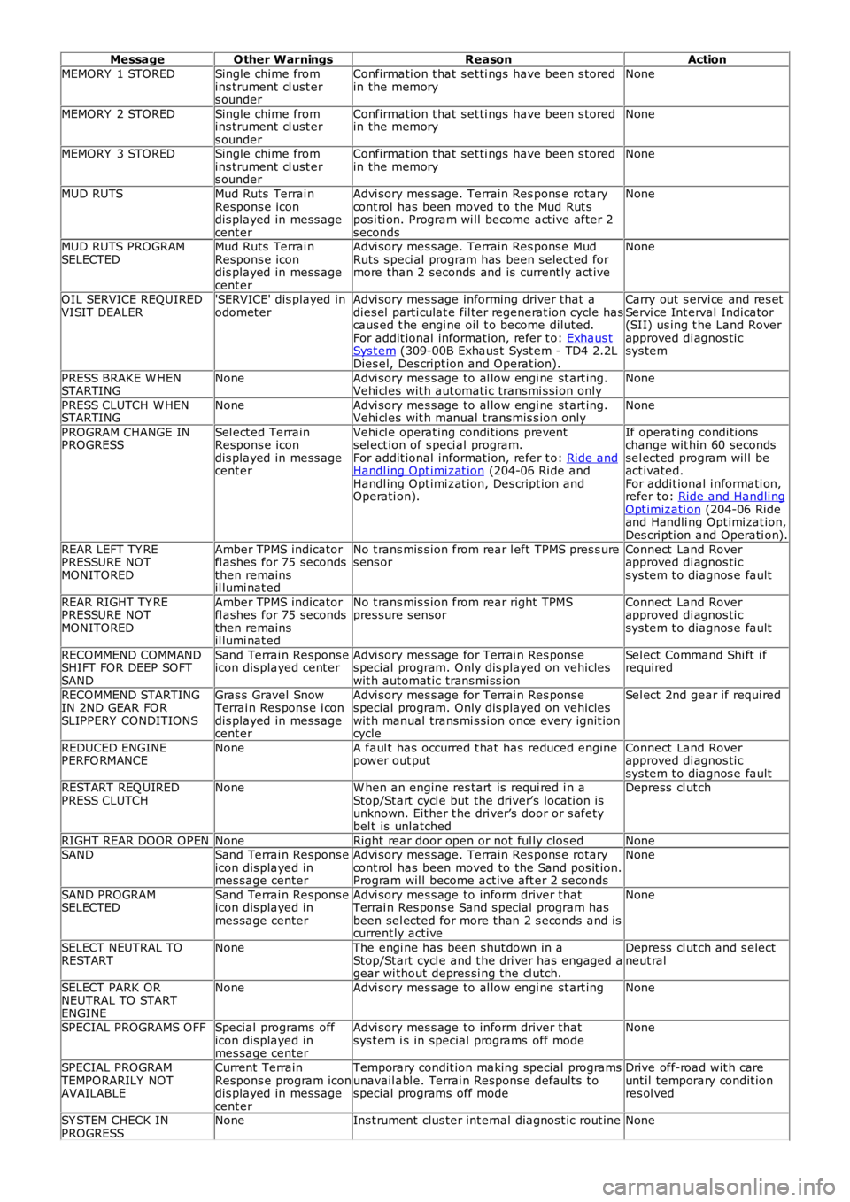
MessageO ther WarningsReasonAction
MEMORY 1 STOREDSingle chime fromins trument cl ust ers ounder
Confirmati on t hat s et ti ngs have been s toredin the memoryNone
MEMORY 2 STOREDSingle chime fromins trument cl ust ers ounder
Confirmati on t hat s et ti ngs have been s toredin the memoryNone
MEMORY 3 STOREDSingle chime fromins trument cl ust ers ounder
Confirmati on t hat s et ti ngs have been s toredin the memoryNone
MUD RUTSMud Ruts Terrai nRespons e icondis played in mess agecent er
Advi sory mes s age. Terrain Res pons e rotarycont rol has been moved to the Mud Rut spos i ti on. Program wi ll become act ive after 2s econds
None
MUD RUTS PROGRAMSELECTEDMud Ruts Terrai nRespons e icondis played in mess agecent er
Advi sory mes s age. Terrain Res pons e MudRuts s peci al program has been s elect ed formore than 2 seconds and is current ly act ive
None
OIL SERVICE REQUIREDVISIT DEALER'SERVICE' dis played inodomet erAdvi sory mes s age informing driver that adies el parti culat e fil ter regenerat ion cycl e hascaus ed t he engi ne oil t o become dilut ed.For addit ional informati on, refer t o: Exhaus tSys t em (309-00B Exhaus t Syst em - TD4 2.2LDies el, Des cript ion and Operat ion).
Carry out s ervi ce and res etServi ce Int erval Indicator(SII) us ing t he Land Roverapproved di agnos ti csys tem
PRESS BRAKE W HENSTARTINGNoneAdvi sory mes s age to al low engi ne st art ing.Vehi cl es wit h aut omati c trans mi s si on onlyNone
PRESS CLUTCH W HENSTARTINGNoneAdvi sory mes s age to al low engi ne st art ing.Vehi cl es wit h manual transmis s ion onlyNone
PROGRAM CHANGE INPROGRESSSel ect ed TerrainRespons e icondis played in mess agecent er
Vehi cl e operat ing condi ti ons prevents el ect ion of s peci al program.For addit ional informati on, refer t o: Ride andHandl ing Opt imi zat ion (204-06 Ri de andHandl ing Opt imi zat ion, Des cript ion andOperati on).
If operat ing condi ti onschange wit hin 60 secondssel ect ed program wil l beact ivated.For addit ional i nformati on,refer t o: Ride and Handli ngOpt imizati on (204-06 Rideand Handli ng Opt imi zat ion,Des cri pti on and Operati on).
REAR LEFT TY REPRESSURE NOTMONITORED
Amber TPMS indicatorfl ashes for 75 secondsthen remainsil lumi nat ed
No t rans mis s ion from rear l eft TPMS pres s ures ens orConnect Land Roverapproved di agnos ti csys tem t o diagnos e fault
REAR RIGHT TY REPRESSURE NOTMONITORED
Amber TPMS indicatorfl ashes for 75 secondsthen remainsil lumi nat ed
No t rans mis s ion from rear right TPMSpres sure s ensorConnect Land Roverapproved di agnos ti csys tem t o diagnos e fault
RECOMMEND COMMANDSHIFT FOR DEEP SOFTSAND
Sand Terrai n Respons eicon dis played cent erAdvi sory mes s age for Terrai n Res pons es pecial program. Only dis played on vehicleswit h automat ic trans mi ss i on
Sel ect Command Shi ft i frequired
RECOMMEND STARTINGIN 2ND GEAR FO RSLIPPERY CONDITIONS
Gras s Gravel SnowTerrai n Res pons e i condis played in mess agecent er
Advi sory mes s age for Terrai n Res pons es pecial program. Only dis played on vehicleswit h manual trans mi s si on once every ignit ioncycle
Sel ect 2nd gear if requi red
REDUCED ENGINEPERFO RMANCENoneA faul t has occurred t hat has reduced enginepower out putConnect Land Roverapproved di agnos ti csys tem t o diagnos e faultRESTART REQ UIREDPRESS CLUTCHNoneW hen an engine res tart is requi red i n aStop/St art cycl e but the driver’s locati on isunknown. Eit her t he dri ver’s door or s afetybel t is unl atched
Depress cl ut ch
RIGHT REAR DOOR OPENNoneRight rear door open or not ful ly clos edNoneSANDSand Terrai n Respons eicon dis played inmes sage center
Advi sory mes s age. Terrain Res pons e rotarycont rol has been moved to the Sand pos it ion.Program wil l become act ive aft er 2 s econds
None
SAND PROGRAMSELECTEDSand Terrai n Respons eicon dis played inmes sage center
Advi sory mes s age to inform driver thatTerrai n Res pons e Sand s pecial program hasbeen sel ect ed for more t han 2 s econds and iscurrent ly acti ve
None
SELECT NEUTRAL TORESTARTNoneThe engi ne has been shut down in aStop/St art cycl e and t he dri ver has engaged agear wi thout depres si ng the cl utch.
Depress cl ut ch and s electneut ral
SELECT PARK ORNEUTRAL TO STARTENGINE
NoneAdvi sory mes s age to al low engi ne st art ingNone
SPECIAL PROGRAMS OFFSpecial programs officon dis played inmes sage center
Advi sory mes s age to inform driver thats ys t em i s in special programs off modeNone
SPECIAL PROGRAMTEMPORARILY NOTAVAILABLE
Current TerrainRespons e program icondis played in mess agecent er
Temporary condit ion making special programsunavail abl e. Terrai n Respons e default s t os pecial programs off mode
Drive off-road wit h careunt il t emporary condit ionres ol ved
SY STEM CHECK INPROGRESSNoneIns t rument clus ter int ernal diagnos t ic rout ineNone
Page 2248 of 3229
Apply acti vat or over t he old sealant on t he wi nds hiel d glas s andall ow t o cure.4.
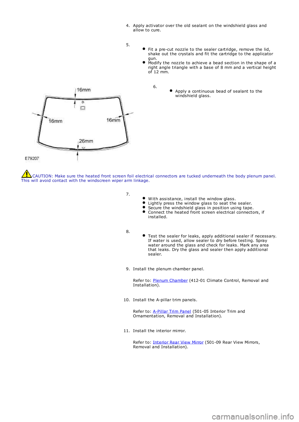
Fit a pre-cut nozzl e t o the sealer cart ri dge, remove the lid,s hake out t he crys tal s and fi t the cartridge t o t he appl icatorgun.Modify t he nozzle to achieve a bead s ecti on in the s hape of aright angl e t ri angle wit h a bas e of 8 mm and a verti cal heightof 12 mm.
5.
Apply a cont inuous bead of s ealant to thewi nds hiel d glas s.
6.
CAUTION: Make s ure the heated front s creen foil electrical connect ors are t ucked underneat h t he body plenum panel.This wi ll avoid contact wit h t he winds creen wi per arm l inkage.
W it h ass i st ance, i ns t all the window glas s .Light ly pres s t he wi ndow glas s to seat t he s eal er.Secure t he winds hield gl ass in pos it ion us ing tape.Connect t he heat ed front s creen electrical connect ors , ifi ns t alled.
7.
Tes t the s ealer for l eaks , appl y addit ional s ealer i f necess ary.If water is used, all ow s eal er to dry before t es t ing. Spraywat er around the gl as s and check for leaks . Mark any areat hat l eaks . Dry the gl ass and sealer t hen appl y addit ionals ealer.
8.
Inst all t he plenum chamber panel.
Refer t o: Plenum Chamber (412-01 Cl imat e Control, Removal andInst all at ion).
9.
Inst all t he A-pi llar t ri m panels .
Refer t o: A-Pil lar Tri m Panel (501-05 Int erior Trim andOrnament ati on, Removal and Ins tal lat ion).
10.
Inst all t he int erior mi rror.
Refer t o: Int erior Rear View Mirror (501-09 Rear Vi ew Mi rrors ,Removal and Ins tall ati on).
11.
Page 2724 of 3229

Contents
4
L
Climate control
AIR VENTS ................................................... 101
MANUAL CLIMATE CONTROL ...................... 102
AUTOMATIC CLIMATE CONTROL ................. 103
HEATED WINDOWS AND MIRRORS ............ 104
AUXILIARY HEATER ..................................... 104
ELECTRIC SUNROOF .................................... 105
Convenience features
SUN VISORS ................................................ 107
CLOCK .......................................................... 107
CIGAR LIGHTER ........................................... 109
ASHTRAY ..................................................... 109
AUXILIARY POWER SOCKETS ..................... 110
CUP HOLDERS ............................................. 111
STORAGE COMPARTMENTS ........................ 112
Starting the engine
GENERAL INFORMATION ............................. 113
STARTING A PETROL ENGINE ..................... 114
STARTING A DIESEL ENGINE ....................... 115
DIESEL PARTICULATE FILTER (DPF) ........... 116
Transmission
MANUAL TRANSMISSION ............................ 118
AUTOMATIC TRANSMISSION ...................... 118
TECHNICAL SPECIFICATIONS ...................... 122
Brakes
PRINCIPLE OF OPERATION .......................... 123
HINTS ON DRIVING WITH ABS .................... 123
PARKING BRAKE .......................................... 124
Parking aid
PRINCIPLE OF OPERATION .......................... 126
USING THE PARKING AID ............................ 127
Driving hints
GENERAL DRIVING POINTS ......................... 128
REDUCED ENGINE PERFORMANCE ............. 128
RUNNING-IN ................................................ 128
ECONOMICAL DRIVING ................................ 129
Cruise control
PRINCIPLE OF OPERATION .......................... 130
USING CRUISE CONTROL ............................ 130
Terrain response
PRINCIPLE OF OPERATION .......................... 132
USING TERRAIN RESPONSE ........................ 132
Hill descent control (HDC)
PRINCIPLE OF OPERATION .......................... 136
USING HDC ................................................... 137
Traction control
USING TRACTION CONTROL ........................ 139
Stability control
PRINCIPLE OF OPERATION .......................... 140
USING STABILITY CONTROL ........................ 141
Fuel and refuelling
SAFETY PRECAUTIONS................................. 142
FUEL QUALITY .............................................. 142
RUNNING OUT OF FUEL................................ 144
FUEL CUT-OFF............................................... 144
FUEL FILLER FLAP ........................................ 144
REFUELLING ................................................. 145
TECHNICAL SPECIFICATIONS ....................... 146
Load carrying
GENERAL INFORMATION.............................. 147
LUGGAGE ANCHOR POINTS ......................... 148
LUGGAGE COVERS ....................................... 149
Towing
TOWING A TRAILER...................................... 150
LEVELLING.................................................... 151
ESSENTIAL TOWING CHECKS ...................... 151
RECOMMENDED TOWING WEIGHTS ............ 152
TOW BAR ...................................................... 153
Vehicle care
CLEANING THE ALLOY WHEELS................... 154
CLEANING THE EXTERIOR ............................ 154
CLEANING THE INTERIOR ............................ 155
REPAIRING MINOR PAINT DAMAGE ............ 156
Maintenance
GENERAL INFORMATION.............................. 157
OPENING AND CLOSING THE BONNET......... 160
ENGINE COMPARTMENT OVERVIEW ........... 161
ENGINE OIL CHECK....................................... 162
Page 2741 of 3229
21
Quick start
R
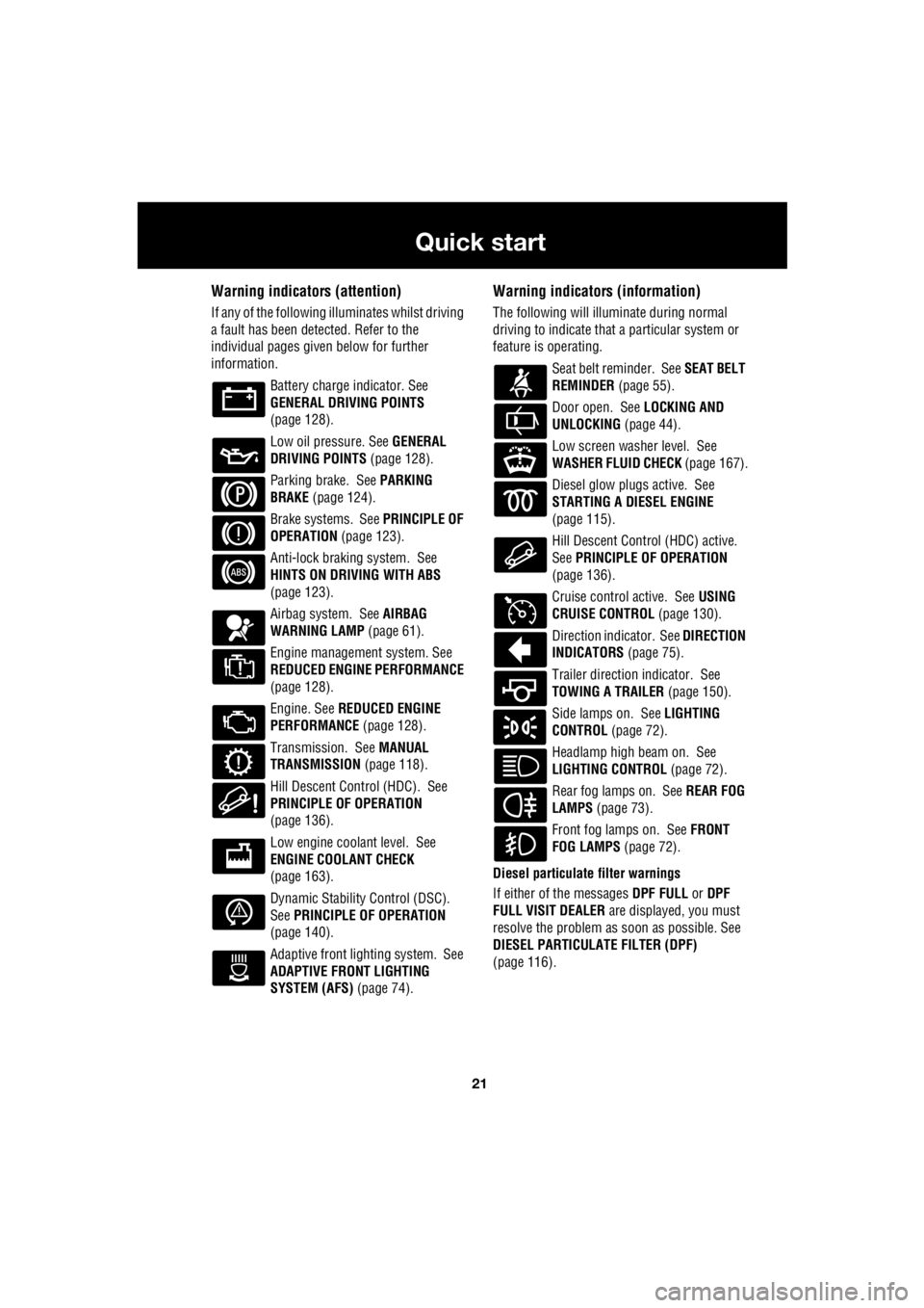
Warning indicators (attention)
If any of the following illuminates whilst driving
a fault has been detected. Refer to the
individual pages give n below for further
information.
Battery charge indicator. See
GENERAL DRIVING POINTS
(page 128).
Low oil pressure. See GENERAL
DRIVING POINTS (page 128).
Parking brake. See PARKING
BRAKE (page 124).
Brake systems. See PRINCIPLE OF
OPERATION (page 123).
Anti-lock braking system. See
HINTS ON DRIVING WITH ABS
(page 123).
Airbag system. See AIRBAG
WARNING LAMP (page 61).
Engine management system. See
REDUCED ENGINE PERFORMANCE
(page 128).
Engine. See REDUCED ENGINE
PERFORMANCE (page 128).
Transmission. See MANUAL
TRANSMISSION (page 118).
Hill Descent Control (HDC). See
PRINCIPLE OF OPERATION
(page 136).
Low engine coolant level. See
ENGINE COOLANT CHECK
(page 163).
Dynamic Stability Control (DSC).
See PRINCIPLE OF OPERATION
(page 140).
Adaptive front lighting system. See
ADAPTIVE FRONT LIGHTING
SYSTEM (AFS) (page 74).
Warning indicators (information)
The following will illuminate during normal
driving to indicate that a particular system or
feature is operating.
Seat belt reminder. See SEAT BELT
REMINDER (page 55).
Door open. See LOCKING AND
UNLOCKING (page 44).
Low screen washer level. See
WASHER FLUID CHECK (page 167).
Diesel glow plugs active. See
STARTING A DIESEL ENGINE
(page 115).
Hill Descent Control (HDC) active.
See PRINCIPLE OF OPERATION
(page 136).
Cruise control active. See USING
CRUISE CONTROL (page 130).
Direction indicator. See DIRECTION
INDICATORS (page 75).
Trailer direction indicator. See
TOWING A TRAILER (page 150).
Side lamps on. See LIGHTING
CONTROL (page 72).
Headlamp high beam on. See
LIGHTING CONTROL (page 72).
Rear fog lamps on. See REAR FOG
LAMPS (page 73).
Front fog lamps on. See FRONT
FOG LAMPS (page 72).
Diesel particulate filter warnings
If either of the messages DPF FULL or DPF
FULL VISIT DEALER are displayed, you must
resolve the problem as soon as possible. See
DIESEL PARTICULATE FILTER (DPF)
(page 116).
Page 2754 of 3229
34
Filling station information
L
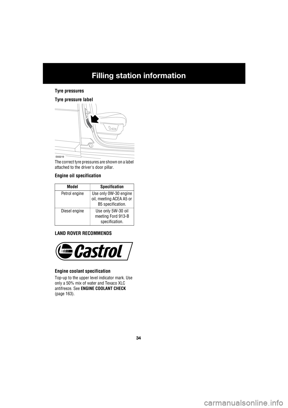
Tyre pressures
Tyre pressure label
The correct tyre pressures are shown on a label
attached to the dr iver's door pillar.
Engine oil specification
LAND ROVER RECOMMENDS
Engine coolant specification
Top-up to the upper level indicator mark. Use
only a 50% mix of water and Texaco XLC
antifreeze. See ENGINE COOLANT CHECK
(page 163). Model Specification
Petrol engine Use only 0W-30 engine oil, meeting ACEA A5 or
B5 specification.
Diesel engine Use only 5W-30 oil meeting Ford 913-B
specification.
E83219
Page 2848 of 3229
Driving hints
128
L
Driving hintsGENERAL DRIVING POINTS
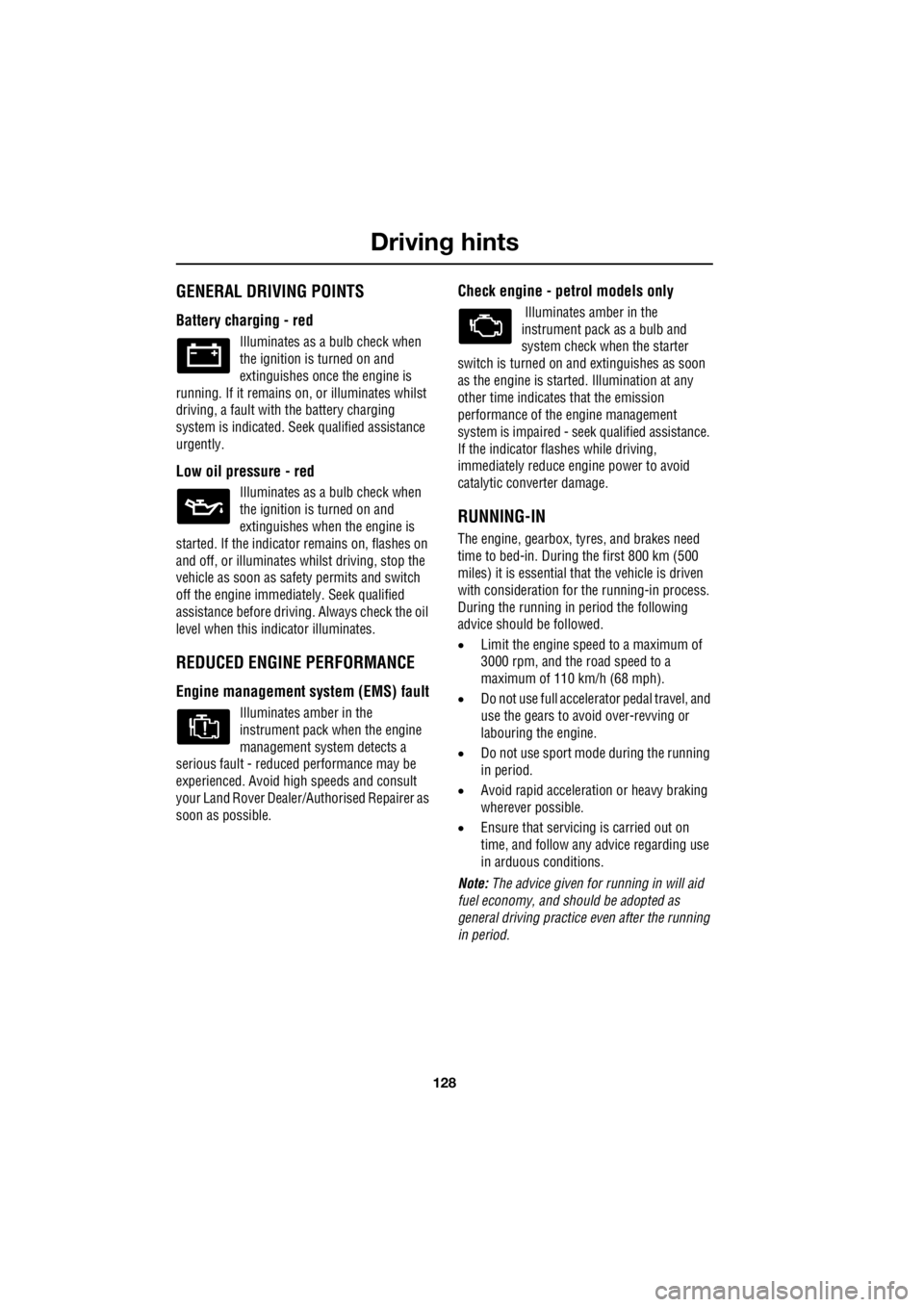
Battery charging - red
Illuminates as a bulb check when
the ignition is turned on and
extinguishes once the engine is
running. If it remains on, or illuminates whilst
driving, a fault with the battery charging
system is indicated. Seek qualified assistance
urgently.
Low oil pressure - red
Illuminates as a bulb check when
the ignition is turned on and
extinguishes when the engine is
started. If the indicator remains on, flashes on
and off, or illuminates whilst driving, stop the
vehicle as soon as safety permits and switch
off the engine immediat ely. Seek qualified
assistance before driving. Always check the oil
level when this indicator illuminates.
REDUCED ENGINE PERFORMANCE
Engine management syst em (EMS) fault
Illuminates amber in the
instrument pack when the engine
management system detects a
serious fault - reduce d performance may be
experienced. Avoid high speeds and consult
your Land Rover Dealer/A uthorised Repairer as
soon as possible.
Check engine - petrol models only
Illuminates amber in the
instrument pack as a bulb and
system check when the starter
switch is turned on and extinguishes as soon
as the engine is starte d. Illumination at any
other time indicates that the emission
performance of the engine management
system is impaired - seek qualified assistance.
If the indicator flashes while driving,
immediately reduce e ngine power to avoid
catalytic converter damage.
RUNNING-IN
The engine, gearbox, tyre s, and brakes need
time to bed-in. During the first 800 km (500
miles) it is essential th at the vehicle is driven
with consideration for the running-in process.
During the running in period the following
advice should be followed.
• Limit the engine speed to a maximum of
3000 rpm, and the road speed to a
maximum of 110 km/h (68 mph).
• Do not use full accelerator pedal travel, and
use the gears to avoid over-revving or
labouring the engine.
• Do not use sport mode during the running
in period.
• Avoid rapid accelerati on or heavy braking
wherever possible.
• Ensure that servicing is carried out on
time, and follow any advice regarding use
in arduous conditions.
Note: The advice given for running in will aid
fuel economy, and s hould be adopted as
general driving practice even after the running
in period.