Page 2354 of 3229

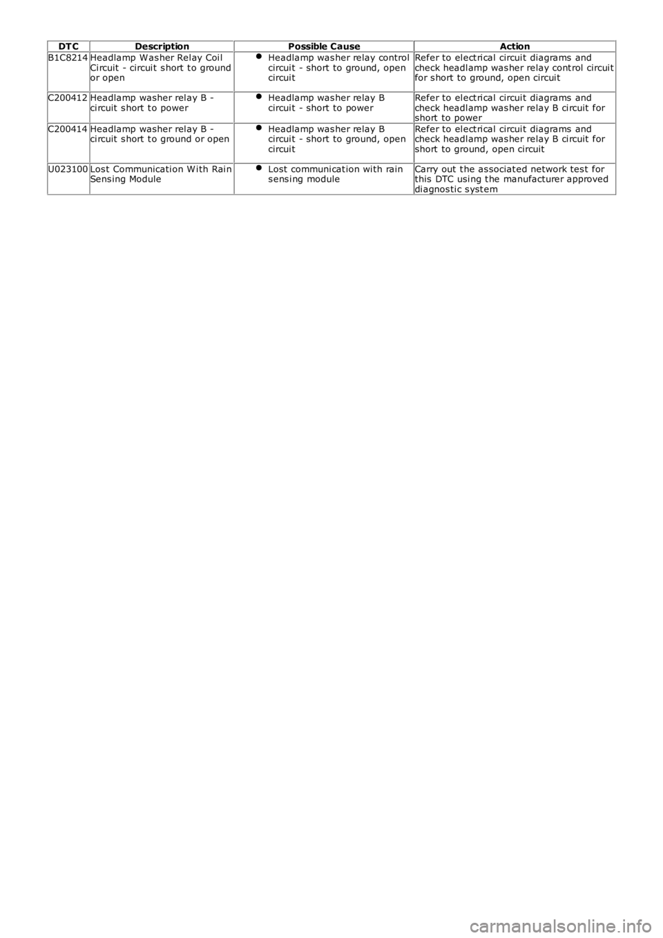
DT C
Description Possible Cause Action
B1C8214 Headlamp W as her Rel ay Coi l
Ci rcuit - circui t s hort t o ground
or open Headlamp was her relay control
circui t - short to ground, open
circui t Refer to el ect ri cal circui t diagrams and
check headl amp was her relay cont rol circui t
for s hort to ground, open circui t
C200412 Headlamp washer rel ay B -
ci rcuit s hort t o power Headlamp was her relay B
circui t - short to power Refer to el ect ri cal circui t diagrams and
check headl amp was her relay B ci rcuit for
short to power
C200414 Headlamp washer rel ay B -
ci rcuit s hort t o ground or open Headlamp was her relay B
circui t - short to ground, open
circui t Refer to el ect ri cal circui t diagrams and
check headl amp was her relay B ci rcuit for
short to ground, open circuit
U023100 Los t Communicati on W i th Rai n
Sens ing Module Lost communi cat ion wi th rain
s ens i ng module Carry out t he as sociat ed network tes t for
this DTC usi ng t he manufacturer approved
di agnos ti c s yst em
Page 2358 of 3229
Publi s hed: 11-May-2011
Wipers and Washers - Headlamp Washer Jet
Removal and Inst all ati on
Removal
1. W ARNING: Do not work on or under a vehi cle s upported onl y
by a jack. Al ways support t he vehi cl e on s afet y s tands .
Rais e and s upport t he vehi cl e.
1.
Remove t he front wheel s and ti res .
Refer t o: W heel and Ti re (204-04 W heel s and Tires, Removal and
Inst all at ion).
2.
Remove t he front bumper cover.
Refer t o: Front Bumper Cover (501-19 Bumpers, Removal and
Inst all at ion).
3. 4.
Installation To i nst all , revers e t he removal procedure.
1.
Page 2363 of 3229
Publi s hed: 11-May-2011
Wipers and Washers - Headlamp Washer Pump
Removal and Inst all ati on
Removal
1. W ARNING: Do not work on or under a vehi cle s upported onl y
by a jack. Al ways support t he vehi cl e on s afet y s tands .
Rais e and s upport t he vehi cl e.
1.
Remove t he RH fender s plas h s hield.
Refer t o: Fender Spl ash Shi eld (501-02 Front End Body Panel s ,
Removal and Ins tall ati on).
2.
Drai n t he was her reservoi r fl ui d.
3. 4.
NOTE: Do not dis ass embl e further if t he component
i s removed for acces s onl y.
Remove t he headl amp was her pump.
4.
Installation To i nst all , revers e t he removal procedure.
1.
Page 2510 of 3229

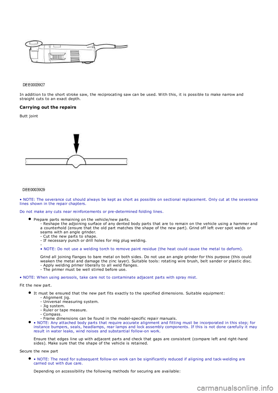
In addi ti on t o the short st roke s aw, t he reciprocati ng s aw can be us ed. W it h t his , it i s poss i bl e t o make narrow ands traight cut s t o an exact depth.
Carrying out the repairs
Butt joint
• NOTE: The s everance cut s houl d always be kept as s hort as poss i bl e on s ecti onal repl acement. Onl y cut at t he s everanceli nes shown in t he repair chapters.
Do not make any cuts near rei nforcements or pre-determined folding lines .
Prepare parts remaini ng on t he vehi cl e/new parts .- Res hape t he adjoi ni ng s urface of any dented body part s t hat are t o remai n on t he vehicle us ing a hammer anda count erhold (ens ure t hat the ol d part mat ches the s hape of the new part ). Grind off left over s pot wel ds ors eams wit h an angle grinder.- Cut the new part s to s hape.- If neces sary punch or drill holes for mig plug wel di ng.-• NOTE: Do not us e a wel ding t orch t o remove pai nt res idue (the heat coul d caus e t he met al to deform).
Gri nd all joining flanges to bare met al on both s i des . Do not us e an angle grinder for t hi s purpos e (this couldweaken the met al and damage the zi nc layer). Sui table tools : rot ati ng wi re brush, belt s ander or plas t ic dis c.- Apply wel di ng pri mer li berall y to all weld flanges .- The pri mer mus t be well s t irred before us e.
• NOTE: W hen us ing aerosol s, t ake care not t o cont aminat e adjacent part s wi th spray mi st .
Fit t he new part .
It must be ens ured that t he new part fit s exact ly t o t he s pecified di mensi ons. Suit able equipment :- Ali gnment jig.- Univers al meas uring s ys tem.- Jig s ys tem.- Ruler or tape meas ure.- Compass .- Frame dimens ions can be found i n t he model-specific repai r manual s.• NOTE: Any att ached body part s t hat require accurat e ali gnment and fit t ing mus t be i ncorporat ed i n t hi s s tep; forins t ance bumpers , s eal s , headlamps , rear l amps and lock as sembl y components . If thi s is not done careful ly i t mayres ult i n wat er l eaks , wi nd noi s es and subs tant ial fol low-on work.
Ensure t hat edges li ne up wi th adjacent part s and check t hat gaps are cons is t ent (compare l eft and right-hands ides ). Make s ure that the shape of t he vehi cl e is ret ai ned.
Secure t he new part
• NOTE: The need for s ubsequent foll ow-on work can be s ignificantl y reduced if ali gni ng and t ack-wel ding arecarri ed out wit h due care.
Dependi ng on acces si bili ty the foll owing met hods for s ecuri ng are avai lable:
Page 2529 of 3229
ItemFromT oDimension
ADamper mount ing rear hol eRoof corner poi nt1597.25BRH Fender rear fixi ng hol eLH Fender rear fi xing hole1583.9
CRH Damper mounti ng rear holeLH Damper mount ing rear hol e1136
DRH Fender middle fixi ng hol eLH Fender middle fi xi ng hole1558.9ERH Headlamp top i nboard fi xing holeLH Headl amp t op inboard fixing hol e1061.5
Page 2537 of 3229
SectionDescriptionGapProfile
A-AHood t o bumper cover gap5.0 +2.0 -0.0N/AB-BFront bumper cover t o headl amp gap5.0 ±2.5 (maximum taper 2.0)N/A
C-CHood t o headlamp gap5.0 +2.0 -0.0N/A
D-DHeadlamp to bumper cover4.0 ±2.0N/AE-EFender to headlamp3.0 ±1.01.0 ±1.5
F-FFender to bumper cover2.0 +1.0 -0.01.5 ±1.0
G-G5.0 ±1.7N/A
Page 2723 of 3229

Contents
3
R
Quick start
QUICK START ................................................... 7
Filling station information
FILLING STATION INFORMATION................... 33
Introduction
SYMBOLS GLOSSARY .................................... 35
LABEL LOCATIONS ......................................... 35
HEALTH AND SAFETY ..................................... 36
DATA RECORDING.......................................... 37
DISABILITY MODIFICATIONS ......................... 37
PARTS AND ACCESSORIES ............................ 37
Keys and remote controls
USING THE KEY .............................................. 40
GENERAL INFORMATION ON RADIO
FREQUENCIES ................................................ 40
USING THE REMOTE CONTROL ..................... 41
Locks
LOCKING AND UNLOCKING ............................ 44
Alarm
ARMING THE ALARM ..................................... 45
DISARMING THE ALARM ............................... 46
Seats
SITTING IN THE CORRECT POSITION ............ 47
MANUAL SEATS ............................................. 48
ELECTRIC SEATS ............................................ 49
HEAD RESTRAINTS ........................................ 51
REAR SEATS................................................... 51
HEATED SEATS............................................... 53
Seat belts
PRINCIPLE OF OPERATION ............................ 54
SEAT BELT REMINDER ................................... 55
FASTENING THE SEAT BELTS ........................ 56
SEAT BELT HEIGHT ADJUSTMENT................. 56
USING SEAT BELTS DURI NG PREGNANCY .... 57
Supplementary restraints system
PRINCIPLE OF OPERATION ............................ 58
AIRBAG WARNING LAMP ............................... 61
DISABLING THE PASSENGER AIRBAG ........... 62
AIRBAG SERVICE INFORMATION ................... 63
Child safety
CHILD SEATS ................................................. 64
BOOSTER CUSHIONS ..................................... 66
ISOFIX ANCHOR POINTS................................ 67
CHILD SAFETY LOCKS ................................... 69
Steering wheel
ADJUSTING THE STEERING WHEEL .............. 70
AUDIO CONTROL ........................................... 70
Lighting
LIGHTING CONTROL ...................................... 72
FRONT FOG LAMPS........................................ 72
REAR FOG LAMPS.......................................... 73
ADJUSTING THE HEADLAMPS....................... 73
HEADLAMP LEVELLING ................................. 73
HAZARD WARNING FLASHERS...................... 74
ADAPTIVE FRONT LIGHTING SYSTEM (AFS) . 74
DIRECTION INDICATORS ............................... 75
INTERIOR LAMPS .......................................... 76
APPROACH LAMPS ........................................ 76
CHANGING A BULB ........................................ 77
BULB SPECIFICATION CHART ........................ 86
Wipers and washers
WINDSCREEN WIPERS .................................. 87
RAIN SENSOR ................................................ 87
WINDSCREEN WASHERS............................... 88
HEADLAMP WASHERS................................... 88
REAR WINDOW WIPER AND WASHERS ........ 89
ADJUSTING THE WINDSCREEN WASHER JETS .
89
CHECKING THE WIPER BLADES .................... 90
CHANGING THE WIPER BLADES.................... 90
Windows and mirrors
ELECTRIC WINDOWS ..................................... 93
EXTERIOR MIRRORS ..................................... 94
ELECTRIC EXTERIOR MIRRORS .................... 95
INTERIOR MIRROR ........................................ 96
Instruments
INSTRUMENT PANEL OVERVIEW .................. 97
Information displays
TRIP COMPUTER ........................................... 99
INFORMATION MESSAGES ............................ 99
Page 2727 of 3229

7
Quick start
R
Quick startQUICK START
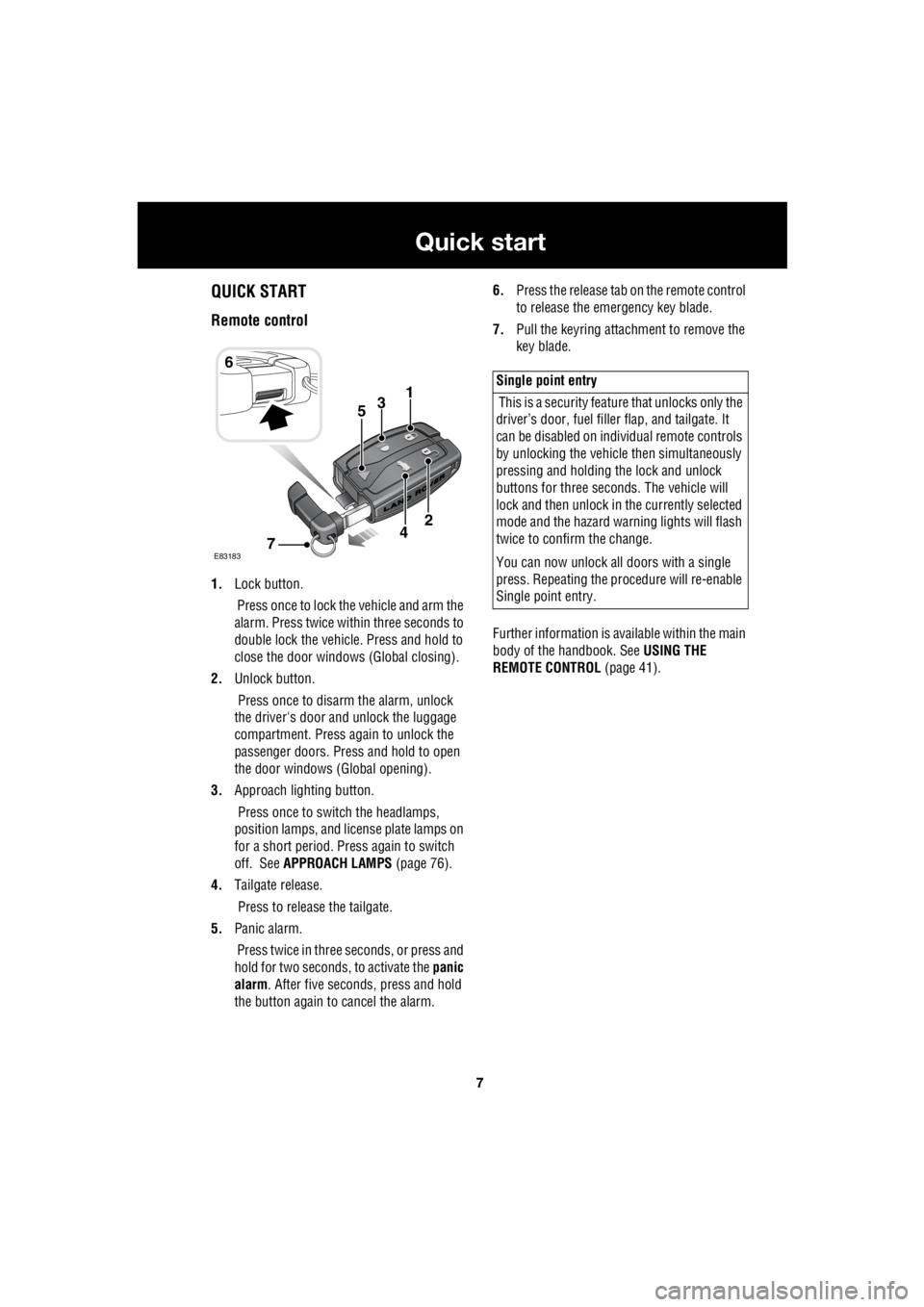
Remote control
1. Lock button.
Press once to lock the vehicle and arm the
alarm. Press twice within three seconds to
double lock the vehicle. Press and hold to
close the door windows (Global closing).
2. Unlock button.
Press once to disarm the alarm, unlock
the driver's door and unlock the luggage
compartment. Press again to unlock the
passenger doors. Press and hold to open
the door windows (Global opening).
3. Approach lighting button.
Press once to switch the headlamps,
position lamps, and license plate lamps on
for a short period. Press again to switch
off. See APPROACH LAMPS (page 76).
4. Tailgate release.
Press to release the tailgate.
5. Panic alarm.
Press twice in three seconds, or press and
hold for two seconds, to activate the panic
alarm . After five seconds, press and hold
the button again to cancel the alarm. 6.
Press the release tab on the remote control
to release the emergency key blade.
7. Pull the keyring attachment to remove the
key blade.
Further information is available within the main
body of the handbook. See USING THE
REMOTE CONTROL (page 41).
6
31
E83183
2
74
5
Single point entry
This is a security feature that unlocks only the
driver’s door, fuel fille r flap, and tailgate. It
can be disabled on indi vidual remote controls
by unlocking the vehicle then simultaneously
pressing and holding th e lock and unlock
buttons for three sec onds. The vehicle will
lock and then unlock in the currently selected
mode and the hazard wa rning lights will flash
twice to confirm the change.
You can now unlock all doors with a single
press. Repeating the pr ocedure will re-enable
Single point entry.