2006 LAND ROVER FRELANDER 2 headlamp
[x] Cancel search: headlampPage 2054 of 3229
it recei ves an alarm s ignal from t he CJB or the t il t s ens ort he power s upply or t he LIN bus link t o t he CJB is dis rupted.
The t ilt s ens or meas ures the l ongi tudinal and lat eral angl e of the vehicl e over a range of ±16 degrees from the hori zont al.W hen t he acti ve ant i-t heft s ys t em i s armed in volumet ri c mode, the t il t s ens or s tores the current vehi cl e angl es in it smemory and monit ors t he t il t sens or readings. If t he vehi cl e angle changes i n eit her di recti on by more t han the al armli mit , t he ti lt s ensor acti vat es t he s ounder.
If the al arm sys tem is act ive and t he batt ery or t he batt ery backed sounder is di sconnect ed, t he s ounder wil l operatewit hout the vi sual indicati on of the turn s ignal i ndicat ors fl as hing.
Global Open/Close
The global open/cl os e feature all ows the us er t o ful ly rais e/l ower t he wi ndows wit h a s ingle pres s of a remote hands etbutt on. The but ton must be press ed and held for more t han 2 s econds. Ei ther or bot h gl obal open/clos e functi ons can bedis abled us ing a Land Rover approved di agnos ti c s yst em.
• NOTE: Remote global cl os e i s not avai lable in cert ain markets , Nort h American Speci ficat ion (NAS) for exampl e.
Single Point Entry
The s ingle poi nt ent ry feature only unlocks the driver's door and the l iftgate, al l ot her doors remai n locked. A si ngle pres sof the unl ock but ton on the remote hands et wil l unl ock only the driver's door and t he li ft gate, a s econd pres s is requi red tounlock the remaini ng doors .
If the vehicle is double l ocked, the firs t pres s of the unlock butt on on t he remote hands et unl ocks t he dri ver's door and theli ft gate. The remai ning doors revert t o the si ngl e l ocked s tat e and can t herefore be unlocked us ing the i nteri or doorhandl es, t he remot e handset unlock butt on or t he unl ock swi tch on the i nst rument panel swi tchpack.
Changi ng from central locki ng to si ngle point ent ry can be carried out by pres s ing the l ock and unlock butt ons on t heremot e handset s imult aneousl y. The turn s ignal i ndicat ors wil l flas h t o confirm that t he functi on change has beenperformed.
Drive Away Locking
The dri ve away door l ocking feature locks the doors and the lift gat e i f they are unlocked when t he vehi cle reaches a cert ains peed.
On vehicles wi th aut omat ic t rans mis s ion, wit h al l t he doors , li ft gate and hood clos ed and t he gear s elector not in 'P' Parkor 'N' Neutral pos it ion, if t he CJB detects , via a high s peed CAN mes s age from t he Ant i-lock Brake Syst em (ABS) module,t hat t he vehi cle s peed is more t han 7 km/h (5 mph), the doors wil l aut omati cal ly l ock.
On vehicles wi th manual t rans mis s ion, wi th al l the doors , l ift gate and hood cl os ed, if t he CJB detects , via a high s peedCAN mes s age from t he ABS modul e, t hat the vehicle speed i s more than 7 km/h (5 mph), t he doors wi ll automat ically lock.
Remote Handset Additional Features
The remot e handset has convenience butt ons in addit ion to the l ock and unl ock but tons .
Pani c Alarm
The pani c alarm feature allows the us er to act ivate the vehicle alarm s yst em us ing the remote hands et. The 'panic but ton',identi fi ed by a t ri angl e s ymbol, can be pres s ed 3 t imes wit hi n 3 s econds or pres s ed and held for more than 3 seconds toact ivat e t he pani c alarm.
Global Open/Close
A gl obal open and clos e feat ure can be operat ed from t he remote hands et . This feature allows the vehicle windows t o beopened/cl os ed by a s ingle press of t he l ock or unlock butt on. The but ton must be press ed and held for more t han 2s econds t o act ivat e the gl obal open/clos e feat ure. The global open/cl ose feature i s not avail abl e i n all market s .
Liftgate Release
A l iftgat e rel eas e but ton can pres s ed t o unlock and rel eas e t he li ft gate latch only. This will operat e wi th the vehicle lockedand alarmed or unl ocked. If t he vehicle i s locked and alarmed, when t he l iftgate releas e butt on i s pres s ed, t he li ft gate canbe opened wit hout t ri ggering t he alarm s ys tem. W hen the liftgat e is subs equent ly clos ed, the al arm wil l be re-act ivated.
Headlamp Convenience
A headlamp conveni ence but ton can be press ed t o operat e the headlamps to as s is t departure or approach to the vehicle. As ingle press of the but ton wi ll operat e the headlamps for approxi mat el y 25 s econds , aft er whi ch ti me t hey wil lautomat ically turn off. A s econd press of t he butt on wi ll t urn off the headlamps i f the 25 second period has not beenreached. Pres s ing the s t op/s tart but ton wit hin t he 25 s econd period wi ll als o t urn off t he headlamp convenience feature.
Convenience mode
W hen t he vehicle i s unlocked us i ng the unl ock but ton on t he remote hands et , t he vehicl e's electrical s ys t em i ni ti atesconvenience mode. The foll owing s yst ems become acti ve:
Memory - s eat adjus t ment and mirror pos it ionInt eri or and ext erior l ighti ngAudio s ys temIns t rument clus ter mes s age cent reHornCigar li ght er/power socket .
Page 2067 of 3229
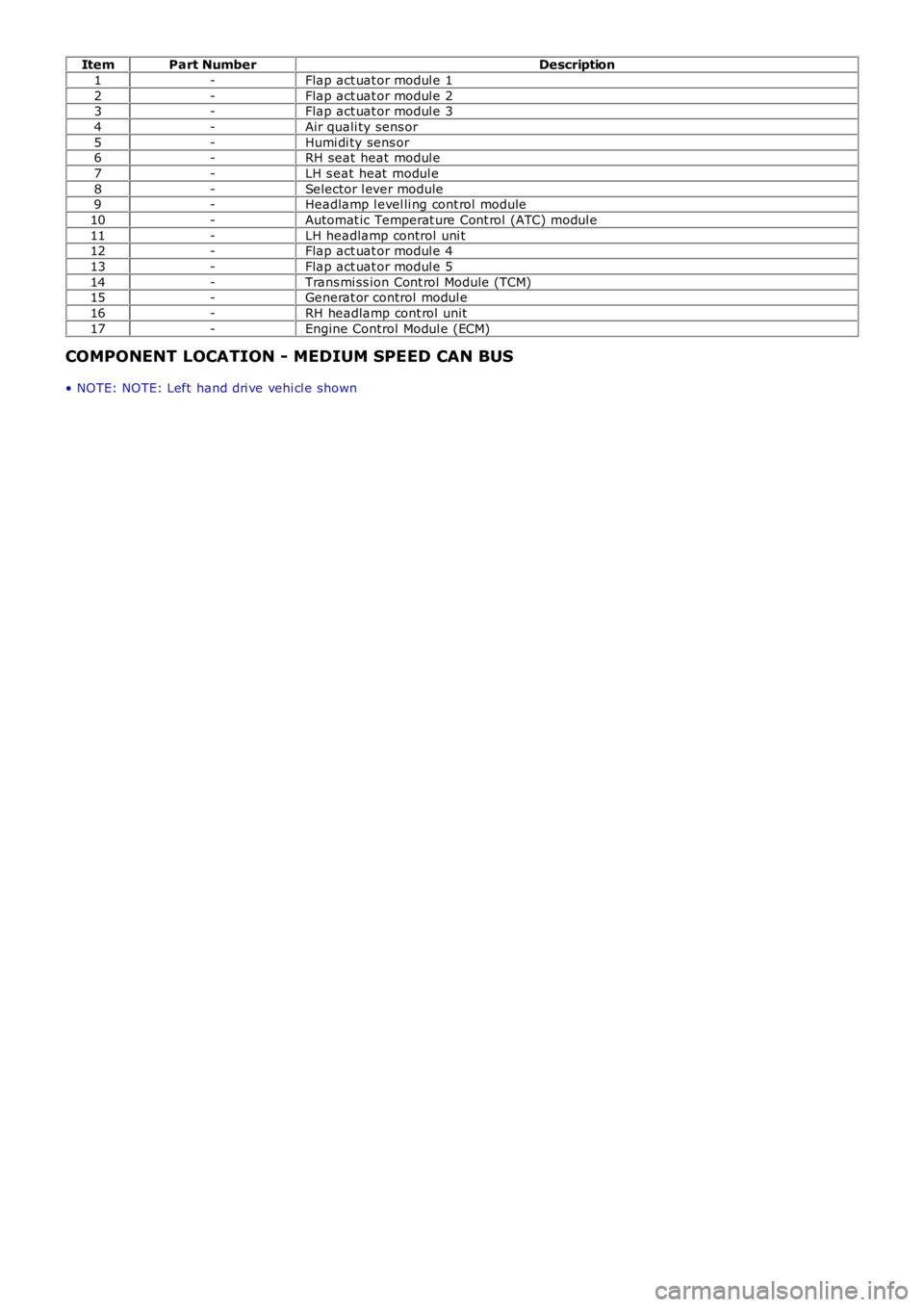
ItemPart NumberDescription
1-Flap act uat or modul e 1
2-Flap act uat or modul e 23-Flap act uat or modul e 3
4-Air quali ty sens or
5-Humi di ty sens or6-RH seat heat modul e
7-LH s eat heat modul e
8-Selector l ever module9-Headlamp l evel li ng cont rol module
10-Automat ic Temperat ure Cont rol (ATC) modul e
11-LH headlamp control uni t12-Flap act uat or modul e 4
13-Flap act uat or modul e 5
14-Trans mi ss ion Cont rol Module (TCM)15-Generat or control modul e
16-RH headlamp cont rol unit
17-Engine Control Modul e (ECM)
COMPONENT LOCATION - MEDIUM SPEED CAN BUS
• NOTE: NOTE: Left hand dri ve vehi cl e s hown
Page 2072 of 3229
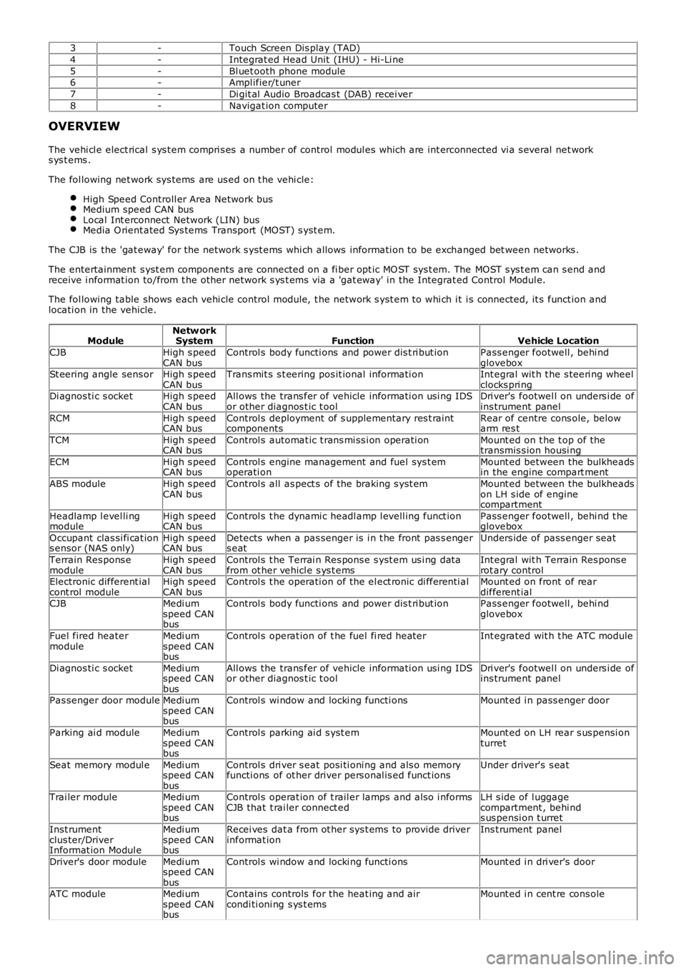
3-Touch Screen Dis play (TAD)
4-Integrat ed Head Unit (IHU) - Hi-Li ne
5-Bl uet ooth phone module6-Ampl ifier/t uner
7-Di git al Audio Broadcas t (DAB) recei ver
8-Navigat ion computer
OVERVIEW
The vehi cl e elect rical s ys t em compri s es a number of control modul es which are int erconnected vi a s everal net works ys t ems .
The fol lowing net work sys tems are us ed on t he vehi cle:
High Speed Controll er Area Network busMedium speed CAN busLocal Int erconnect Network (LIN) busMedia O rient ated Sys tems Transport (MOST) s yst em.
The CJB is the 'gat eway' for the net work s yst ems whi ch allows informati on to be exchanged bet ween networks .
The entertainment s yst em components are connected on a fi ber opt ic MO ST sys t em. The MOST s ys t em can s end andreceive i nformat ion to/from t he other network s ys t ems via a 'gat eway' in the Integrat ed Control Modul e.
The fol lowing table shows each vehi cle control modul e, t he network s yst em to whi ch it i s connected, it s funct ion andlocati on in the vehicle.
ModuleNetw orkSystemFunctionVehicle Location
CJBHigh s peedCAN busControl s body functi ons and power dis t ri but ionPass enger footwell , behi ndgloveboxSt eering angle sens orHigh s peedCAN busTrans mit s s t eering pos it ional informati onInt egral wit h t he s teeri ng wheelclocks pri ngDi agnos ti c s ocketHigh s peedCAN busAll ows the trans fer of vehicle informati on usi ng IDSor other diagnos t ic t oolDri ver's footwel l on unders i de ofins trument panel
RCMHigh s peedCAN busControl s deployment of s upplementary res t raintcomponentsRear of centre cons ole, belowarm res t
TCMHigh s peedCAN busControl s automat ic t rans mi ss i on operati onMount ed on t he t op of thetransmis s ion housi ng
ECMHigh s peedCAN busControl s engine management and fuel sys t emoperati onMount ed between the bulkheadsin the engine compart ment
ABS moduleHigh s peedCAN busControl s all as pect s of the braking s yst emMount ed between the bulkheadson LH s ide of enginecompartment
Headlamp l evel li ngmoduleHigh s peedCAN busControl s t he dynami c headl amp l evell ing funct ionPass enger footwell , behi nd t heglovebox
Occupant clas si fi cat ions ensor (NAS only)High s peedCAN busDetects when a pas senger is i n t he front pas s engers eatUnders ide of pass enger seat
Terrain Res pons emoduleHigh s peedCAN busControl s t he Terrai n Res pons e s yst em us i ng dat afrom ot her vehicl e s ys t emsInt egral wit h Terrain Res pons erot ary controlElectronic different ialcont rol moduleHigh s peedCAN busControl s t he operati on of the el ect ronic di fferenti alMount ed on front of reardifferent ialCJBMedi umspeed CANbus
Control s body functi ons and power dis t ri but ionPass enger footwell , behi ndglovebox
Fuel fired heatermoduleMedi umspeed CANbus
Control s operat ion of t he fuel fi red heaterInt egrated wit h t he ATC module
Di agnos ti c s ocketMedi umspeed CANbus
All ows the trans fer of vehicle informati on usi ng IDSor other diagnos t ic t oolDri ver's footwel l on unders i de ofins trument panel
Pas senger door moduleMedi umspeed CANbus
Control s wi ndow and locki ng functi onsMount ed i n pass enger door
Parking ai d moduleMedi umspeed CANbus
Control s parking ai d s yst emMount ed on LH rear s us pensi onturret
Seat memory modul eMedi umspeed CANbus
Control s dri ver s eat posi ti oni ng and als o memoryfuncti ons of ot her driver pers onal is ed funct ionsUnder driver's s eat
Trai ler moduleMedi umspeed CANbus
Control s operat ion of t rail er lamps and als o i nformsCJB that t rai ler connect edLH s ide of l uggagecompartment , behi nds us pensi on t urret
Inst rumentclus ter/DriverInformat ion Modul e
Medi umspeed CANbus
Recei ves dat a from ot her sys t ems to provide driverinformat ionIns t rument panel
Driver's door moduleMedi umspeed CANbus
Control s wi ndow and locki ng functi onsMount ed i n dri ver's door
ATC moduleMedi umspeed CANbus
Contains controls for the heat ing and aircondi ti oni ng s ys t emsMount ed i n cent re cons ole
Page 2073 of 3229
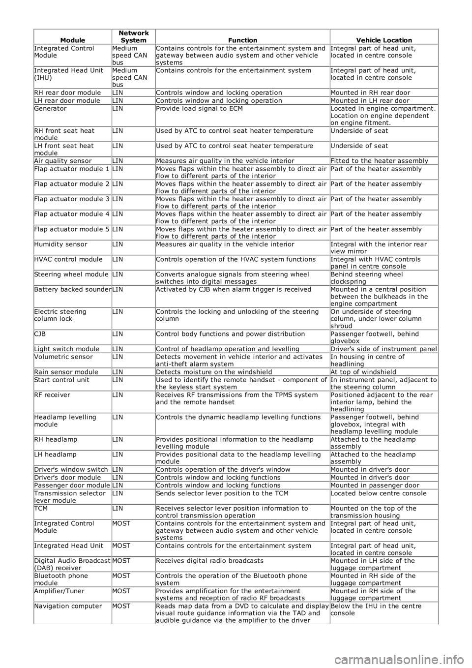
ModuleNetw orkSystemFunctionVehicle Location
Integrat ed Cont rolModuleMedi umspeed CANbus
Contains controls for the ent ert ai nment sys t em andgateway between audio s ys t em and ot her vehicles ys t ems
Int egral part of head uni t,located i n cent re cons ole
Integrat ed Head Unit(IHU)Medi umspeed CANbus
Contains controls for the ent ert ai nment sys t emInt egral part of head uni t,located i n cent re cons ole
RH rear door moduleLINControl s wi ndow and locki ng operati onMount ed i n RH rear door
LH rear door moduleLINControl s wi ndow and locki ng operati onMount ed i n LH rear doorGenerat orLINProvide l oad s ignal t o ECMLocat ed in engine compart ment .Locat ion on engine dependenton engine fit ment.
RH front s eat heatmoduleLINUs ed by ATC t o cont rol s eat heat er temperat ureUnders ide of s eat
LH front s eat heatmoduleLINUs ed by ATC t o cont rol s eat heat er temperat ureUnders ide of s eat
Air quali ty sens orLINMeasures air qualit y i n t he vehi cl e int eri orFit ted t o t he heater as sembl y
Flap act uat or modul e 1LINMoves fl aps wit hi n t he heat er ass embl y to direct airfl ow t o different parts of t he i nt eri orPart of t he heat er as s embly
Flap act uat or modul e 2LINMoves fl aps wit hi n t he heat er ass embl y to direct airfl ow t o different parts of t he i nt eri orPart of t he heat er as s embly
Flap act uat or modul e 3LINMoves fl aps wit hi n t he heat er ass embl y to direct airfl ow t o different parts of t he i nt eri orPart of t he heat er as s embly
Flap act uat or modul e 4LINMoves fl aps wit hi n t he heat er ass embl y to direct airfl ow t o different parts of t he i nt eri orPart of t he heat er as s embly
Flap act uat or modul e 5LINMoves fl aps wit hi n t he heat er ass embl y to direct airfl ow t o different parts of t he i nt eri orPart of t he heat er as s embly
Humi di ty sens orLINMeasures air qualit y i n t he vehi cl e int eri orInt egral wit h t he int eri or rearview mirror
HVAC control modul eLINControl s operat ion of t he HVAC s ys t em funct ionsInt egral wit h HVAC controlspanel i n cent re cons ole
St eering wheel moduleLINConverts analogue s ignals from s teering wheels wit ches i nto di git al mes s agesBehi nd s teering wheelclocks pri ngBatt ery backed s ounderLINActi vat ed by CJB when alarm t ri gger i s receivedMount ed i n a central pos it ionbetween t he bulkheads i n t heengi ne compartment
Electric st eeringcolumn l ockLINControl s t he locking and unlocki ng of the st eeri ngcol umnOn unders ide of s t eeringcol umn, under lower columns hroud
CJBLINControl body funct ions and power di st ributi onPass enger footwell , behi ndglovebox
Light s wit ch moduleLINControl of headlamp operat ion and l evel lingDri ver's s i de of ins trument panelVolumet ri c s ens orLINDetects movement i n vehicle i nterior and act ivatesanti -t heft alarm s ys temIn hous ing in centre ofheadl ining
Rain sens or modul eLINDetects mois t ure on t he wi nds hiel dAt top of windshi el dSt art cont rol unitLINUs ed to identi fy t he remote hands et - component oft he keyles s s t art s yst emIn ins trument panel, adjacent tothe st eeri ng col umnRF recei verLINRecei ves RF trans mi s si ons from t he TPMS s yst emand t he remot e hands etPosi ti oned adjacent t o the rearint erior l amp, behi nd theheadl ining
Headlamp l evel li ngmoduleLINControl s t he dynami c headl amp l evell ing funct ionsPass enger footwell , behi ndglovebox, int egral wit hheadl amp levell ing module
RH headlampLINProvides pos it ional i nformati on to the headlamplevell ing moduleAtt ached t o t he headl ampass embl y
LH headlampLINProvides pos it ional dat a t o t he headlamp levell ingmoduleAtt ached t o t he headl ampass embl y
Driver's window s wi tchLINControl s operat ion of t he driver's wi ndowMount ed i n dri ver's door
Driver's door moduleLINControl s wi ndow and locki ng functi onsMount ed i n dri ver's doorPas senger door moduleLINControl s wi ndow and locki ng functi onsMount ed i n pass enger door
Trans mi ss ion sel ect orl ever moduleLINSends sel ect or l ever pos it ion t o t he TCMLocat ed bel ow centre cons ole
TCMLINRecei ves s elect or l ever pos it ion i nformat ion tocont rol t rans mis s ion operat ionMount ed on t he t op of thetransmis s ion housi ngIntegrat ed Cont rolModuleMOSTContains controls for the ent ert ai nment sys t em andgateway between audio s ys t em and ot her vehicles ys t ems
Int egral part of head uni t,located i n cent re cons ole
Integrat ed Head UnitMOSTContains controls for the ent ert ai nment sys t emInt egral part of head uni t,located i n cent re cons oleDi gi tal Audio Broadcas t(DAB) recei verMOSTRecei ves di git al radi o broadcast sMount ed i n LH s ide of t heluggage compartmentBluet oot h phonemoduleMOSTControl s t he operati on of the Bl uet ooth phones ys t emMount ed i n RH s i de of theluggage compartment
Ampl ifi er/TunerMOSTProvides ampl ifi cat ion for the ent ert ainments ys t ems and recepti on of radio RF broadcas t sMount ed i n RH s i de of theluggage compartment
Navigati on comput erMOSTReads map data from a DVD t o cal cul ate and di spl ayvis ual route gui dance i nformat ion vi a t he TAD andaudi ble gui dance via the ampl ifier to the driver
Below t he IHU i n t he cent recons ole
Page 2313 of 3229
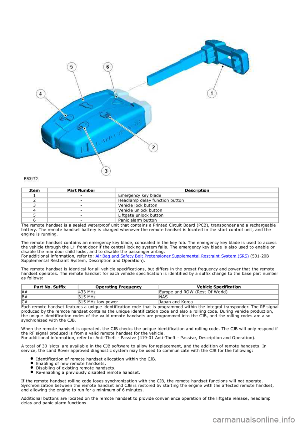
ItemPart NumberDescription1-Emergency key bl ade2-Headl amp delay funct ion but ton3-Vehicl e l ock button4-Vehicl e unlock button5-Li ftgate unlock butt on6-Panic alarm buttonThe remote hands et is a seal ed wat erproof uni t t hat contains a Printed Ci rcuit Board (PCB), transponder and a rechargeablebattery. The remote hands et batt ery i s charged whenever the remote hands et is located i n the s tart cont rol unit , and t heengi ne is running.
The remote hands et cont ai ns an emergency key blade, conceal ed in t he key fob. The emergency key bl ade i s us ed to acces sthe vehicle through the LH front door i f t he central locki ng syst em fai ls. The emergency key bl ade is als o us ed t o enable ordis able t he rear door chil d locks , and t o dis able t he pas senger ai rbag.For addit ional informat ion, refer t o: Ai r Bag and Safet y Belt Pretens ioner Supplement al Rest raint Sys tem (SRS) (501-20BSupplemental Res traint Sys tem, Des cription and Operat ion).
The remote hands et is identi cal for all vehicl e s peci ficat ions, but di ffers in t he pres et frequency and power that the remotehandset operates. The remot e handset for each vehicle specificat ion is ident ifi ed by a s uffix change to the base part numberas follows:
Part No. SuffixOperating FrequencyVehicle SpecificationA#433 MHzEurope and ROW (Rest Of W orld)B#315 MHzNASC#315 MHz low powerJapan and KoreaEach remot e handset features a uni que ident ifi cation code that is programmed within t he integral trans ponder. The RF si gnalproduced by t he remot e handset contains t he uni que ident ifi cation code and also a rolli ng code. Duri ng vehicl e product ion,the unique identification codes of the valid remot e handsets are programmed int o the CJB, and the roll ing codes are al sosynchronized wi th the CJB.
W hen the remote handset is operat ed, t he CJB checks t he unique i dent ificat ion and rol ling code. The CJB will only respond ifthe RF si gnal produced is from a val id remote hands et for the vehicle.For addit ional informat ion, refer t o: Anti -Theft - Pas si ve (419-01 Anti -Theft - Pas si ve, Des cript ion and Operati on).
A tot al of 30 'sl ots ' are availabl e in the CJB s oftware to al low for repl acement, and the addi tion of remote hands et s. Inservi ce, t he Land Rover approved di agnost ic system may be us ed to communicat e wit h the CJB for the followi ng:
Identi ficati on of remote handset all ocat ion wit hin t he CJB.Enabli ng of new remot e handsets .Disabl ing of exist ing remote handsets .Re-enabling a previ ously disabled remot e handset.
If the remote hands et rolling code l os es synchronizati on with t he CJB, t he remot e handset funct ions will not operate.Synchronizati on between the remote hands et and CJB is rest ored by s tart ing t he engine wit h t he affect ed remot e handset,and all owing the engine to run for a minimum of 6 mi nutes.
Addi tional buttons are located on the remote hands et to provide convenience operati on of t he li ftgat e rel ease, headlampdelay and panic al arm functions .
Page 2346 of 3229
Fli ck wipeInt ermit tent/Auto (vehicles wi thout/wit h rain s ens or fit t ed)Slow wipeFast wi pe.
The 'Aut o' funct ion requi res an i nput from t he rai n s ens or. The rain s ens or i s mounted on the inner s urface of thewinds hield and trans mi ts an infra-red s ignal to det ermine t he amount of wat er on the out er surface of t he winds hi eld. Avalue i s then t rans mi tt ed to the CJB over the Local Int erconnect Network (LIN) bus .
The CJB als o control s operat ion of t he headlamp was h functi on. For more informat ion, refer t o 'Headl amp W as hers ' bel ow.
The rear s creen wi per s yst em operat es i ndependent ly of t he winds hield wiper s ys t em and i s cont rol led by t he CJB onreceipt of LIN bus mes sages from the RH s teeri ng col umn mul ti -funct ion s wi tch.
• NOTE: The wi nds hield and rear s creen was hers uti li ze the s ame pump meaning only 1 was h functi on, ei ther front or rear,can be performed at any one t ime.
WINDSHIELD WIPER MOTOR
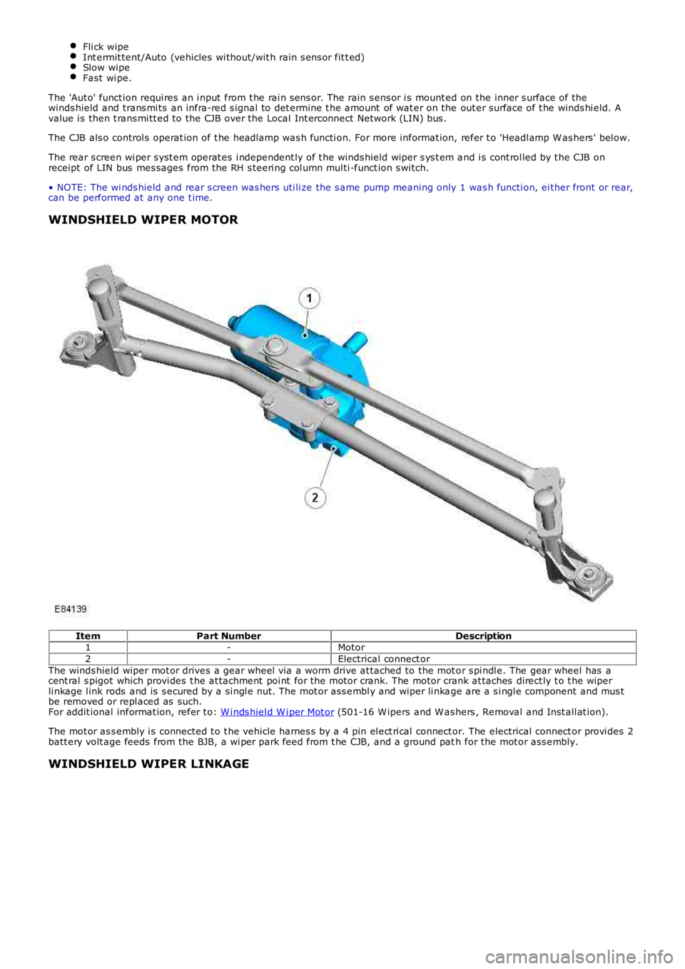
ItemPart NumberDescription1-Motor
2-Electrical connect or
The winds hield wiper mot or drives a gear wheel via a worm drive at tached to the mot or s pi ndl e. The gear wheel has acent ral s pigot which provi des t he at tachment poi nt for the motor crank. The motor crank at taches direct ly t o t he wiperli nkage l ink rods and is s ecured by a si ngl e nut. The mot or ass embl y and wiper li nkage are a s i ngl e component and mus tbe removed or repl aced as such.For addit ional informat ion, refer t o: W i nds hiel d W i per Mot or (501-16 W ipers and W as hers , Removal and Inst all at ion).
The mot or as s embly i s connected t o t he vehicle harnes s by a 4 pin el ect ri cal connector. The electrical connect or provi des 2batt ery volt age feeds from the BJB, a wi per park feed from t he CJB, and a ground path for the mot or ass embly.
WINDSHIELD WIPER LINKAGE
Page 2352 of 3229
t o the 'Owners Handbook'.
Rear Screen Wiper
On recei vi ng a reques t for rear s creen wi per operat ion the CJB wi ll energize relay RA2 i n t he AJB. W hen energized, relayRA2 provides a feed t o t he rear s creen wiper mot or. The rear s creen wi per operat es int ermi tt entl y, wi th a delay betweenwipes of approximat ely 6 seconds . The CJB cont rol s operati on of rel ay RA2, and consequentl y rear s creen wiper mot oroperati on, accordingly.
The CJB als o provi des a feed t o t he rear s creen wi per mot or park s wit ch. The park s wit ch is i ntegral wi th the rear s creenwiper mot or and ens ures t he wi per returns to the park pos i ti on if t he rear wi per reques t is cancel led mid-st roke. The parks wit ch cont act s are cl osed when the rear wiper is i n any posi ti on except t he park pos it ion. Thi s all ows the CJB to returnt he rear wiper t o t he park pos it ion when relay RA2 i s de-energized.
The CJB wil l als o power the rear screen wiper motor i f revers e gear is s elected whi le the wi nds hiel d wi per funct ion i sact ive. On vehicles fit t ed wit h an aut omat ic trans mi s si on, t he reverse gear s ignal origi nat es in the Transmis si on ControlModule (TCM). The TCM broadcas ts a revers e gear s ignal over the hi gh s peed CAN bus to the CJB, which responds byoperati ng t he rear wiper.
On vehicles fit ted wit h a manual transmis s ion, the revers e gear s i gnal ori ginates at t he revers e gear s wit ch. The reversegear s wi tch i s hardwired t o t he CJB.
Windshield Washers
On recei vi ng a reques t for wi nds hiel d was her operat ion t he CJB wi ll energize t he front washer cont rol relay. Thi s all ows abatt ery volt age feed t o flow to the was her pump. A ground path for t he pump is provided by t he de-energized rear was hercont rol rel ay. Bot h was her control relays are int egral wit h t he CJB.
W hen wi ndshi el d was her operat ion i s reques ted, t he winds hi eld was hers will operat e. The CJB will delay wiper operati onfor 100 ms aft er the was her swi tch i s pres s ed. If t he s wit ch is pres s ed for l ess than 100 ms, t he CJB wil l not operat e t hewipers.
The CJB wil l power t he wi nds hield wipers for as l ong as washer operati on is reques t ed, al though t he washers wil l ti me outaft er 10 s econds. After t he was her s wi tch has been rel eas ed, the CJB wi ll operat e t he winds hi eld wipers t hrough 2 morewipe cycles .
Rear Screen Washer
On recei vi ng a reques t for rear s creen was her operati on the CJB wi ll energize the rear was her cont rol rel ay. This al lows abatt ery volt age feed t o flow to the was her pump. A ground path for t he pump is provided by t he de-energized front was hercont rol rel ay. Revers ing the polarit y of the pump (s ee 'W i nds hield W as hers ' above) allows was her fl uid t o be di rected t ot he rear s creen washer jet rather t han the windshi el d was her jets . The rear s creen was her jet is incorporat ed int o the hi ghmounted s t op lamp.
The rear s creen was her wi ll operat e for up t o 10 seconds if cont inuousl y reques ted. W hen rear s creen was her operati on isreques ted, the rear screen wiper wil l operat e conti nuous ly unt il t he s wit ch is released. After t he swit ch has been released,or fol lowing 10 seconds of conti nuous operat ion, the CJB will operat e t he rear s creen wiper t hrough 2 or 3 more wi pecycles .
Headlamp Washers
W hen t he vehicle ent ers i gni ti on mode 4 (acces s ory) to 7 (engine running) the firs t winds hield was h reques t great er than100 ms will operat e a headlamp power was h s equence. The CJB will t hen s tart a 10 mi nut e t imer. If 5 request s forwinds hield washer operati on are made wit hin this 10 mi nut e wi ndow, t he CJB wil l power t he headl amp was hers uponreceiving the fifth reques t . W hen t his occurs , the 10 minute ti mer is res et t o 0.
If the CJB receives no windshi el d was her reques t s duri ng a 10 mi nute window, the headlamp was hers will operat e on t hefi rs t reques t received aft er the 10 minut e window has el aps ed. Agai n, once t he headlamp was hers have been operati onal ,t he CJB res ets t he t imer t o 0.
The headl amp was hers wi ll only operat e when t he headl amps are on. The CJB receives a 'li ght s on' si gnal from the lightcont rol module over t he LIN bus .
W hen headlamp was her operati on is required, t he CJB energizes rel ay 9 in the BJB, all owing a bat tery vol tage feed t opower the headlamp was her pump. A ground path for t he washer pump i s provided by t he de-energi zed relay 12, which i sals o l ocat ed in the BJB. Thi s s equence of event s provides was her flui d t o the headlamp 1 was her jets .
Aft er thi s s equence the power s uppl y t o t he pump is revers ed. The CJB does t his by de-energi zing rel ay 9 and energi zi ngrel ay 12. Thi s allows the pump to provi de was her flui d to the headlamp 2 was her jets. The s equence of event s runs asfol lows :
Power to headlamp 1 was her - 500 msDelay t o power headl amp 2 was her - 100 msPower to headlamp 2 was her - 500 msDelay (s oak ti me) to power 1 headlamp washer - 700 msPower to 1 headl amp was her - 500 msDelay t o power 2 headl amp was her - 100 msPower to 2 headl amp was her - 500 ms
If there is l ess than 1 l it er (0.26 US gall on) of was her flui d in the was her fl uid reservoi r, t he CJB wil l s us pend headl ampwas her operat ion. The fl uid l evel s wit ch is hardwired to the CJB, which als o t rans mits a low fl ui d s ignal to the i nst rumentclus ter over t he medi um s peed CAN bus. For addit ional i nformati on, refer to:
Ins trument Clus ter (413-01 Ins t rument Clus t er, Descripti on and Operat ion),Informat ion and Mes s age Cent er (413-08 Informati on and Mes sage Cent er, Descripti on and Operat ion).
Page 2353 of 3229
Publi s hed: 11-May-2011
Wipers and Washers - Wipers and Washers
Diagnosi s and Tes ti ng
Principles of Operation
For a detail ed descripti on of the wiper and washer s yst ems , refer t o t he rel evant De s cript ion and Operat ion secti on in the
works hop manual .
REFER to: W ipers and W ashers (501-16 W i pers and W as hers , Descripti on and Operat ion).
Inspection and Verification CAUTION: Di agnos is by s ubs ti tut ion from a donor vehicle is
NO T acceptabl e. Subs ti tut ion of cont rol modules does
not guarant ee confirmat ion of a faul t, and may als o caus e addit ional fault s i n t he v ehi cl e being t est ed and/or t he donor
vehi cl e.
1. Verify t he cus t omer concern.
1.
2. Vis ually ins pect for obvious s igns of mechani cal or electrical damage.
2.
Visual Inspection Mechanical Electrical
W iper bl ades W iper pi vot arm shaft
W as her res ervoir
Hos e(s )
W as her jet (s ) Fus es /rel ays (refer t o electrical gui de)
W iring harnes s
Correct engagement of electrical connect ors
Loos e or corroded connect ions
3.
If an obvious cause for an obs erved or report ed concern is found, correct t he caus e (if pos s ible) before
proceeding t o t he next s t ep.
3.
4. If t he caus e is not vis ually evi dent , check for Di agnos ti c Trouble Codes (DTCs) and refer t o t he DTC Index.
4.
DTC Index
• NOTE: If the control modul e or a component i s s us pect and the vehicle remains unde r manufacturer warrant y, refer t o the
W arranty Pol icy and Procedures manual (s ect ion B1.2), or determine i f any pri or appr oval programme is in operat ion, pri or
t o the ins tall ati on of a new module/component.
• NOTE: Generic scan t ool s may not read the codes li st ed, or may read only fi ve digi t codes . Mat ch the five di git s from t he
s can tool to the firs t fi ve di git s of the seven digi t code l is ted to ident ify t he fa ul t (t he las t t wo digi ts gi ve ext ra
informat ion read by the manufact urer-approved diagnost ic s ys tem).
• NOTE: W hen performing volt age or res is t ance t est s , always use a digi tal mult imeter (DMM) accurat e t o t hree deci mal
places and wit h a current cal ibrat ion cert ificate. W hen tes ti ng res i st ance, always t ake the res is tance of the DMM l eads i nto
account.
• NOTE: Check and recti fy bas ic faul ts before beginni ng diagnos t ic rout ines i nvol vi n g pinpoint t es t s.
• NOTE: If DTCs are recorded and, aft er performi ng the pi npoi nt tes ts , a fault is no t present , an int ermi tt ent concern may
be t he caus e. Always check for loose connect ions and corroded terminals .
DT C Description Possible Cause Action
B109512 W iper On/O ff Relay - circui t
s hort t o power W i per On/Off relay ci rcuit -
s hort t o power Refer to el ect ri cal circui t diagrams and
check wiper On/O ff rel ay circuit for s hort to
power
B109514 W iper On/O ff Relay - circui t
s hort t o ground or open W i per On/Off relay ci rcuit -
s hort t o ground, open ci rcuit Refer to el ect ri cal circui t diagrams and
check wiper On/O ff rel ay circuit for s hort to
ground, open circui t
B109612 W iper High/Low Relay - circui t
s hort t o power W i per High/Low relay circui t -
s hort t o power Refer to el ect ri cal circui t diagrams and
check wiper High/Low rel ay ci rcuit for short
to power
B109614 W iper High/Low Relay - circui t
s hort t o ground or open W i per High/Low relay circui t -
s hort t o ground, open ci rcuit Refer to el ect ri cal circui t diagrams and
check wiper High/Low rel ay ci rcuit for short
to ground, open circuit
B10AD04 Rai n Sens or - Syst em Int ernal
Fail ure Int ernal s ens or fai lure Ins tal l a new rai n s ensor.
REFER t o: Rain Sens or (501-16 W ipers and
W as hers, Removal and Ins t al lat ion).
B10AD09 Rai n Sens or - Component
Fail ures Rain sens or incorrectl y
ins t al led Rain sens or internal failure Check for correct i nst all ati on of rain
sens or. Ins t all a new sens or as required.
REFER t o: Rain Sens or (501-16 W ipers and
W as hers, Removal and Ins t al lat ion).
B113188 W iper Motor Module - Bus off Lost communi cat ions wit h
wi per mot or modul e Carry out di agnos ti c s trat egy as sociat ed
wit h t hi s DTC us ing manufact urer approved
di agnos ti c s yst em
B1C8212 Headlamp W as her Rel ay Coi l
Ci rcuit - circui t s hort t o power Headlamp was her relay control
circui t - short to power Refer to el ect ri cal circui t diagrams and
check headl amp was her relay cont rol circui t
for s hort to power